MITSUBISHI SPYDER 1990 Service Repair Manual
SPYDER 1990
MITSUBISHI
MITSUBISHI
https://www.carmanualsonline.info/img/19/57345/w960_57345-0.png
MITSUBISHI SPYDER 1990 Service Repair Manual
Trending: glove box, checking oil, set clock, open hood, oil temperature, power steering, coolant level
Page 1241 of 2103
A U T O M A T I C T R A N S A X L E
OVERHAUL Transaxle
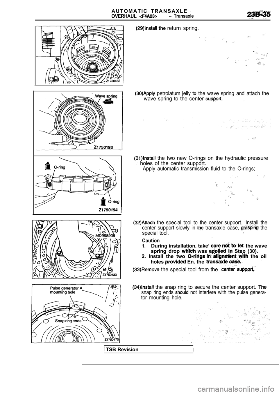
the return spring.
--
petrolatum jelly the wave spring and attach the
wave spring to the center ,
the two new O-rings on the hydraulic pressure
holes of the center suppdrt.
Apply automatic transmission fluid to the O-rings;
the special tool to the center support. ‘Install the
center support slowly in
transaxle case, the
special tool.
Caution
1.During installation, take’ the wave
spring drop
was Step (30).
2. Install the two
the oil
holes
En. the
the special tool from the
the snap ring to secure the center support.
snap ring ends not interfere with the pulse genera-
tor mounting hole.
TSB Revision.I
Page 1242 of 2103
AUTOMATIC TRANSAXLE
OVERHAUL Transaxle
D-ringO-ring
servo pistonservo
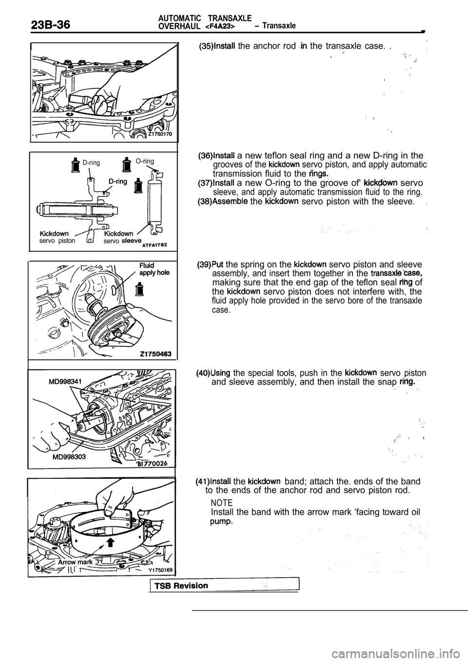
the anchor rod the transaxle case. .
.
a new teflon seal ring and a new D-ring in the
grooves of the servo piston, and apply automatic
transmission fluid to the
a new O-ring to the groove of‘ servo
sleeve, and apply automatic transmission fluid to the ring.
the servo piston with the sleeve.,
the spring on the servo piston and sleeve
assembly, and insert them together in the
making sure that the end gap of the teflon seal of
the
servo piston does not interfere with, the
fluid apply hole provided in the servo bore of the transaxle
case.
the special tools, push in the servo piston
and sleeve assembly, and then install the snap
,
,
the band; attach the. ends of the band
to the ends of the anchor rod and servo piston rod.
NOTE
Install the band with the arrow mark ‘facing toward oil
Page 1243 of 2103
AUTOMATIC
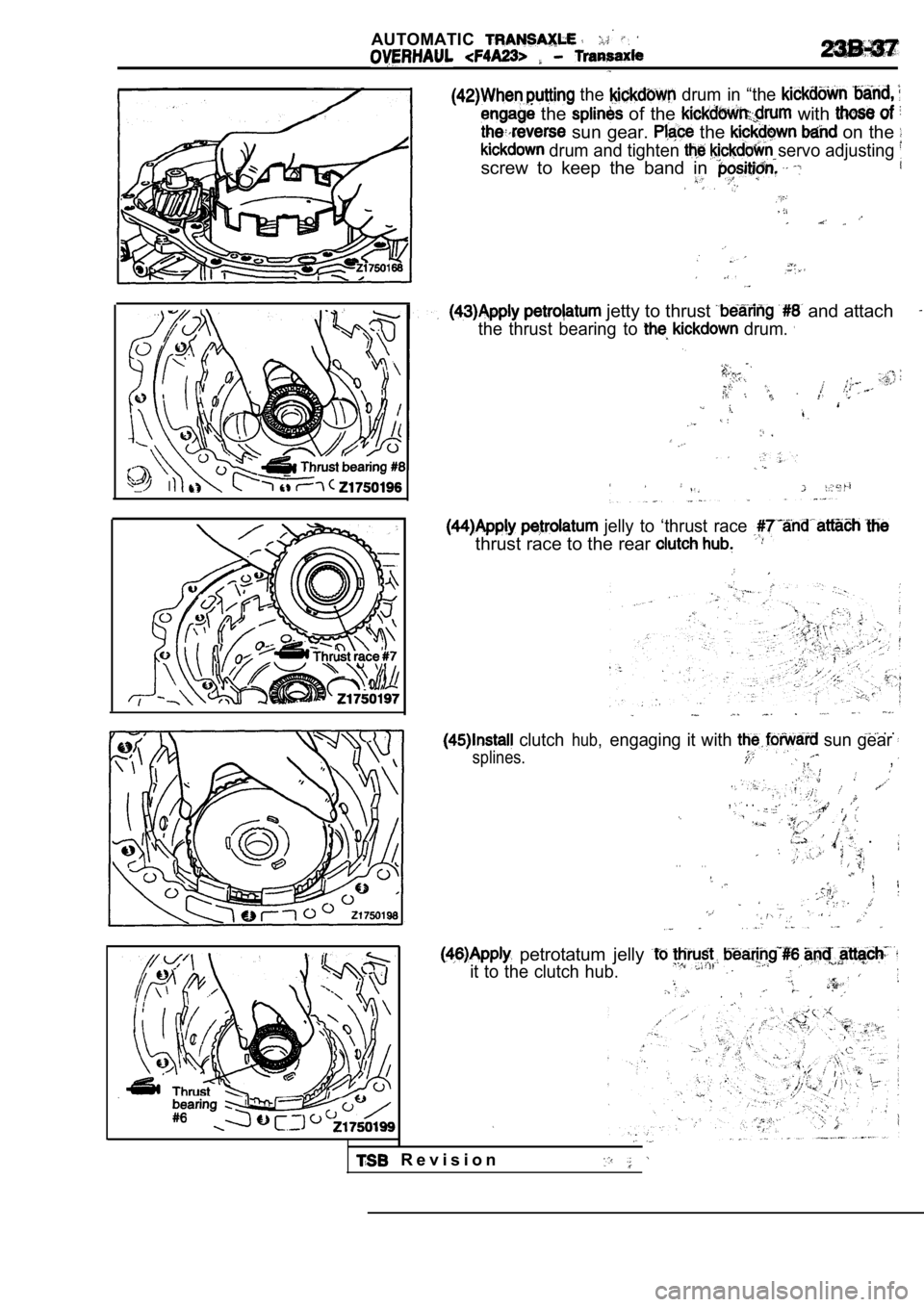
the drum in “the
the of the with
sun gear. the on the
drum and tighten servo adjusting
screw to keep the band in
jetty to thrust and attach
the thrust bearing to drum.
jelly to ‘thrust race
thrust race to the rear
clutch
splines.hub,
. .engaging it with sun gear
,
, . .
, .
. .. .
petrotatum jelly
it to the clutch hub.
R e v i s i o n
Page 1244 of 2103
RearFront clutch 21750201
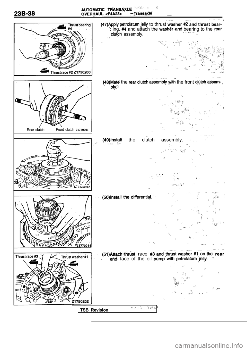
to thrust washer and thrust bear-
‘: ing. and attach the bearing to the
assembly.
.
. .
the the front ,
. ,
. .
the clutch assembly. .
.
,
. . , . .
.
. .
. . . .
race rear
face of the oil .
,
,. .
TSB Revision
Page 1245 of 2103
A U T O M A T I C
O V E R H A U L
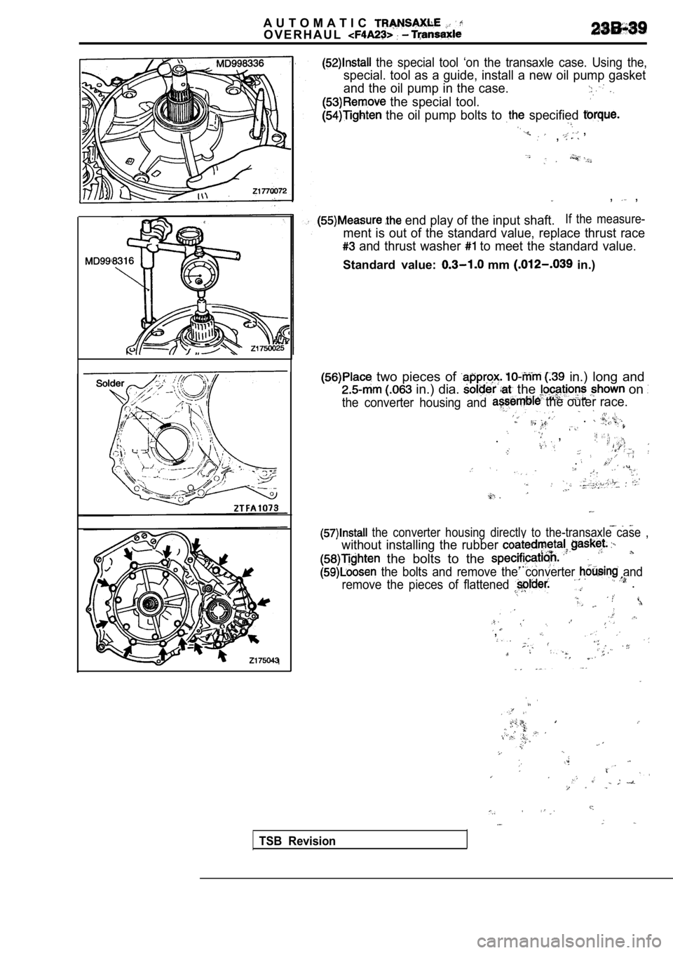
the special tool ‘on the transaxle case. Using the,
special. tool as a guide, install a new oil pump gasket
and the oil pump in the case.
the special tool.
the oil pump bolts to specified
,
,
, ,
1
end play of the input shaft.If the measure-
ment is out of the standard value, replace thrust r ace
and thrust washer to meet the standard value.
Standard value: mm in.)
two pieces of in.) long and
in.) dia. the on
the converter housing and the outer race.
.
,.
.
the converter housing directly to the-transaxle ca se ,
without installing the rubber
the bolts to the
the bolts and remove the’ converter and
remove the pieces of flattened
.
,
TSB Revision
Page 1246 of 2103
AUTOMATIC TRANSAXLE
OVERHAUL. .
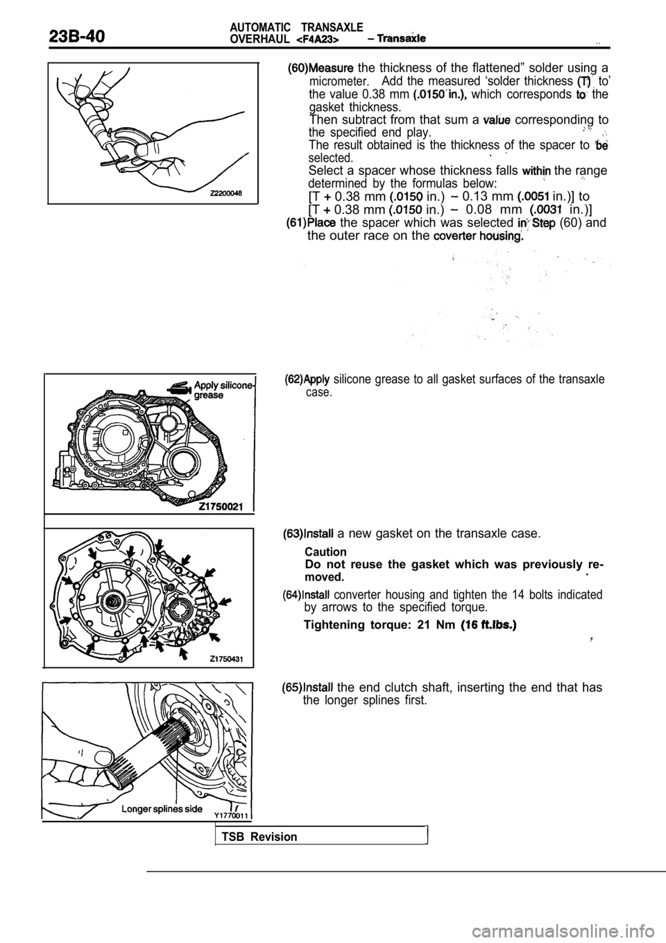
the thickness of the flattened” solder using a
micrometer.Add the measured ‘solder thickness to’
the value 0.38 mm
which corresponds the
gasket thickness.
Then subtract from that sum a corresponding to
the specified end play.
The result obtained is the thickness of the spacer to
selected..
Select a spacer whose thickness falls the range
determined by the formulas below:
[T 0.38 mm in.) 0.13 mm in.)] to
[T
0.38 mm in.) 0.08 mm in.)]
the spacer which was selected (60) and
the outer race on the
silicone grease to all gasket surfaces of the tran saxle
case.
a new gasket on the transaxle case.
Caution
Do not reuse the gasket which was previously re-
moved..
converter housing and tighten the 14 bolts indicat ed
by arrows to the specified torque.
Tightening torque: 21 Nm
the end clutch shaft, inserting the end that has
the longer splines first.
TSB Revision
Page 1247 of 2103
AUTOMATIC TRANSAXLE
OVERHAUL Transaxle
Thrust bearing .
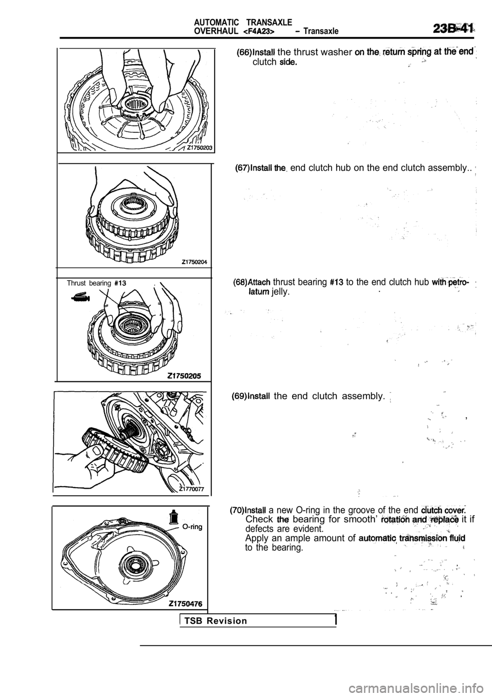
the thrust washer
clutch
end clutch hub on the end clutch assembly..
thrust bearing to the end clutch hub
jelly..
the end clutch assembly.
,
a new O-ring in the groove of the end
Check bearing for smooth’ it if
defects are evident.
Apply an ample amount of
to the bearing.
,
. .. ,
TSB R e v i s i o n1
Page 1248 of 2103
AUTOMATIC TRANSAXLE
OVERHAUL . .
Manual control
shaft
O-ring
groove
Set screw
,
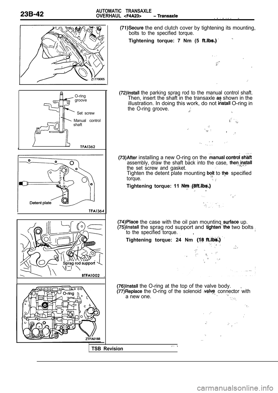
the end clutch cover by tightening its mounting,
bolts to the specified torque.
Tightening torque: 7 Nm (5
the parking sprag rod to the manual control shaft.
Then, insert the shaft in the transaxle shown in the
illustration. In doing this work, do not O-ring in
the O-ring groove.
,
installing a new O-ring on the
assembly, draw the shaft back into the case,
the set screw and gasket.
Tighten the detent plate mounting to specified
torque.
Tightening torque: 11 .
the case with the oil pan mounting up.
the sprag rod support and two bolts
to the specified torque. ,
Tightening torque: 24 Nm
. .
the O-ring at the top of the valve body..
the O-ring of the solenoid connector with
a new one.
. .
TSB Revision
Page 1249 of 2103
,
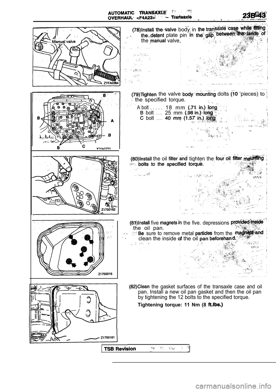
body in
plate pin
the valve,
the valve dolts ‘pieces) to
the specified torque.
A bolt . . . . .
.
bolt
1 8 m m
. . . . .
bolt
25 mm
. . . . .
__ ,
. .
the oil tighten the
five the five. depressions
, . .
the oil pan.
sure to remove metal from the .clean the inside the oil pan
the gasket surfaces of the transaxle case and oil
pan. Install a new oil pan gasket and then the oil pan
by tightening the 12 bolts to the specified torque.
Tightening torque: 11 Nm (8
Page 1250 of 2103
AUTOMATIC TRANSAXLE
OVERHAUL
I
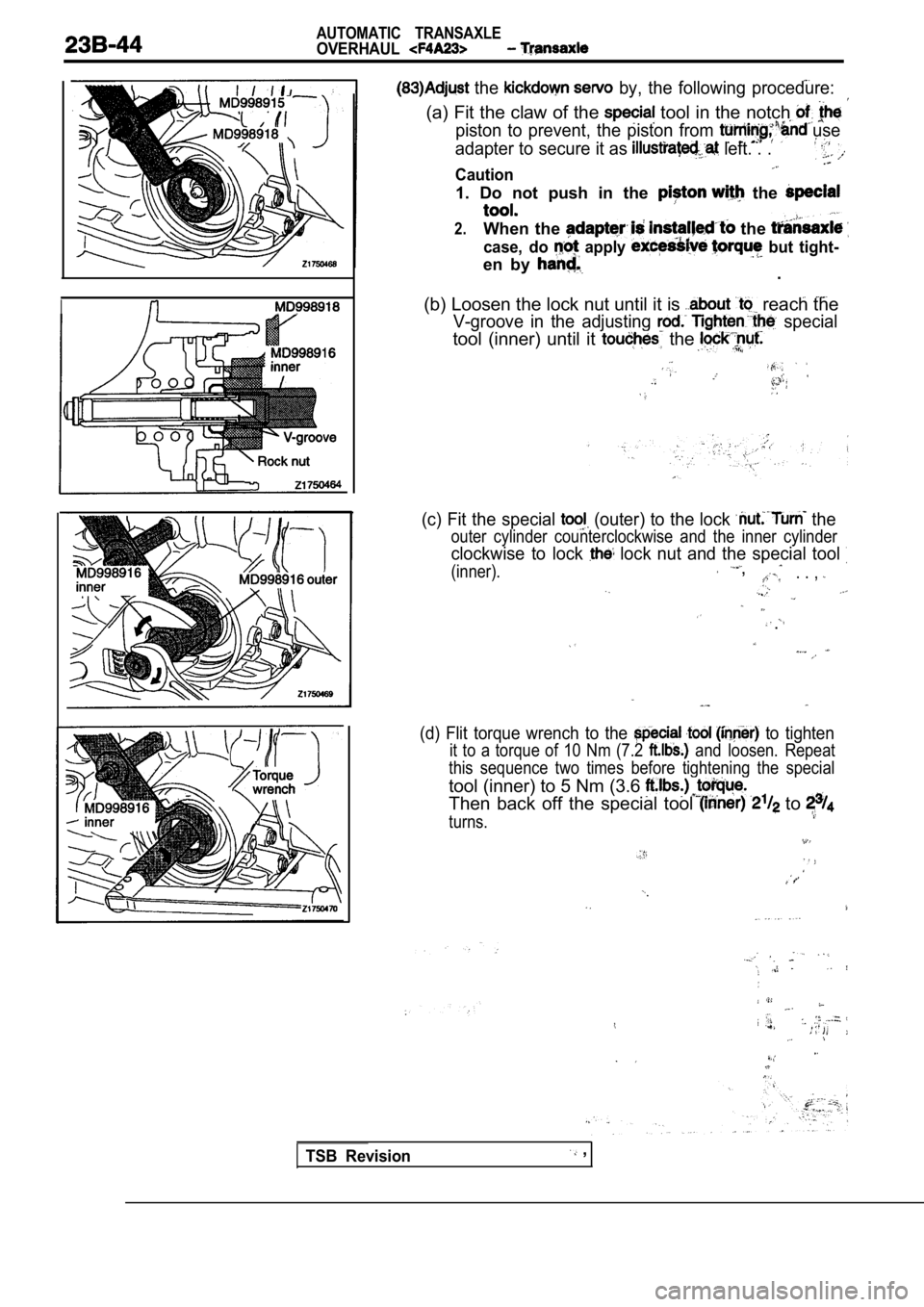
the by, the following procedure:
(a) Fit the claw of the tool in the notch
piston to prevent, the piston from use
adapter to secure it as
left. . .
Caution
1. Do not push in the the
2.When the the
case, do apply but tight-
en by .
(b) Loosen the lock nut until it is reach the
V-groove in the adjusting special
tool (inner) until it the
(c) Fit the special (outer) to the lock the
outer cylinder counterclockwise and the inner cylin der
clockwise to lock lock nut and the special tool
(inner). ,. . ,
.
(d) Flit torque wrench to the to tighten
it to a torque of 10 Nm (7.2 and loosen. Repeat
this sequence two times before tightening the speci al
tool (inner) to 5 Nm (3.6
Then back off the special tool to
turns.
TSB Revision ,
Trending: wiper fluid, spark plugs, oil filter, hood release, roof rack, tire size, change wheel
