MITSUBISHI SPYDER 1990 Service Repair Manual
SPYDER 1990
MITSUBISHI
MITSUBISHI
https://www.carmanualsonline.info/img/19/57345/w960_57345-0.png
MITSUBISHI SPYDER 1990 Service Repair Manual
Trending: child lock, set clock, fuel filter, air bleeding, wiring, catalytic converter, compression ratio
Page 1271 of 2103
Lock pin
AUTOMATIC TRANSAXLE
OVERHAUL Differential
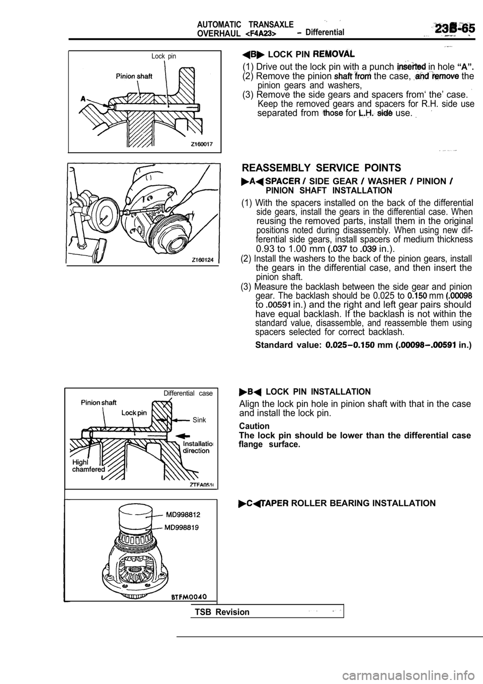
LOCK PIN
(1) Drive out the lock pin with a punch in hole “A”.
(2) Remove the pinion the case, the
pinion gears and washers,
(3) Remove the side gears and spacers from‘ the’ case.
Keep the removed gears and spacers for R.H. side us e
separated from for use.
REASSEMBLY SERVICE POINTS
SIDE GEAR WASHER PINION
PINION SHAFT INSTALLATION
(1) With the spacers installed on the back of the differential
side gears, install the gears in the differential case. When
reusing the removed parts, install them in the orig inal
positions noted during disassembly. When using new dif-
ferential side gears, install spacers of medium thickness
0.93 to 1.00 mm to in.).
(2) Install the washers to the back of the pinion gears, install
the gears in the differential case, and then insert the
pinion shaft.
(3) Measure the backlash between the side gear and pinion
gear. The backlash should be 0.025 to
mm
to in.) and the right and left gear pairs should
have equal backlash. If the backlash is not within the
standard value, disassemble, and reassemble them us ing
spacers selected for correct backlash.
Standard value: mm in.)
Differential case
Sink
I
LOCK PIN INSTALLATION
Align the lock pin hole in pinion shaft with that i n the case
and install the lock pin.
Caution
The lock pin should be lower than the differential case
flange surface.
ROLLER BEARING INSTALLATION
TSB Revision
Page 1272 of 2103
AUTOMATIC TRANSAXLE
OVERHAUL
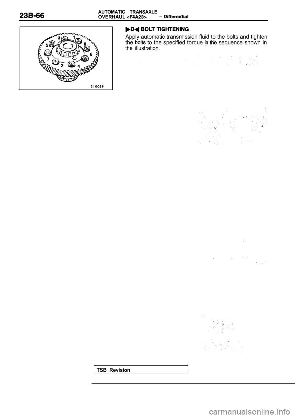
Apply automatic transmission fluid to the bolts and tighten
the
to the specified torque sequence shown in
the illustration.
TSB Revision
Page 1273 of 2103
AUTOMATIC TRANSAXLE
OVERHAUL Brake
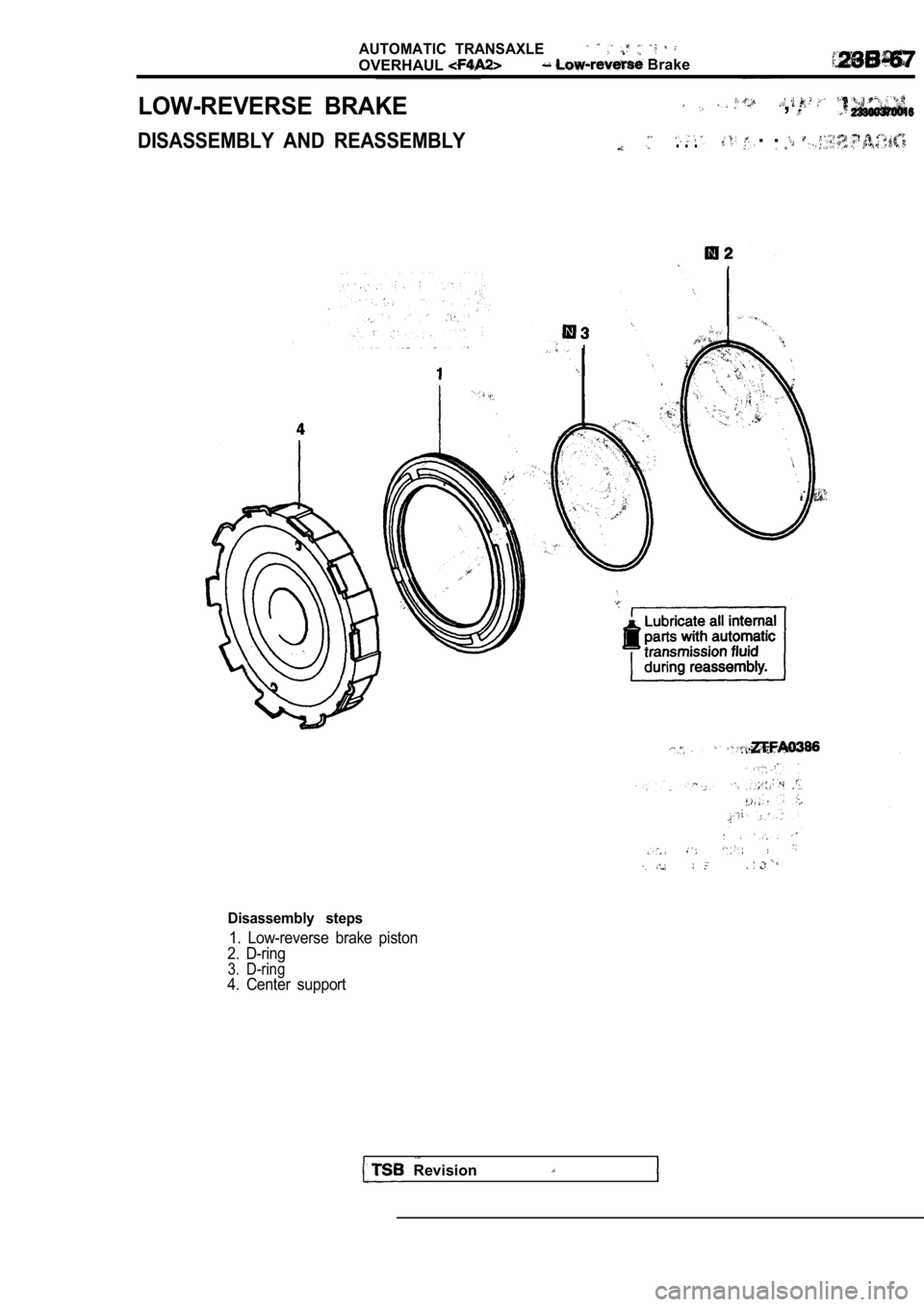
LOW-REVERSE BRAKE,
DISASSEMBLY AND REASSEMBLY. . . . .
Disassembly steps
1. Low-reverse brake piston
2. D-ring
3. D-ring4. Center support
Revision
Page 1274 of 2103
AUTOMATIC TRANSAXLE
OVERHAUL Servo
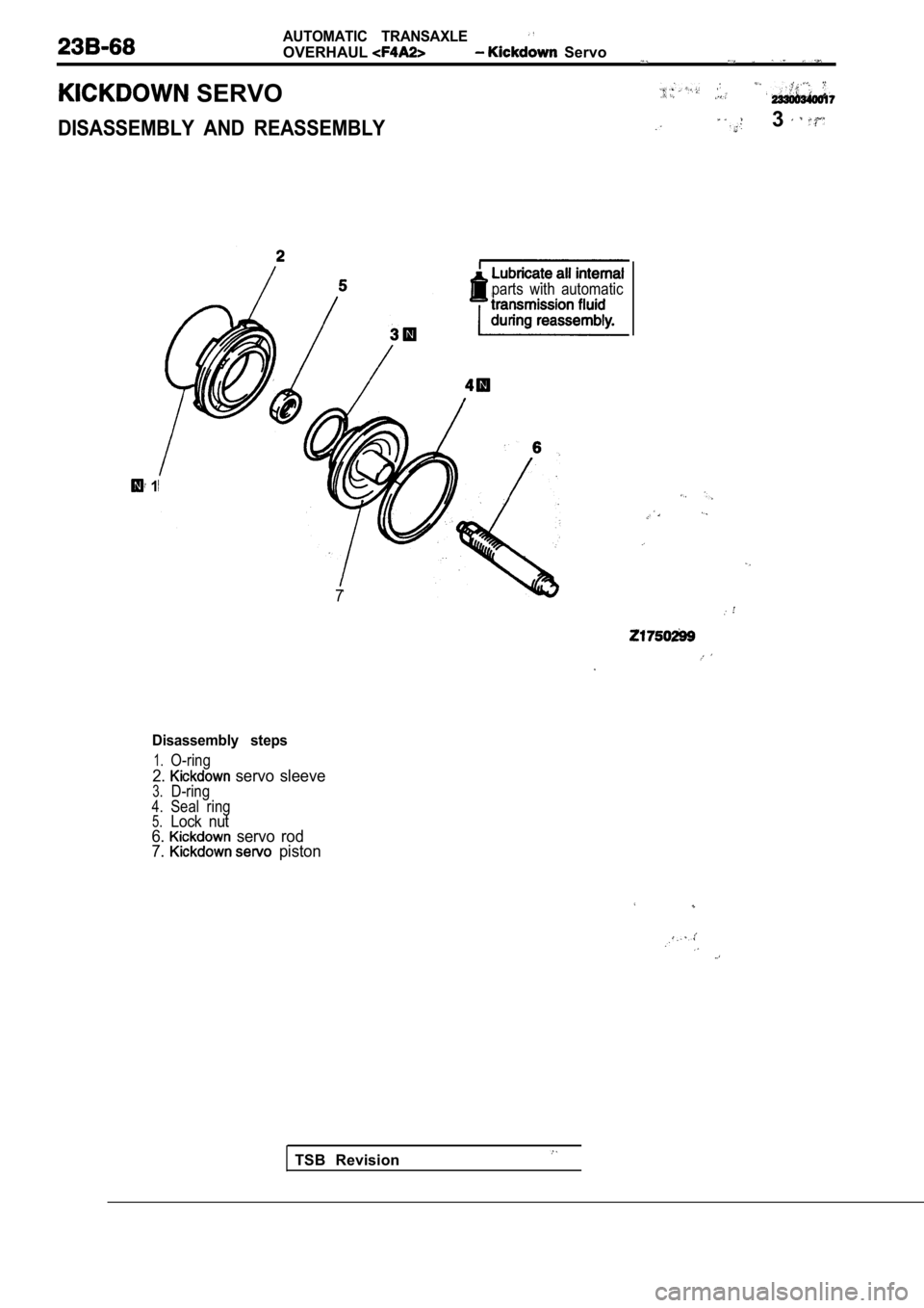
SERVO
DISASSEMBLY AND REASSEMBLY3
parts with automatic
1
7
TSB Revision
Disassembly steps
1.O-ring
2. servo sleeve3.D-ring4.Seal ring5.Lock nut6. servo rod
7. piston
Page 1275 of 2103
A U T O M A T I C T R A N S A X L E ’
OVERHAUL Gear
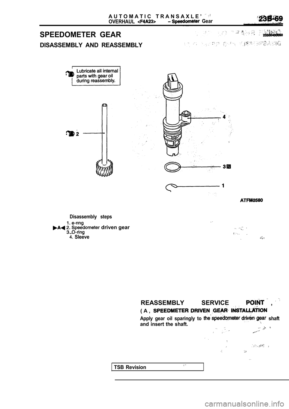
SPEEDOMETER GEAR
DISASSEMBLY AND REASSEMBLY
Disassembly steps
driven gear
Sleeve
REASSEMBLY SERVICE ,
( A ,
Apply gear oil sparingly to shaft
and insert the shaft.
TSB Revision
Page 1276 of 2103
AUTOMATIC TRANSAXLE
OVERHAUL-Drive Shaft
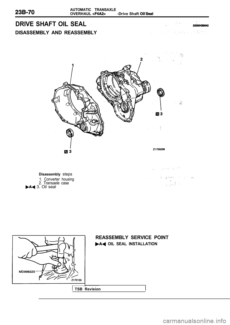
DRIVE SHAFT OIL SEAL
DISASSEMBLY AND REASSEMBLY
Disassemblysteps
1. Converter housing2. Transaxle case 3. Oil seal
REASSEMBLY SERVICE POINT
OIL SEAL INSTALLATION
TSB Revision
Page 1277 of 2103
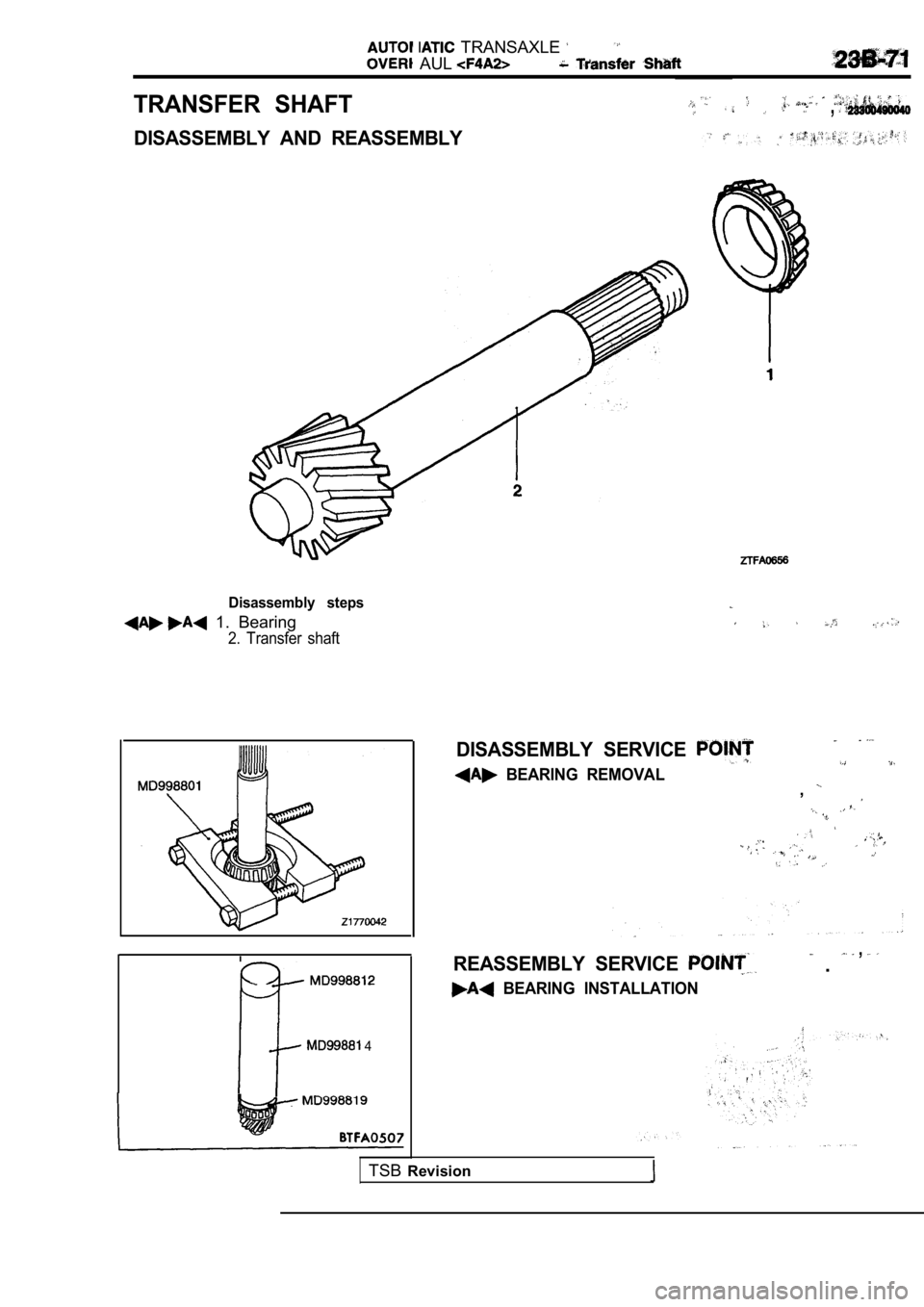
TRANSAXLE
AUL
TRANSFER SHAFT,
DISASSEMBLY AND REASSEMBLY
Disassembly steps
1. Bearing
2. Transfer shaft
4
DISASSEMBLY SERVICE
BEARING REMOVAL,
REASSEMBLY SERVICE .
,
BEARING INSTALLATION
TSBRevision
Page 1278 of 2103
AUTOMATIC TRANSAXLE
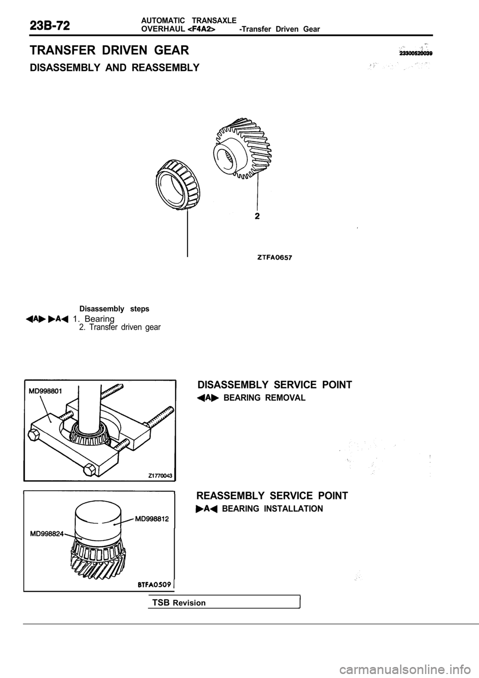
OVERHAUL-Transfer Driven Gear
TRANSFER DRIVEN GEAR
DISASSEMBLY AND REASSEMBLY
Disassembly steps
1. Bearing
2. Transfer driven gear
DISASSEMBLY SERVICE POINT
BEARING REMOVAL
REASSEMBLY SERVICE POINT
BEARING INSTALLATION
TSBRevision
Page 1279 of 2103
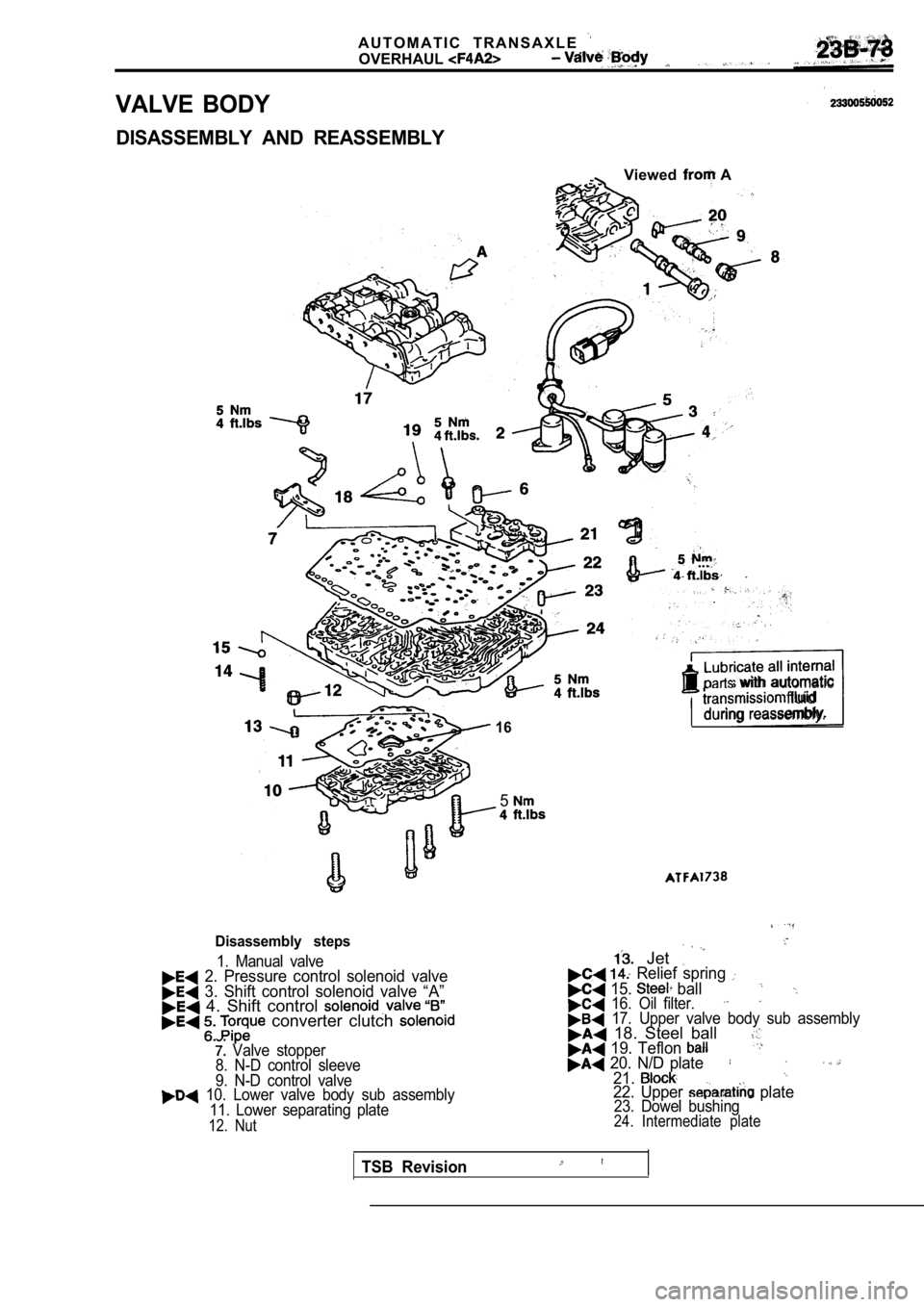
VALVE BODY
A U T O M A T I C T R A N S A X L E
OVERHAUL
DISASSEMBLY AND REASSEMBLY
Viewed A
. .
16
Lubricate all internal with automatic
fluid
during reassembly.
5
Disassembly steps
1. Manual valve 2. Pressure control solenoid valve 3. Shift control solenoid valve “A” 4. Shift control converter clutch
Valve stopper
8. N-D control sleeve
9. N-D control valve
10. Lower valve body sub assembly
11. Lower separating plate
12. Nut
Jet Relief spring
15. ball 16. Oil filter. 17. Upper valve body sub assembly 18. Steel ball 19. Teflon 20. N/D plate21.
22. Upper plate23. Dowel bushing24. Intermediate plate
TSB Revision
Page 1280 of 2103
AUTOMATIC TRANSAXLE
O V E R H A U L Valve Body
.
I
Viewed from
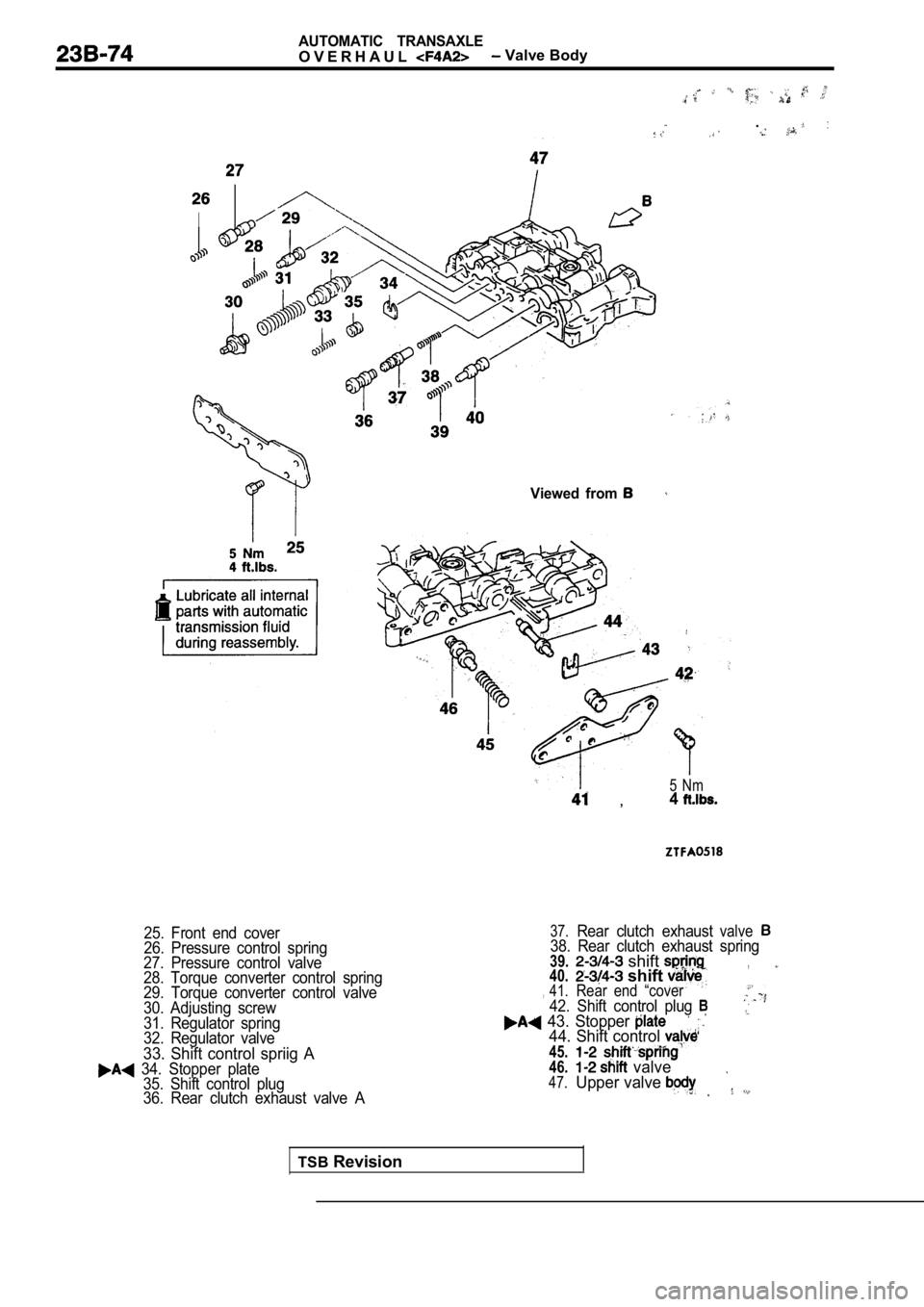
25. Front end cover
26. Pressure control spring
27. Pressure control valve
28. Torque converter control spring
29. Torque converter control valve
30. Adjusting screw
31. Regulator spring
32. Regulator valve
33. Shift control spriig A 34. Stopper plate 35. Shift control plug
36. Rear clutch exhaust valve A
5 Nm ,4
37.Rear clutch exhaustvalve38. Rear clutch exhaust spring39. shift ,40.41. shift Rear end “cover,42. Shift control plug 43. Stopper 44. Shift control
45.46. valve47.Upper valve
TSB Revision
Trending: battery, stop start, fuel pump, fuses, fuel cap, wiper fluid, wiper blades

