sensor MITSUBISHI SPYDER 1990 Service Repair Manual
[x] Cancel search | Manufacturer: MITSUBISHI, Model Year: 1990, Model line: SPYDER, Model: MITSUBISHI SPYDER 1990Pages: 2103, PDF Size: 68.98 MB
Page 593 of 2103
![MITSUBISHI SPYDER 1990 Service Repair Manual ENGINE (TURBO)
AND
ENGINE> Troubleshooting
INSPECTION PROCEDURE 17
Probable causeI
[Comment]l Malfunction of the system
Malfunction of the system is suspected.
Are diagnostic troubl MITSUBISHI SPYDER 1990 Service Repair Manual ENGINE (TURBO)
AND
ENGINE> Troubleshooting
INSPECTION PROCEDURE 17
Probable causeI
[Comment]l Malfunction of the system
Malfunction of the system is suspected.
Are diagnostic troubl](/img/19/57345/w960_57345-592.png)
ENGINE (TURBO)
AND
ENGINE> Troubleshooting
INSPECTION PROCEDURE 17
Probable causeI
[Comment]l Malfunction of the system
Malfunction of the system is suspected.
Are diagnostic trouble codes output
YESRefer to INSPECTION FOR DIAGNOSTICTROUBLE CODES.
Check theidle air control motor for operation sound Engine (Refer to Check the idle air control motor for operation soun d Engine>. (Refer to
SCAN TOOL Data list
14 Throttle position sensor (Refer to
OK
Check the idle control system malfunction (Refer t o INSPECTION PROCEDURE FOR DIAGNOSTIC TROUBLE CODE
Check the throttle position circuit malfunction (Refer to PROCEDURE FOR DIAGNOSTIC TROUBLE 20.)
NG,
SCAN TOOL Data list Check closed position switch system.
26 Closed throttle position switch (Refer to (Refer to INSPECTION PROCEDURE FOR DIAGNOSTICTROUBLE CODE .
. .
Clean the throttle valve area. (Refer to
INSPECTION PROCEDURE 18
Poor acceleration Probable cause I
[Comment]
Defective ignition system, abnormal air-fuel ratio, poor compression pressure, etc. are l Malfunction of the Ignition system Malfunction of air-fuel ratio control l Malfunction of the fuel supply system Poor acceleration
l C l o g g e d e x h a u s t s y s t e m
l Malfunction ‘of turbocharger system .
SCAN TOOL DTC
Are diagnostic trouble codes output
YESRefer to INSPECTION CHART FOR DIAGNOSTICTROUBLE CODES.
Check the injectors for opNG
(Refer to PROCEDURE FOR DIAGNOSTIC TROUBLE
OK
Check the ignition timing. Engine (Turbo)>
(Refer to GROUP A On-vehicle Service.)
Check the ignition timing. Engine>
Check that the crankshaft position sensor and timi ng belt cover are
installed
(Refer to GROUP On-vehicle Service.)
OK
Scan tool: Inspection when hesitation. stumble or poor acceleration occur. (Refer to INSPECTIONPROCEDURE 42.)I
OK
Check the fuel pressure. (Refer to
OK
Check the following items.
l Check the ignition coil, spark plugs, spark plug ca bles.
l Check supercharging pressure.
l Check intake charge pressure control system.
l Check rotating resistance of turbocharger turbine w heel. (Does the wheel rotate smoothly?)
l Check the compression pressure.
lCheck the fuel filter or fuel for clogging.
l Broken air intake hose
Clogged air cleaner
l Clogged exhaust system
Revision
Page 594 of 2103
ENGINE (TURBO)
AND ENGINE> Troubleshootina
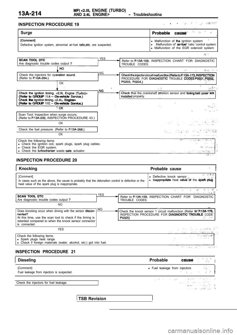
INSPECTION PROCEDURE 19
Surge
Defective ignition system, abnormal air-fuel are suspected.
, .
l Malfunction of ignition systeml Malfunction of’ ‘ratio ‘control system l Malfunction of the EGR solenoid system
Are diagnostic trouble codes output
YES ,
Refer to INSPECTION CHART FOR DIAGNOSTICTROUBLE CODES.
.
Check the injectors for opNG
(Refer to PROCEDURE FOR TROUBLE
OK
Check the ignition timing. Engine (Turbo)> Check that the crankshaft position sensor and are properly.(Refer to GROUP On-vehicle Service.)
Check the Engine>
(Refer to GROUP On-vehicle Service.)
Scan Tool: Inspection when surge occurs. (Refer to INSPECTION PROCEDURE 43.)
OK
Check the fuel pressure. (Refer to
OK
Check the following items.
l Check the ignition coil, spark plugs, spark plug ca bles.
l Check the EGR system.
l Check the
waste actuator.
INSPECTION PROCEDURE 20
Knocking Probable cause
[Comment]l Defective knock sensor ,
In cases such as the above, the cause is probably t hat the detonation control is defective or thel heat the
heat value of the spark plug is inappropriate.. .
YESRefer to INSPECTION CHART FOR’ ‘DIAGNOSTIC Are diagnostic trouble codes output TROUBLE CODES.
NO
NODoes knocking occur when driving with the sensor Check the knock sensor 1 circuit malfunction (Refe r INSPECTION PROCEDURE FOR CODE’At this time, use the scan tool to check if the timing isretarded compared to when the knock sensor connecto ris connected.
YES
Check the following items.
l Spark plugs heat range
l Check if foreign materials (water, alcohol, etc.) g ot into fuel.
INSPECTION PROCEDURE 21
DieselingProbableI
[Comment]
Fuel leakage from injectors is suspected.l Fuel leakage from injectors
Check the injectors for fuel leakage.
TSB Revision
Page 595 of 2103
![MITSUBISHI SPYDER 1990 Service Repair Manual ENGINE (TURBO)
AND ENGINE> Troubleshooting
INSPECTION PROCEDURE 22
Too high CO and HC concentration when idling
[Comment]Malfunction of the ratio
Abnormal air-fuel ratio is susp MITSUBISHI SPYDER 1990 Service Repair Manual ENGINE (TURBO)
AND ENGINE> Troubleshooting
INSPECTION PROCEDURE 22
Too high CO and HC concentration when idling
[Comment]Malfunction of the ratio
Abnormal air-fuel ratio is susp](/img/19/57345/w960_57345-594.png)
ENGINE (TURBO)
AND ENGINE> Troubleshooting
INSPECTION PROCEDURE 22
Too high CO and HC concentration when idling
[Comment]Malfunction of the ratio
Abnormal air-fuel ratio is suspected.
SCAN TOOL Are diagnostic trouble codes output
N O
YES Refer to INSPECTION CHART FOR DIAGNOSTICTROUBLE CODES.
Check the ignition timing. Engine (Turbo)>NG
(Refer to GROUP On-vehicle Service.) Check that the crankshaft position sensor and belt installedCheck the ignition timing. Engine>(Refer to GROUP 11 On-vehicle Service.)
OK
NGSCAN TOOL Data list
21 Engine coolant temperature sensor. Check the engine coolant temperature malfunction. (Refer to
(Refer to INSPECTION PROCEDURE FOR DIAGNOSTIC
TROUBLE CODES
OK
SCAN TOOL Data listNG Check the intake air temperature (Refer to
13 Intake air temperature sensor (Refer to INSPECTION PROCEDURE FOR DIAGNOSTIC
OK TROUBLE CODE
SCAN TOOL Data list
25 Barometric pressure sensor (Refer to
OK
Check the pressure circuit malfunction. INSPECTION PROCEDURE FOR DIAGNOSTIC TROUBLE CODE
SCAN TOOL Data listNGCheck the oxygen sensor circuit malfunction (bank sensor 2). (Refer59 Heated oxygen sensor (rear) (Refer to to INSPECTION PROCEDURE FOR DIAGNOSTIC
l Transaxle gear TROUBLE CODE ranae l Driving with the throttle wide open
O K :
OK
SCAN TOOL Data list NG
Heated oxygen sensor (front) (Refer to OK: 1,000 when racing suddenly
OK
SCAN TOOL Data list11 Heated oxygen sensor (front) (Refer to O K : and
Check the oxygen sensor circuit malfunction (bank 1 sensor 1). INSPECTION PROCEDURE FOR DIAGNOSTICTROUBLE CODE
alternately when idling.
NG
Check the fuel pressure. (Refer to
Check the following items.
l Check the injectors for operation sound.
l Check the injectors for fuel leakage.
l Check the ignition coil, spark plugs, spark plug ca bles.
l Check the compression pressure.
l Check the positive crankcase ventilation system.
l Check the evaporative emission control system.
l Check the
system.I
Check trouble symptom.
Replace the three-way converter.
TSB Revision
Page 597 of 2103
![MITSUBISHI SPYDER 1990 Service Repair Manual ENGINE (TURBO)
AND ENGINE> Troubleshoot&j
INSPECTION PROCEDURE 24
Transient, mass emission tailpipe test test failed
[Comment]
The test is failed if the air/fuel ratio is not co MITSUBISHI SPYDER 1990 Service Repair Manual ENGINE (TURBO)
AND ENGINE> Troubleshoot&j
INSPECTION PROCEDURE 24
Transient, mass emission tailpipe test test failed
[Comment]
The test is failed if the air/fuel ratio is not co](/img/19/57345/w960_57345-596.png)
ENGINE (TURBO)
AND ENGINE> Troubleshoot&j
INSPECTION PROCEDURE 24
Transient, mass emission tailpipe test test failed
[Comment]
The test is failed if the air/fuel ratio is not con trolled to the theoretical air/fuel ratio by means of
the feedback control from the oxygen sensor signal, if the EGR flow volume is insufficient, or if
the catalyst has deteriorated.
Probable cause1
NOTE
If the temperature of the three-way catalyst is low when the exhaust gas is tested, the three-way
cannot effectively clean the exhaust. Accordingly, the engine needs to be sufficiently warmed
the exhaust gas is tested, and the gas should then be tested immediately.
Revision
Page 598 of 2103
ENGINE (TURBO)
AND ENGINE> Troubleshooting
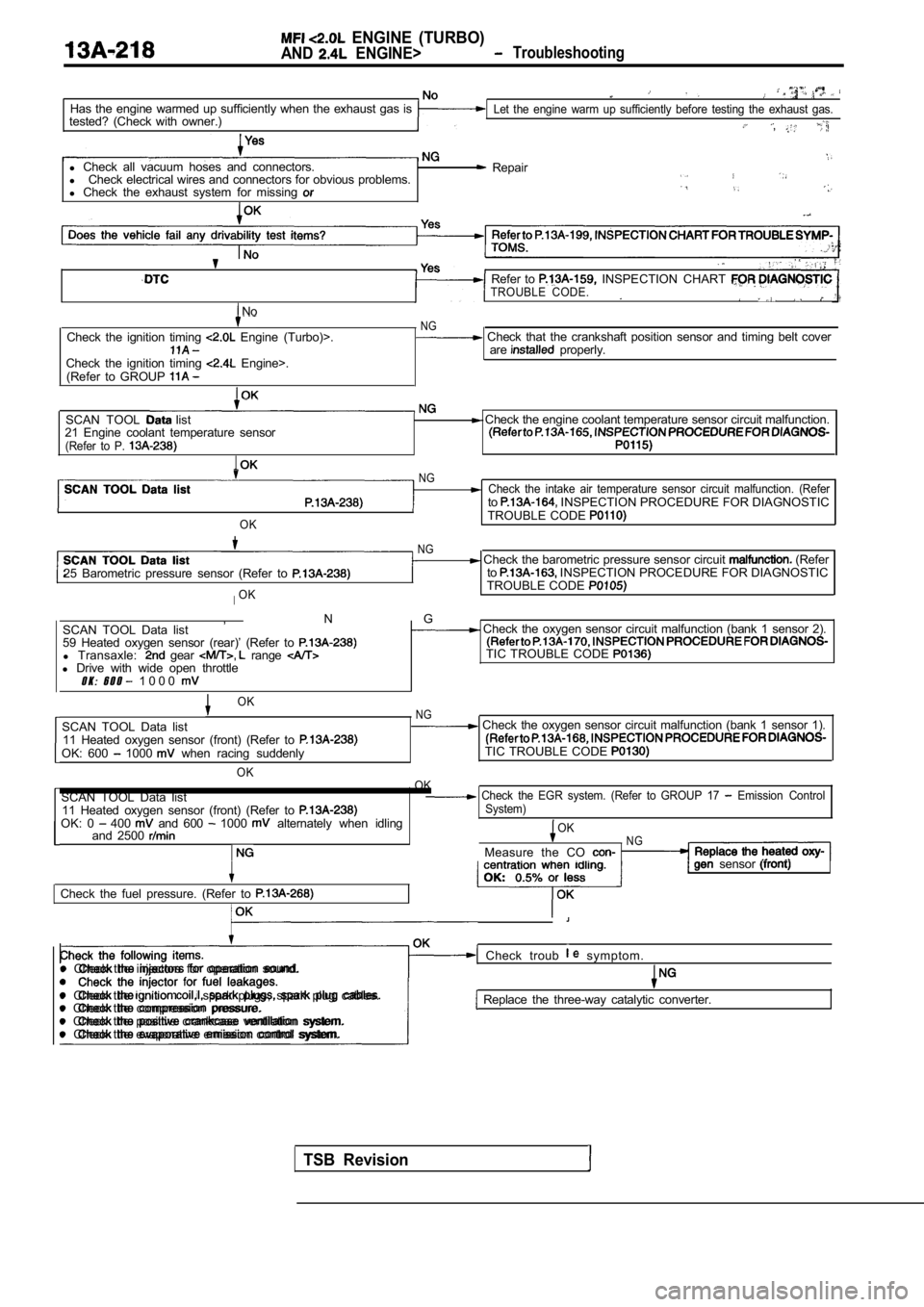
Has the engine warmed up sufficiently when the exhaust gas is
tested? (Check with owner.)Let the engine warm up sufficiently before testing the exhaust gas.
,
l Check all vacuum hoses and connectors.
l Check electrical wires and connectors for obvious p roblems.
l Check the exhaust system for missing Repair
No
Check the ignition timing Engine (Turbo)>.
Check the ignition timing Engine>.
(Refer to GROUP
Refer to INSPECTION CHART TROUBLE CODE.
NG Check that the crankshaft position sensor and timi ng belt cover
are properly.
SCAN TOOL list
21 Engine coolant temperature sensor
(Refer to P.
Check the engine coolant temperature sensor circui t malfunction.
OK
NGCheck the intake air temperature sensor circuit mal function. (Referto INSPECTION PROCEDURE FOR DIAGNOSTIC
TROUBLE CODE
25 Barometric pressure sensor (Refer to
IOK
NG Check the barometric pressure sensor circuit (Refer
to INSPECTION PROCEDURE FOR DIAGNOSTIC
TROUBLE CODE
, N G
SCAN TOOL Data list Check the oxygen sensor circuit malfunction (bank 1 sensor 2).
59 Heated oxygen sensor (rear)’ (Refer to
l Transaxle: gear range TIC TROUBLE CODE l Drive with wide open throttleO K : 6 0 0 1 0 0 0
TSB Revision
OKNGSCAN TOOL Data list Check the oxygen sensor circuit malfunction (bank 1 sensor 1).
11 Heated oxygen sensor (front) (Refer to
OK: 600 1000 when racing suddenly TIC TROUBLE CODE
OK
OK
SCAN TOOL Data list Check the EGR system. (Refer to GROUP 17 Emission Control11 Heated oxygen sensor (front) (Refer to System)OK: 0 400 and 600 1000 alternately when idling
and 2500 OKNGMeasure the CO
Check the fuel pressure. (Refer to
sensor
l Check the injector for fuel leakages.
Check troub symptom. l Check the injectors for operation sound.
l Check the
spark plugs, spark plug cables.l Check the compression pressure. Replace the three-way catalytic converter.
l Check the positive crankcase ventilation system.
l Check the evaporative emission control system.
Page 600 of 2103
![MITSUBISHI SPYDER 1990 Service Repair Manual ENGINE (TURBO)
AND ENGINE>
INSPECTION PROCEDURE 27
Power supply system and ignition systemP r o b a b l e
[Comment]l Malfunction of the ignition switchWhen an ignition switch ON sign MITSUBISHI SPYDER 1990 Service Repair Manual ENGINE (TURBO)
AND ENGINE>
INSPECTION PROCEDURE 27
Power supply system and ignition systemP r o b a b l e
[Comment]l Malfunction of the ignition switchWhen an ignition switch ON sign](/img/19/57345/w960_57345-599.png)
ENGINE (TURBO)
AND ENGINE>
INSPECTION PROCEDURE 27
Power supply system and ignition systemP r o b a b l e
[Comment]l Malfunction of the ignition switchWhen an ignition switch ON signal is input to the E CM, the ECM turns the relay ON. Thisl Malfunction of the relaycauses battery positive voltage to be supplied to t he injectors and volume air flow sensor.Improper connector contact, open or
short-circuited harness wire
l .-Disconnected
wirel Malfunction of the ECM
Check the
relay. (Refer to Replace
OK NG
Measure at the relay connector Check the harness wire battery and lDisconnect the connector, and measure at the harnes sRepair, if necessary.side.l between 3, 4 and aroundOK: Battery positive voltage
OK
Check the ECM power and around circuit. ( R e f e r PR O C E D U R E 4 4 . )
INSPECTION PROCEDURE 28
Fuel pump system Engine (Turbo)>Probable cause
[Comment]l Malfunction of the fuel pump relay The ECM turns the fuel pump relay ON when the engin e is cranking or running, and this M a l f u n c t i o n o f ,
plies power to drive the fuel pump. Improper connector open short-circuited harness wire
l Malfunction of the
Check the fuel pump circuit.
(Refer to I N S P E C T I O N P R O C E D U R E .
Replace
OK .
Check the fuel pump drive control circuit.
Connect the connector. (Refer to INSPECTION PROCEDURE 46.)
l Voltage between 1 and ground
l SCAN TOOL Actuator test: Fuel pump drive
OK:
oositive voltaae
OK
Check the harness wire between fuel pump relay conn ectorand fuel pump drive terminal. Repair, if necessary.
TSB Revision
Page 607 of 2103
![MITSUBISHI SPYDER 1990 Service Repair Manual ENGINE (TURBO)
AND
ENGINE> Troubleshooting
INSPECTION PROCEDURE 35
Idle air control motor (DC motor) Engine>P r o b a b l e c a u s e
[Comment]l Malfunction of idle air control mo MITSUBISHI SPYDER 1990 Service Repair Manual ENGINE (TURBO)
AND
ENGINE> Troubleshooting
INSPECTION PROCEDURE 35
Idle air control motor (DC motor) Engine>P r o b a b l e c a u s e
[Comment]l Malfunction of idle air control mo](/img/19/57345/w960_57345-606.png)
ENGINE (TURBO)
AND
ENGINE> Troubleshooting
INSPECTION PROCEDURE 35
Idle air control motor (DC motor) Engine>P r o b a b l e c a u s e
[Comment]l Malfunction of idle air control motor
The ECM controls the intake air volume during idlin g by opening and closing the I m p r o p e r c o n n e c t o r open “circuit’ servo valve located in the bypass passage.
l Malfunction of the
at the idle air control motor connector Connect the connector. (Use test harness: Voltage between 5 and ground (Ignition switch: ON)
OK: 2 or more to 0 (momentarily) Voltage between 6 and ground (Ignition switch: ON)OK: 4 or more to 0 (momentarily)
OK
the idle air control motor.1
Check symptom.
Replace
INSPECTION PROCEDURE 36
Scan tool: Inspection when no initial combustion oc curs
SCAN TOOL Data listNGCheck the power and ignition 16 Voltage of ECM power source (Refer to (Refer to I PROCEDURE 27.)
(Whenoil filler cap is removed.)
SCAN TOOL DTC
Are the diagnostic trouble codes output
Check timing belt for breakage.
INSPECTION CHART FOR TROUBLE CODES.
(Refer to
SCAN TOOL list NG
22 Crankshaft position sensor OK: Cranking speed is displayed.
OK
Check the crankshaft position sensor circuit malfu nction. (Refer to INSPECTION PROCEDURE FOR DIAGNOSTIC
TROUBLE CODES
SCAN TOOL Actuator testCheck the fuel pump system Engine 07 Fuel pump (Refer to (Refer to INSPECTION PROCEDURE 28.)
OKCheck the fuel pump system (Refer to INSPECTION PROCEDURE 29) .
SCAN TOOL list21 Check the engine coolant temperature circuit (Refer to INSPECTION PROCEDURE FOR DIAGNOSTICTROUBLE CODES
TSB Revision
Page 608 of 2103
ENGINE (TURBO)
AND ENGINE> Troubleshooting
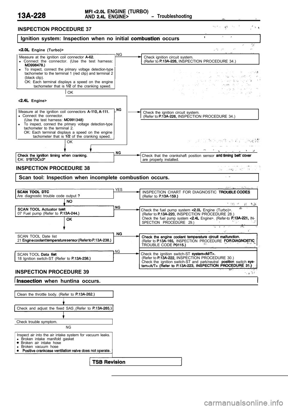
INSPECTION PROCEDURE 37 ,
Ignition system: Inspection when no initial occurs,
Engine (Turbo)> NGMeasure at the ignition coil connector Check ignition circuit system.
l Connect the connector. (Use the test harness:
(Refer to INSPECTION PROCEDURE 34.)
lTo inspect, connect the primary voltage detection-typetachometer to the terminal 1 (red clip) and terminal 2
(black clip).
OK: Each terminal displays a speed on the engine tachometer that is
of the cranking speed.
OK
Engine>
Measure at the ignition coil connectors
l Connect the connector.
(Use the test harness:
lTo inspect, connect the primary voltage detection-t ypetachometer to the terminal 2.OK: Each terminal displays a speed on the engine
tachometer that is of the cranking speed.
OK
NGCheck the ignition circuit system.(Refer to INSPECTION PROCEDURE 34.)
OK:
NG Check that the crankshaft position sensor are properly installed.
INSPECTION PROCEDURE 38
Scan tool: Inspection when incomplete combustion oc curs.
YESINSPECTION CHART FOR DIAGNOSTIC Arediagnostic trouble code output (Refer to
SCAN TOOL Actuator te
07 Fuel pump (Refer toNG, Check the fuel pump system Engine (Turbo)>.(Refer to INSPECTION PROCEDURE 28.)Check the fuel pump system Engine>. (Refer-to IN-
SPECTION PROCEDURE 29.)
./I,’
SCAN TOOL Date list21(Refer to INSPECTION PROCEDURE TROUBLE CODE
NGSCAN TOOL Data Check the ignition switch-ST 18 Ignition switch-ST (Refer to (Refer to INSPECTION PROCEDURE 30.)
Check the ignition switch-ST andpark/neutralswitch
INSPECTION PROCEDURE 39 ,
when huntina occurs.
Clean the throttle body. (Refer to
I
Check and adiust the fixed SAS (Refer to
Check trouble symptom.
NG
Inspect air into the air intake system for vacuum l eaks.
l Broken intake manifold gasket
Broken air intake hose
l Broken vacuum hose
Page 609 of 2103
ENGINE (TURBO)
AND. ENGINE> Troubleshooting . ,
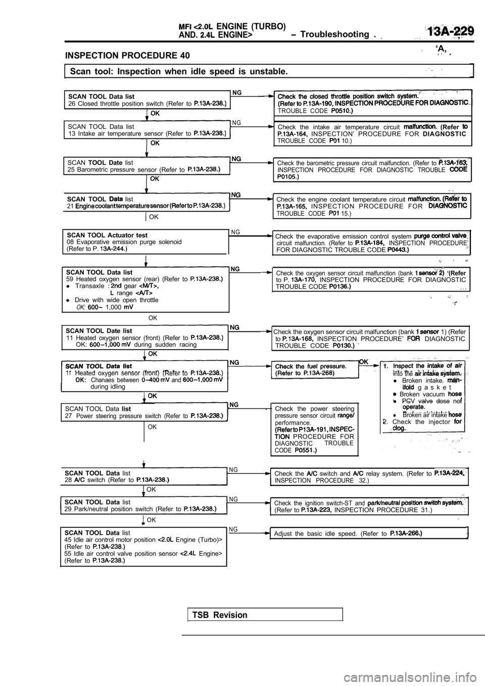
INSPECTION PROCEDURE 40
‘A, .
Scan tool: Inspection when idle speed is unstable.
SCAN TOOL Data list
NG
26 Closed throttle position switch (Refer to TROUBLE CODE
SCAN TOOL Data listNG Check the intake air temperature circuit (Refer 13 Intake air temperature sensor (Refer to INSPECTION’ PROCEDURE FOR DIAGNOSTICTROUBLE CODE 10.)
SCANTOOL Date listCheck the barometric pressure circuit malfunction. (Refer to 25 Barometric pressure
sensor (Refer toINSPECTION PROCEDURE FOR DIAGNOSTIC TROUBLE
.
SCAN TOOL list Check the engine coolant temperature circuit 21 I N S P E C T I O N P R O C E D U R E F O R
OKTROUBLE CODE 15.)
SCAN TOOL Actuator test
08 Evaporative emission purge solenoid
(Refer to P. NG Check the evaporative emission control system circuit malfunction. (Refer to INSPECTION PROCEDURE’FOR DIAGNOSTIC TROUBLE CODE
SCAN TOOL Data listNG
59 Heated oxygen sensor (rear) (Refer to l Transaxle gear range l Drive with wide open throttleOK: 1,000
OK
SCAN TOOL Date list11 Heated oxygen sensor (front) (Refer to OK: during sudden racing
Check the oxygen sensor circuit malfunction (bank ‘(Referto P. INSPECTION PROCEDURE FOR DIAGNOSTIC
TROUBLE CODE
Check the oxygen sensor circuit malfunction (bank 1) (Refer
to INSPECTION PROCEDURE’ DIAGNOSTIC
TROUBLE CODE
11Heated oxygen sensor (front) (Refer toOK:Chanaes between and during idlingI
SCAN TOOL Data listNG.
27
Power steering pressure switch (Refer to
OK
Check the power steeringpressure sensor circuit performance.
PROCEDURE FORDIAGNOSTIC TROUBLE
CODE
into the l Broken intake. g a s k e t Broken vacuum l PCV valve dose not
lBroken air intake 2. Check the injector
SCAN TOOL Data list
28 switch (Refer to
OK
N GCheck the switch and relay system. (Refer to INSPECTION PROCEDURE 32.)
SCAN TOOL Data listN G
29 Park/neutral position switch (Refer to Check the ignition switch-ST and (Refer to INSPECTION PROCEDURE 31.)
OK
SCAN TOOL Data list
45 Idle air control motor position Engine (Turbo)>
(Refer to
55 Idle air control valve position sensor Engine>
(Refer to
NGAdjust the basic idle speed. (Refer to
TSB Revision
Page 618 of 2103
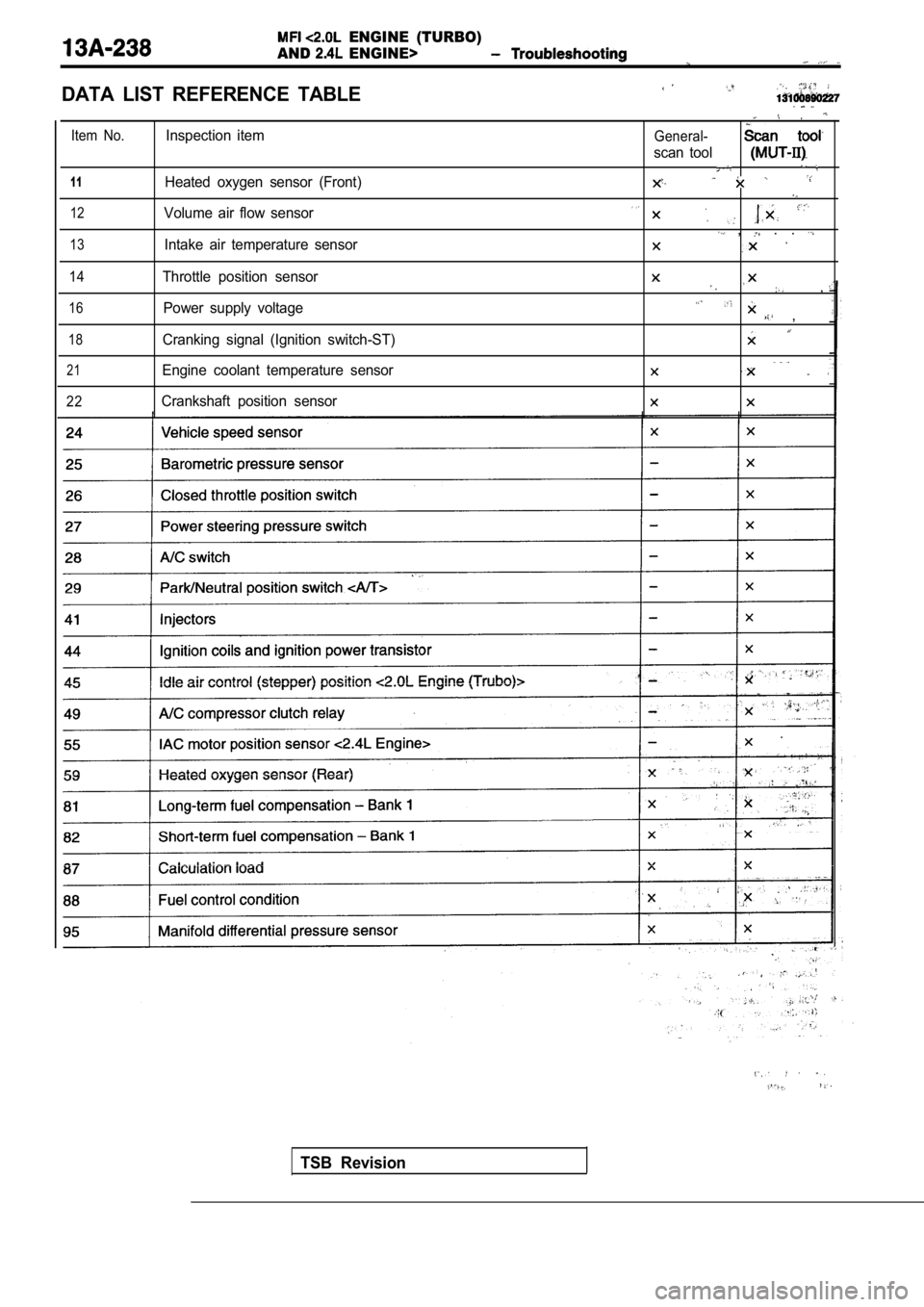
ENGINE (TURBO)
AND
ENGINE>
DATA LIST REFERENCE TABLE
Item No.
1 1
12
13
14
16
18
21
22
Inspection item
Heated oxygen sensor (Front)
Volume air flow sensor
Intake air temperature sensor
Throttle position sensor Power supply voltage
Cranking signal (Ignition switch-ST)
Engine coolant temperature sensor
Crankshaft position sensorGeneral-
scan tool
, . .
,
,
TSB Revision