belt MITSUBISHI SPYDER 1990 Service User Guide
[x] Cancel search | Manufacturer: MITSUBISHI, Model Year: 1990, Model line: SPYDER, Model: MITSUBISHI SPYDER 1990Pages: 2103, PDF Size: 68.98 MB
Page 74 of 2103
ENGINE On-vehicle Service
Timing belt side
.
2.Start the engine and perform gentle racing* several times
(less than times.)
If the abnormal noise stops by racing, the air is b led
from the high pressure chamber of the lash adjusters
and the function of the lash adjusters is normalized.
After raising the engine speed from idling to 3000
gradually (in 30 seconds), drop the
ally (in 30 seconds) to idling.
NOTE
lIf the vehicle is parked on a slope for the oil
in the lash adjusters will be decreased ‘andairmay
enter the high pressure chamber when the
is started.
lAfter the vehicle is parked for long, air may enter
the high pressure chamber because the, oil in the
oil passage will be gone and, it will take a time b efore
the oil is supplied to the lash adjusters.
3.If an abnormal noise does not stop by racing, check the
lash adjusters according to the following procedure s.
Stop the engine.
(2)Set the NG. cylinder of the engine to the compression
top dead center.
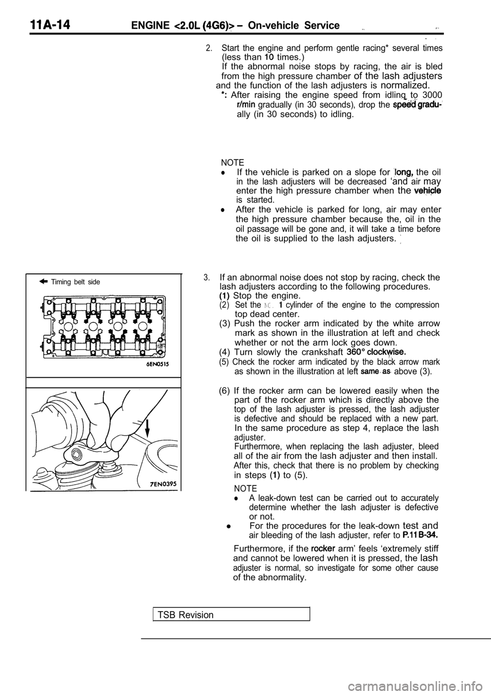
(3) Push the rocker arm indicated by the white arro w
mark as shown in the illustration at left and check
whether or not the arm lock goes down.
(4) Turn slowly the crankshaft
(5) Check the rocker arm indicated by the black arr ow mark
as shown in the illustration at left above (3).
(6) If the rocker arm can be lowered easily when th e
part of the rocker arm which is directly above the
top of the lash adjuster is pressed, the lash adjus ter
is defective and should be replaced with a new part .
In the same procedure as step 4, replace the lash
adjuster.
Furthermore, when replacing the lash adjuster, bleed
all of the air from the lash adjuster and then install.
After this, check that there is no problem by check ing
in steps to (5).
NOTE
lA leak-down test can be carried out to accurately
determine whether the lash adjuster is defective
or not.
l For the procedures for the leak-down test and
air bleeding of the lash adjuster, refer to
Furthermore, if the arm’ feels ‘extremely stiff
and cannot be lowered when it is pressed, the lash
adjuster is normal, so investigate for some other c ause
of the abnormality.
TSB Revision
Page 76 of 2103
ENGINE Engine
ENGINE ASSEMBLY
REMOVAL AND INSTALLATION
Operationl Fuel Line Pressure Releasing(Refer to GROUP On-vehicle Service.)l ‘Hood Removall Engine Coolant DrainingRefer to GROUP 00 Maintenance Service.)l Assembly Removal Refer to GROUP TransaxleA Refer to GROUP Transaxle
Refer to GROUP Transaxle
Refer to GROUP TransaxleAssembly.)lRadiator Removal (Refer to GROUP 14 Radiator.)l Under Cover Removal (Refer to GROUP 42 Under Cover.)
6
2216
Operationl Radiator Installation(Refer to GROUP 14 Radiator.)l Transaxle Assembly Removal Refer to GROUP Assembly.) Refer to GROUP Transaxle
Refer to GROUP Transaxle
Refer to GROUP
Transaxle
l Engineoolant(Refer to GROUP 00 l Hoodl Accelerator Cable Adjustment(Refer to GROUP 17 l Under Cover Installation(Refer to GROUP 42 Under l Drive Belt Adjustment
34
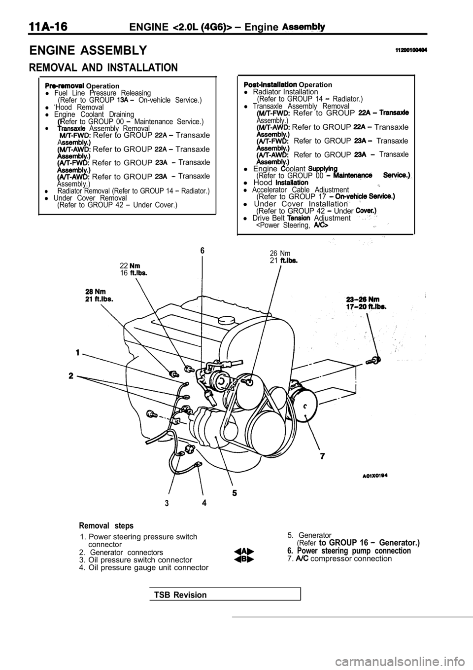
Removal steps
1. Power steering pressure switchconnector
2. Generator connectors
3. Oil pressure switch connector
4. Oil pressure gauge unit connector
5. Generator(Referto GROUP 16 Generator.)
6. Power steering pump connection7. compressor connection
TSB Revision
Page 81 of 2103
ENGINE Crankshaft
CRANKSHAFT PULLEY
REMOVAL AND INSTALLATION
l Under Cover Removal(Refer to GROUP 42 Under Cover.)(Refer to Under
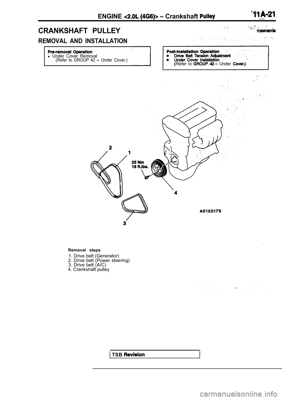
Removal steps1. Drive belt (Generator)
2. Drive belt (Power steering) 3. Drive belt (A/C)
4. Crankshaft pulley
TSB
Page 82 of 2103
ENGINECamshaft and Oil Seal
CAMSHAFT AND CAMSHAFT OIL SEAL
REMOVAL AND INSTALLATION
Operation,l Timing Belt Front Upper Cover Removal
(Refer to P o s t - i n s t a l l a t i o n O p e r a t i o n l Timing Belt Front Cover (Refer to l Engine
2.9 Nm2.2
3.4Nm2.5
Nm
Enaine oil
TSB Revision
2 in.)
Sealant:MITSUBISHI GENUINE PART or equivalent
Cylinder head
sealant: ATD No. 8660 or equivalent
Page 83 of 2103
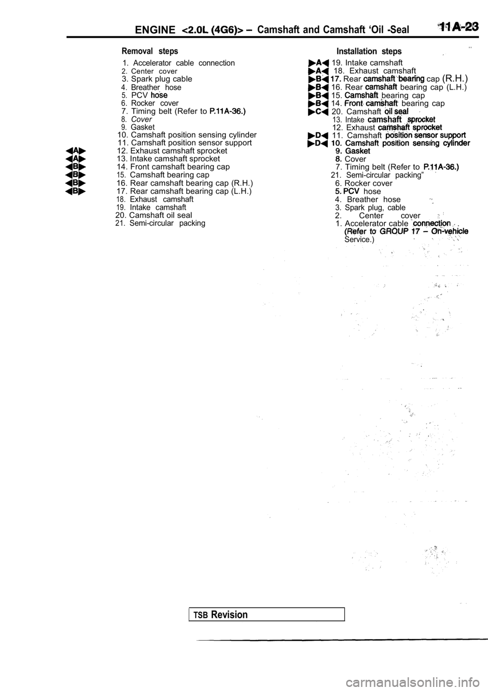
ENGINECamshaft and Camshaft ‘Oil -Seal
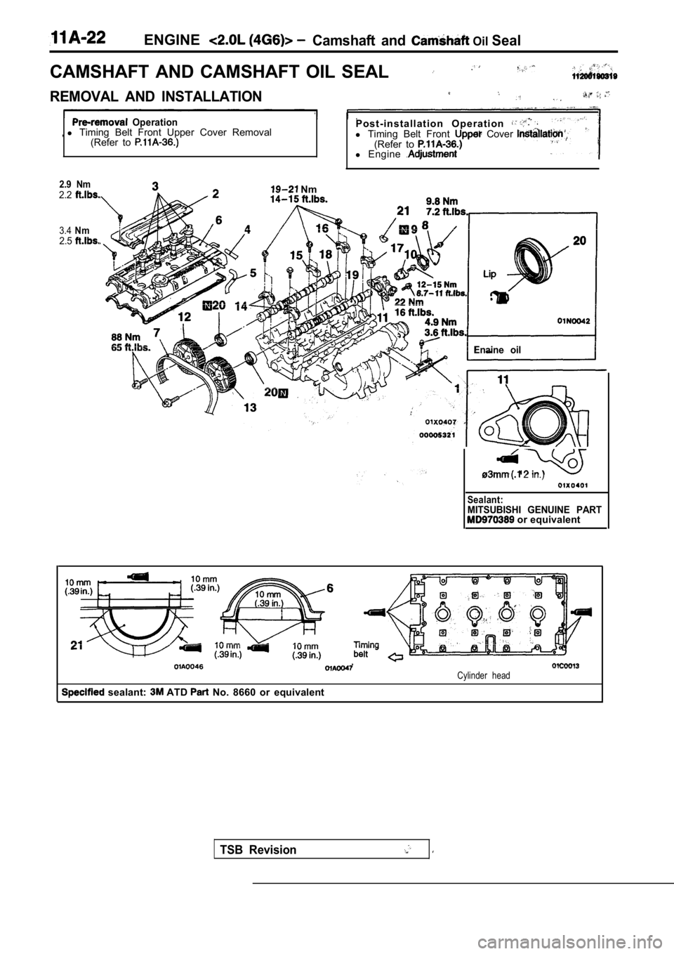
Removal steps
1. Accelerator cable connection2.Center cover
3. Spark plug cable
4.Breather hose5.PCV6.Rocker cover7. Timing belt (Refer to 8.Cover9.Gasket10. Camshaft position sensing cylinder 11. Camshaft position sensor support
12. Exhaust camshaft sprocket
13. Intake camshaft sprocket
14. Front camshaft bearing cap
15.Camshaft bearing cap
16. Rear camshaft bearing cap (R.H.)
17. Rear camshaft bearing cap (L.H.)
18.Exhaust camshaft19.Intake camshaft20. Camshaft oil seal21.Semi-circular packing
Installation steps. .
19. Intake camshaft 18. Exhaust camshaft Rear cap (R.H.)
16. Rear bearing cap (L.H.)
15. bearing cap 14. bearing cap
20. Camshaft 13. Intake camshaft12. Exhaust 11. Camshaft
Cover
7. Timing belt (Refer to
21. Semi-circular packing”
6. Rocker cover hose
4. Breather hose
3. Spark plug, cable2. Center cover 1. Accelerator cable .
Service.)
TSBRevision
Page 88 of 2103
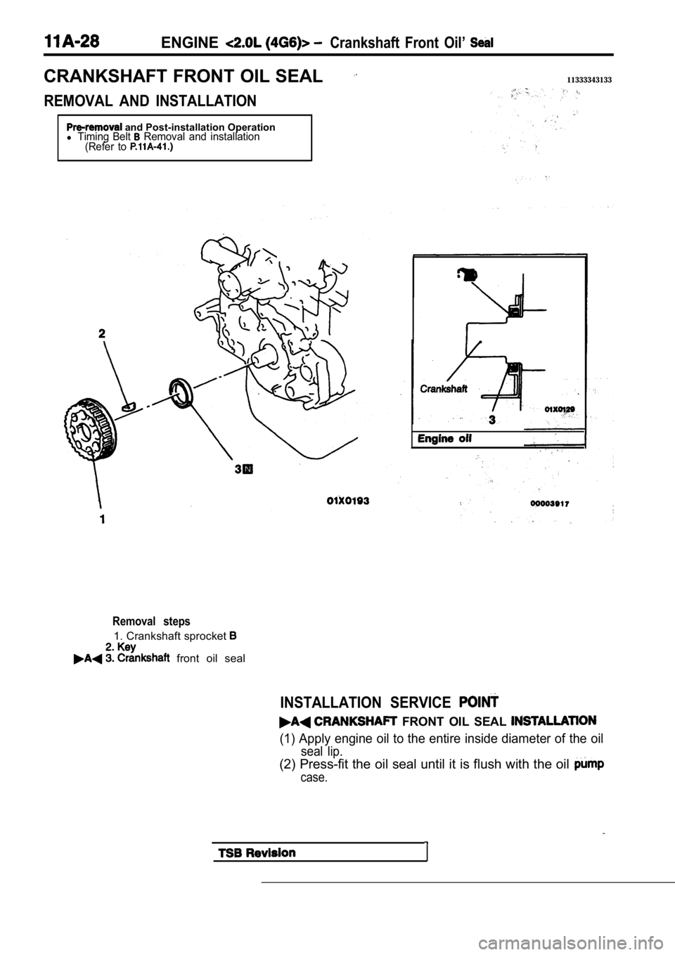
ENGINECrankshaft Front Oil’
CRANKSHAFT FRONT OIL SEAL11333343133
REMOVAL AND INSTALLATION
and Post-installation Operationl Timing Belt Removal and installation
(Refer to
Removal steps
1. Crankshaft sprocket
front oil seal
INSTALLATION SERVICE
FRONT OIL SEAL
(1) Apply engine oil to the entire inside diameter of the oil
seal lip.
(2) Press-fit the oil seal until it is flush with the oil
case.
Page 92 of 2103
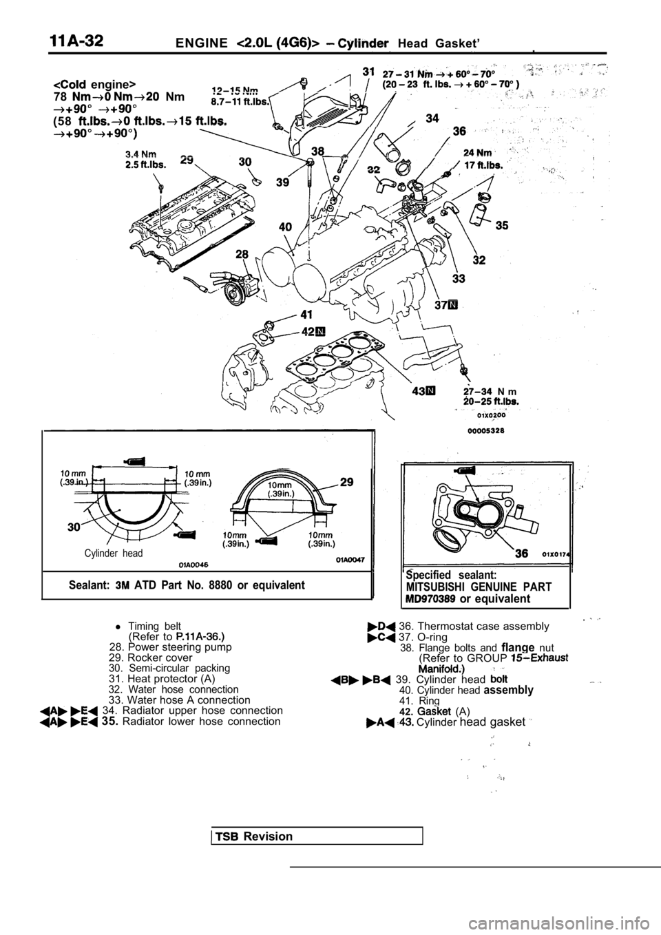
ENGINE Head Gasket’.
engine>
78
Nm
(58
N m
Cylinder head
Sealant: ATD Part No. 8880 or equivalent
Revision
Specified sealant: MITSUBISHI GENUINE PART
or equivalent
36. Thermostat case assembly 37. O-ring38. Flange bolts and flangenut(Refer to GROUP
39. Cylinder head 40. Cylinder head assembly41. Ring42. (A) Cylinder head gasket
l Timing belt(Refer to 28. Power steering pump
29. Rocker cover
30. Semi-circular packing31. Heat protector (A)32. Water hose connection33. Water hose A connection 34. Radiator upper hose connection 35. Radiator lower hose connection
Page 96 of 2103
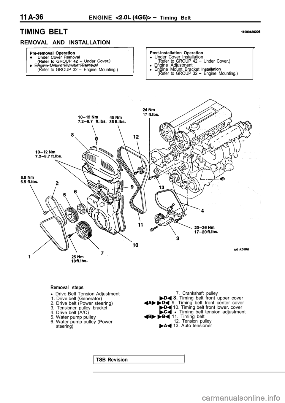
E N G I N E Timing Belt
TIMING BELT
REMOVAL AND INSTALLATION
l Engine Mount Bracket Removal(Refer to GROUP 32 Engine Mounting.)
Post-installation Operationl Under Cover Installation(Refer to GROUP 42 Under Cover.)l Engine Adjustmentl Engine Mount Bracket (Refer to GROUP 32 Engine Mounting.)
4817
6.86.52
25
Removal steps
l Drive Belt Tension Adjustment
1. Drive belt (Generator)
2. Drive belt (Power steering)
3. Tensioner pulley bracket4. Drive belt (A/C)
5. Water pump pulley
6. Water pump pulley (Power
steering)
7. Crankshaft pulley 8. Timing belt front upper cover 9. Timing belt front center cover 10. Timing belt front lower. cover l Timing belt tension adjustment 11. Timing belt12. Tension pulley 13. Auto tensioner
TSB Revision
Page 97 of 2103
ENGINE Timing
(22-44
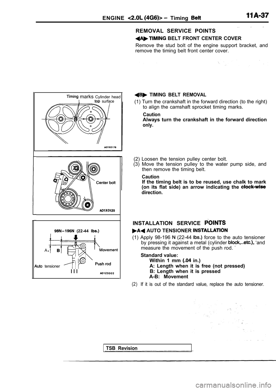
A
tensioner
marks Cylinder headI surface
I I I
REMOVAL SERVICE POINTS
BELT FRONT CENTER COVER
Remove the stud bolt of the engine support bracket, and
remove the timing belt front center cover.
TIMING BELT REMOVAL
(1) Turn the crankshaft in the forward direction (t o the right)
to align the camshaft sprocket timing marks.
Caution
Always turn the crankshaft in the forward direction
only.
(2) Loosen the tension pulley center bolt.
(3) Move the tension pulley to the water pump side, and
then remove the timing belt.
Caution
If the timing belt is to be reused, use chalk to ma rk
(on its flat side) an arrow indicating the
direction.
INSTALLATION SERVICE
AUTO TENSIONER
(1) Apply 98-196 (22-44 force to the auto tensioner
by pressing it against a metal (cylinder
‘and
measure the movement of the push rod.
Standard value: Within 1 mm
in.)
A: Length when it is free (not pressed) B: Length when it is pressed
A-B: Movement
(2)If it is out of the standard value, replace the aut o tensioner.
TSB Revision
Page 98 of 2103
ENGINE Timing Belt
,Set pin
I
Timing marksCylinder had
Itop surface
Crankshaft
sprocket
60 mm
60 mm
(2.36 in.)
(2.36 in.)
or more
or more in.) in.)
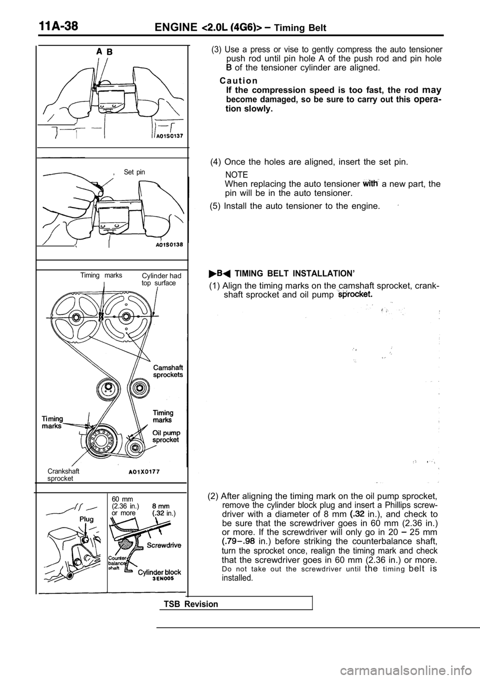
(3) Use a press or vise to gently compress the auto tensioner
push rod until pin hole A of the push rod and pin hole
of the tensioner cylinder are aligned.
C a u t i o n If the compression speed is too fast, the rod may
become damaged, so be sure to carry out this opera-
tion slowly.
(4) Once the holes are aligned, insert the set pin.
NOTE
When replacing the auto tensioner a new part, the
pin will be in the auto tensioner.
(5) Install the auto tensioner to the engine.
TIMING BELT INSTALLATION’
(1) Align the timing marks on the camshaft sprocket , crank-
shaft sprocket and oil pump
(2) After aligning the timing mark on the oil pump sprocket,
remove the cylinder block plug and insert a Phillips screw-
driver with a diameter of 8 mm in.), and check to
be sure that the screwdriver goes in 60 mm (2.36 in .)
or more. If the screwdriver will only go in 20
25 mm
in.) before striking the counterbalance shaft,
turn the sprocket once, realign the timing mark and check
that the screwdriver goes in 60 mm (2.36 in.) or mo re.
Do not take out the screwdriver until thet i m i n g b e l t i s
installed.
TSB Revision