oil temperature MITSUBISHI SPYDER 1990 Service Owner's Guide
[x] Cancel search | Manufacturer: MITSUBISHI, Model Year: 1990, Model line: SPYDER, Model: MITSUBISHI SPYDER 1990Pages: 2103, PDF Size: 68.98 MB
Page 441 of 2103
![MITSUBISHI SPYDER 1990 Service Owners Guide ENGINE (NON-TURBO)>
Scan tool 106
Code General scan tool
No.Multiple Cylinder Mlsfire
43
[Comment]Background
l Excessive engine misfire results in increased catal yst temperature.](/img/19/57345/w960_57345-440.png "MITSUBISHI SPYDER 1990 Service Owners Guide ENGINE (NON-TURBO)>
Scan tool 106
Code General scan tool
No.Multiple Cylinder Mlsfire
43
[Comment]Background
l Excessive engine misfire results in increased catal yst temperature.")
ENGINE (NON-TURBO)>
Scan tool 106
Code General scan tool
No.Multiple Cylinder Mlsfire
43
[Comment]Background
l Excessive engine misfire results in increased catal yst temperature.
l Severe misfire could cause catalyst damage.
l To prevent catalytic converter damage, the PCM moni tors engine misfire.
l The PCM monitors for misfire during most engine ope rating conditions.
lWhen a misfire is detected, the PCM stores a diagnostic trouble code and causes the to either flash or illuminate continuously during active misfire.
Range of Check
l MAP voltage is less than 1.60
l Engine speed is between 2200 and 2800 l Engine coolant temperature is greater than l Vehicle speed less than Set Condition
l 1000 Rev Misfire
The PCM detects misfire in more than 1.6% of the en gine cycles in a 1000 revolution
period.l 200 Rev MisfireThe PCM detects misfire in more than 15% of the eng ine cycles in a 200 revolution period.
.
Spark plugs or wires failed
l Ignition coil failed
l Crankshaft position piston rings v a l v e s
l Head gasket failed
l C r a c k e d
l Fuel lines and filter failed
l Fuel failed
l failed
l Wiring and connectors failed
l Engine coolant
l Timing belt tooth broken,
l EGR
SCAN TOOL SENSOR READ TESTS (Data list)
05 Engine coolant temperature sensor (Refer to Check the engine coolant temperature circuit.
(Refer to INSPECTION PROCEDURE 38.)
OK
SCAN TOOL SENSOR READ TESTS (Data list)
27 Intake air temperature sensor (Refer to
OK
Check the intake air temperaturecircuit.(Refer to INSPECTION PROCEDURE
SCAN TOOL SENSOR READ TESTS (Data list)
11 MAP sensor reading (Refer to
OK
OK
Check the MAP sensor circuit.(Refer to INSPECTION PROCEDURE 40.)
SCAN TOOL SENSOR READ TESTS (Data list)
Check the following connectors: 66 Oxygen sensor volts (front) (Refer to OK: Repeat and alternately whenidling.
Check the fuel pressure. (Refer to Check the harness wire between the PCM and the cran kshaft
position sensor connector.
l Check the injectors for operation sound.
l Check the injectors for fuel leakage.
l Check the evaporative emission control system.
Check the following items.
l Check the ignition coil, spark plug cables.
l Check the compression pressure.
Check the EGR
TSB Revision
Page 454 of 2103
![MITSUBISHI SPYDER 1990 Service Owners Guide ENGINE Troubleshooting .
Scan tool 138
Code General scan tool
No. Not
25
[Comment]Range of Check
l Engine:
l Vehicle at rest and the brake appliedSet Conditionl speed differ](/img/19/57345/w960_57345-453.png "MITSUBISHI SPYDER 1990 Service Owners Guide ENGINE Troubleshooting .
Scan tool 138
Code General scan tool
No. Not
25
[Comment]Range of Check
l Engine:
l Vehicle at rest and the brake appliedSet Conditionl speed differ")
ENGINE Troubleshooting .
Scan tool 138
Code General scan tool
No. Not
25
[Comment]Range of Check
l Engine:
l Vehicle at rest and the brake appliedSet Conditionl speed differs from target idle by 200 for 12 seconds. l
Idle air control motor failed
l motor related circuit .
SCAN TOOL SENSOR READ TESTS (Data list)
12 position (Refer to Check the air control motor. (Refer to
OK
Check the throttle body minimum air flow. (Refer to
Code
No. R e l a y
General scan tool High Speed Radiator Fan Control
[Comment]
Background
lThe high speed radiator fan relay controls the high speed operation of the radiator fan.lOne side of the relay control coil is supplied with 12 volts when the switch is
turned to the ON position.
lThe circuit is completed when the other side of the relay coil is grounded by the PCM.lThe PCM grounds the relay control circuit depending on engine coolant temperature and/or A/C compressor condition, etc.
Range of Check
l Battery voltage: 10
or more
l Ignition switch: ON
Set Condition
lAn open or shorted condition is detected in the hig h speed radiator fan relay control circuitfor 3 seconds.
Probable cause
TSB Revision
l Relay open or l Ignition switch output lLow speed radiator fan relay control circuit
open or shorted
NGMeasure at the PCM connector Check the radiator fan circuit.lDisconnect the connector, and measure at harness side. Voltage between 69 and ground(Ignition switch: ON),.
OK: Battery positive voltage .,
l
Connect a jumper wire between 69 and ground(Ignition switch: ON)
OK: Radiator fan runs at high speed.
OK
Check the following connector: N G Repair
OK
Check trouble symptom.1
NG
Replace the PCM.
Page 477 of 2103
![MITSUBISHI SPYDER 1990 Service Owners Guide E N G I N E
INSPECTION PROCEDURE 22
Too high CO and HC concentration when idling
[Comment]Abnormal air-fuel ratio is suspected.
cause
of the air-fuel ratio control system.l](/img/19/57345/w960_57345-476.png "MITSUBISHI SPYDER 1990 Service Owners Guide E N G I N E
INSPECTION PROCEDURE 22
Too high CO and HC concentration when idling
[Comment]Abnormal air-fuel ratio is suspected.
cause
of the air-fuel ratio control system.l")
E N G I N E
INSPECTION PROCEDURE 22
Too high CO and HC concentration when idling
[Comment]Abnormal air-fuel ratio is suspected.
cause
of the air-fuel ratio control system.l Deteriorated catalyst .
SCAN TOOL DTC
Are diagnostic trouble codes output Refer to INSPECTION CHART FOR DIAGNOSTICTROUBLE CODES.
NG
27 Intake air temperature sensor. (Refer to Check the intake air temperature sensor circuit.
( R e f e r t o 3 9 . ) .
N G Check the MAP sensor circuit11MAP sensor reading. (Refer to (Refer to INSPECTION PROCEDURE 40.)IOK
SCAN TOOL SENSOR READ TESTS (Data list)
83 sensor volts (rear) (Refer to l Transaxle gear range l Driving with the throttle wide open
O K :
OK
SCAN TOOL SENSOR READ TESTS (Data list)
02 sensor volts (front) (Refer to OK: 1 when suddenlv
N G Check the heated oxygensensor (rear) circuit.
(Refer to INSPECTION PROCEDURE 41.)
NG
02 sensor volts (front) (Refer to
Check the fuel pressure. (Refer to
OK
Check the following items.
l Check the injectors for operation sound.
l Check the injectors for fuel leakage.
l Check the ignition coil, spark plugs, spark plug ca bles.
l Check the compression pressure.
l Check the positive crankcase ventilation system.
l Check the evaporative emission control system.
l Check the EGR system.
NG
Check trouble symptom.
N G
Replace the three-way catalytic converter.
TSB Revisiqn
Page 481 of 2103
ENGINE (NON-TURBO)>
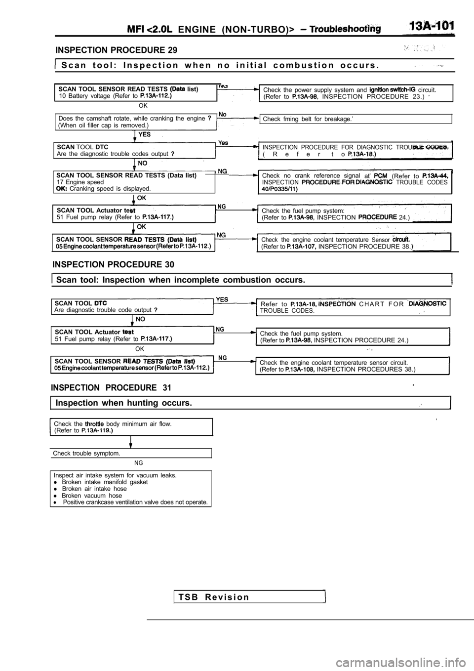
INSPECTION PROCEDURE 29
S c a n t o o l : I n s p e c t i o n w h e n n o i n i t i a l c o m b u s t i o n oc c u r s .
SCAN TOOL SENSOR READ TESTS
list)
10 Battery voltage (Refer to
OK
Check the power supply system and circuit.
(Refer to INSPECTION PROCEDURE 23.)
Does the camshaft rotate, while cranking the engine (When oil filler cap is removed.) Check fming belt for breakage.’
SCAN TOOLDTC
INSPECTION PROCEDURE FOR DIAGNOSTIC TROUBLE CODES.Are the diagnostic trouble codes output( R e f e r t o
SCAN TOOL SENSOR READ TESTS (Data list) Check no crank reference signal
at’(Refer to 17 Engine speedINSPECTION TROUBLE CODES Cranking speed is displayed.
SCAN TOOL Actuator teNGCheck the fuel pump system:51 Fuel pump relay (Refer to (Refer to INSPECTION 24.)
SCAN TOOL SENSOR
Check theengine coolant temperatureSensor(Refer to INSPECTION PROCEDURE 38.)
INSPECTION PROCEDURE 30
Scan tool: Inspection when incomplete combustion o ccurs.
SCAN TOOL
Refer to C H A R T F O R Are diagnostic trouble code outputTROUBLE CODES.
SCAN TOOL Actuator NG
51 Fuel pump relay (Refer to Check the fuel pump system. (Refer to INSPECTION PROCEDURE 24.)
OK ,
SCAN TOOL SENSOR NGCheck the engine coolant temperature sensor circuit .
(Refer to INSPECTION PROCEDURES 38.)
INSPECTION PROCEDURE 31.
Inspection when hunting occurs.
,
Check the body minimum air flow.
(Refer to
Check trouble symptom.
NG
Inspect air intake system for vacuum leaks.
l Broken intake manifold gasket
l Broken air intake hose
l Broken vacuum hose
lPositive crankcase ventilation valve does not opera te.
T S B R e v i s i o n
Page 518 of 2103
ENGINE
AND ENGINE> G e n e r a l
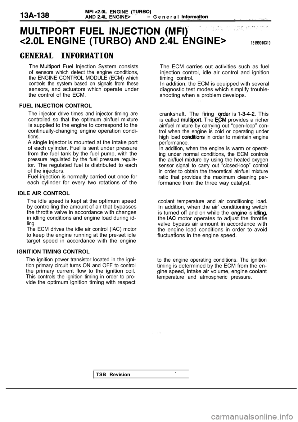
ENGINE (TURBO) AND ENGINE>13199910319
GENERAL INFORMATIONThe
Fuel Injection System consists
of sensors which detect the engine conditions,
the ENGINE CONTROL MODULE (ECM) which
controls the system based on signals from these
sensors, and actuators which operate under
the control of the ECM.
FUEL INJECTION CONTROL
The injector drive times and injector timing are
controlled so that the optimum air/fuel mixture
is supplied to the engine to correspond to the
continually-changing engine operation condi-
tions.
A single injector is mounted at the intake port
of each cylinder. Fuel is sent under pressure
from the fuel tank by the fuel pump, with the
pressure regulated by the fuel pressure regula-
tor. The regulated fuel is distributed to each
of the injectors.
Fuel injection is normally carried out once for
each cylinder for every two rotations of the
IDLE AIR CONTROL The idle speed is kept at the optimum speed
by controlling the amount of air that bypasses
the throttle valve in accordance with changes
in idling conditions and engine load during id-
ling.
The ECM drives the idle air control (IAC) motor
to keep the engine running at the pre-set idle
target speed in accordance with the engine
IGNITION TIMING CONTROL
The ignition power transistor located in the igni-
tion primary circuit turns ON and OFF to control
the primary current flow to the ignition coil.
This controls the ignition timing in order to pro-
vide the optimum ignition timing with respect The ECM carries out activities such as fuel
injection control, idle air control and ignition
timing control.
In addition, the ECM is equipped with several
diagnostic test modes which simplify trouble-
shooting when a problem develops.
. .
crankshaft. The firing is This
is called
The provides a richer
air/fuel mixture by carrying out “open-loop” con-
trol when the engine is cold or operating under high load
in order to maintain engine
performance. In addition, when the engine is warm or operat-
ing under normal conditions, the ECM controls
the air/fuel mixture by using the heated oxygen
sensor signal to carry out “closed-loop” control
in order to obtain the theoretical air/fuel mixture
ratio that provides the maximum cleaning per-
formance from the three way catalyst.
coolant temperature and air conditioning load.
In addition, when the air’ conditioning switch
is turned off and on while the
is
the motor operates to adjust the throttle
valve bypass air amount in accordance with
the engine load conditions in order to avoid
fluctuations in the engine speed.
to the engine operating conditions. The ignition
timing is determined by the ECM from the en-
gine speed, intake air volume, engine coolant
temperature and atmospheric pressure.
TSB Revision
Page 519 of 2103
ENGINE (TURBO)
ENGINE>
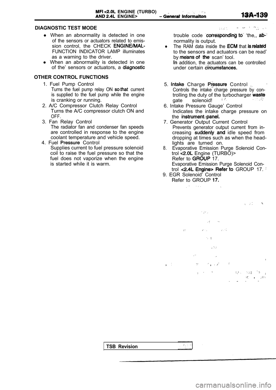
DIAGNOSTIC TEST MODEl When an abnormality is detected in one
of the sensors or actuators related to emis-
sion control, the CHECK
FUNCTION INDICATOR LAMP illuminates
as a warning to the driver.
l When an abnormality is detected in one
of the’ sensors or actuators, a
OTHER CONTROL FUNCTIONS
1. Fuel Pump Control
Turns the fuel pump relay ON current
is supplied to the fuel pump while the engine
is cranking or running.
2. A/C Compressor Clutch Relay Control Turns the A/C compressor clutch ON and
OFF.
3. Fan Relay Control
The radiator fan and condenser fan speeds
are controlled in response to the engine
coolant temperature and vehicle speed.
4. Fuel
Control
Supplies current to fuel pressure solenoid
coil to raise the fuel pressure so that the
fuel does not vaporize when the engine
is started while it is warm.
trouble code ‘the,,
normality is output.
lThe RAM data inside the that
to the sensors and actuators can be read’
by
scan’ tool.
addition, the actuators can be controlled
under certain
5. Charge Control
Controls the intake charge pressure by con-
trolling the duty of the turbocharger
gate solenoid!
6. Intake Pressure Gauge’ Control Indicates the intake charge pressure on
the
7. Generator Output Current Control
Prevents generator output current from in-
creasing idle speed from
dropping at times such as when the head-
lights are turned on.
8.Evaporative Emission Purge Solenoid Con-
trol Engine (TURBO)>
Refer to
17.
Evaporative Emission Purge Solenoid Con-
trol GROUP 17.
9. EGR Solenoid’ Control
Refer to GROUP
,,
,
TSB Revision
Page 523 of 2103
ENGINE (TURBO)
AND ENGINE> General lnformaiton
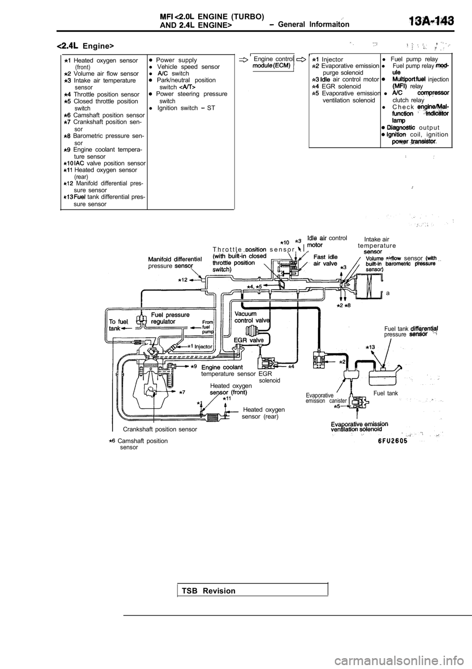
Engine>
Heated oxygen sensor Power supply(front)l Vehicle speed sensor Volume air flow sensor l switch Intake air temperature Park/neutral positionsensorswitch Throttle position sensor Power steering pressure Closed throttle positionswitch
switchl Ignition switch ST Camshaft position sensor Crankshaft position sen-sor Barometric pressure sen-sor Engine coolant tempera-
ture sensor
valve position sensor Heated oxygen sensor(rear) Manifold differential pres-sure sensor tank differential pres-
sure sensor
,
Engine control Injector l
Fuel pump relay Evaporative emission lFuel pump relay purge solenoid air control motor injection EGR solenoid relay Evaporative emission l ventilation solenoid clutch relay
l C h e c k
o u t p u t coil, ignition
T h r o t t l e s e n s o r ,
control
Intake air
t e m p e r a t u r e
. . . sensor pressure
a
temperature sensor EGR
solenoidHeated oxygen
Fuel tank pressure
sensor (rear) Heated oxygen
Evaporativeemission canisterFuel tank
Crankshaft position sensor
Camshaft positionsensor
TSB Revision
Page 524 of 2103
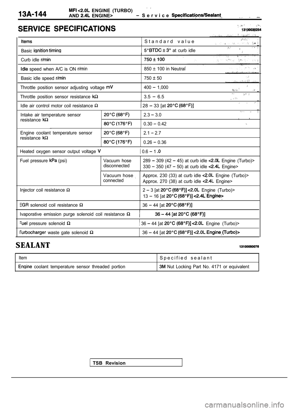
ENGINE (TURBO)
AND
ENGINE> S e r v i c e
S t a n d a r d v a l u e
Basic at curb idle ,
Curb idle
speed when A/C is ON 850 100 in Neutral
Basic idle speed
750 50
Throttle position sensor adjusting voltage
Throttle position sensor resistance
400 1,000
3.5 6.5
Idle air control motor coil resistance 28 33 [at
Intake air temperature sensor
resistance2.3 3.0,
0.30 0.42
Engine coolant temperature sensor
resistance2.1 2.7
0.26 0.36
Heated oxygen sensor output voltage
0.6 1
Fuel pressure (psi) Vacuum hose disconnected289 309 (42 45) at curb idle Engine (Turbo)>
330
350 (47 50) at curb idle Engine>
Injector coil resistance
solenoid coil resistance
Vacuum hose Approx. 230 (33) at curb idle Engine (Turbo)>
connected Approx. 270 (38) at curb idle
Engine>
2
3 [at Engine (Turbo)>
13
16 [at
36 44 [at
TSB Revision
Ivaporative emission purge solenoid coil resistance
pressure solenoid 36 44 [at Engine (Turbo)>
waste gate solenoid 36 44 [at
SEALANT
Item
coolant temperature sensor threaded portion
S p e c i f i e d s e a l a n t
Nut Locking Part No. 4171 or equivalent
Page 538 of 2103
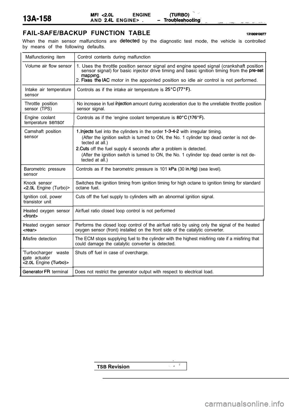
ENGINE
A N D E N G I N E > .
FAIL-SAFE/BACKUP FUNCTION TABLE
When the main sensor malfunctions are by the diagnostic test mode, the vehicle is controlled
by means of the following defaults.
Malfunctioning item Control contents during malfunct ion
Volume air flow sensor
1. Uses the throttle position sensor signal and eng ine speed signal (crankshaft position
sensor signal) for basic injector drive timing and basic ignition timing from the
2. motor in the appointed position so idle air contro l is not performed.
Intake air temperature
Controls as if the intake air temperature is
sensor
Throttle position
sensor (TPS)
Engine coolant
temperaturesensor
Camshaft position
sensor
Barometric pressure
sensor
Knock sensor
Engine (Turbo)>
Ignition coil, power
transistor unit
Heated oxygen sensor
Heated oxygen sensor
Misfire detection
Turbocharger waste
gate actuator Engine
terminal Performs the closed loop control of the air/fuel ra
tio by using only the signal of the heated
oxygen sensor (front) installed on the front side o f the catalytic converter.
The ECM stops supplying fuel to the cylinder with t he highest misfiring rate if a misfiring that
could damage the catalytic converter is detected.
Shuts off fuel in case of overcharge.
Does not restrict the generator output with respect to electrical load.
No increase in fuel amount during acceleration due to the unreliable throttle position
sensor signal.
Controls as if the ‘engine coolant temperature is
fuel into the cylinders in the order with irregular timing.
(After the ignition switch is turned to ON, the No. 1 cylinder top dead center is not de-
tected at all.)
off the fuel supply 4 seconds after a problem is d etected.
(After the ignition switch is turned to ON, the No. 1 cylinder top dead center is not de-
tected at all.)
Controls as if the barometric pressure is 101
(30 (sea level).
Switches the ignition timing from ignition timing f or high octane to ignition timing for standard
octane fuel.
Cuts off the fuel supply to cylinders with an abnor mal ignition signal.
Air/fuel ratio closed loop control is not performed
TSB Revision
Page 554 of 2103
![MITSUBISHI SPYDER 1990 Service Owners Guide E N G I N E ( T U R B O ) .
AND ENGINE> ,
Code No. Random Misfire Detected
[Comment]l Ignition system related part(s) BackgroundlIf a misfiring occurs while the engine is runni](/img/19/57345/w960_57345-553.png "MITSUBISHI SPYDER 1990 Service Owners Guide E N G I N E ( T U R B O ) .
AND ENGINE> ,
Code No. Random Misfire Detected
[Comment]l Ignition system related part(s) BackgroundlIf a misfiring occurs while the engine is runni")
E N G I N E ( T U R B O ) .
AND ENGINE> ,
Code No. Random Misfire Detected
[Comment]l Ignition system related part(s) BackgroundlIf a misfiring occurs while the engine is running, the engine speed suddenly changes.l
Poor crankshaft sensor l Incorrect air/fuel ratiol The engine control module checks for changes in the engine speed.
l Low compression
Check ArealEngine coolant sensor: l 5 or more have passed after the engine was started. l
liming belt broken
l Engine speed is at between 500 and 6000 l Injector failedl Engine coolant temperature is or higher, l
EGR valve failed
l Intake air temperature is or higherlEngine control l Barometric pressure is 76 (11 psi.) or higher.l Running free from sudden accelerations/deceleration s such as shift change.
Judgement Criteria. .
(change in the angular acceleration of the crankshaft is used for misfire detection.)lMisfire has occurred more frequently than allowed during the last 200 revolutions [when
the catalyst temperature is higher than
orlMisfire has occurred in 20 or more of the last 1000 revolutions (corresponding to 1.5
times the limit of emission standard.) I,
SCAN TOOL Data list
22 Crankshaft position sensor (Refer to
l Crankshaft position sensor wave form check
l Engine speed: stable
OK: Constant pulse range
OK
position sensor and
Check the injector (Refer toNG Replace
Check the fuel trim malfunction (bank 1) (Refer to IN-SPECTION PROCEDURE FOR DIAGNOSTIC TROUBLE
OK
SCAN TOOL list
21 Engine coolant temperature sensor (Refer to
OK
Check the engine coolant temperature circuit malfu nction (Refer
to INSPECTION PROCEDURE FOR DIAGNOSTICTROUBLE CODE 5.)
Check the following items.
l Check the ignition coil, spark plugs, spark plug ca bles.
l Check the compression pressure.
l Check for broken timing belt teeth.
l Check the EGR system and the EGR valve.
TSB Revision