oil temperature MITSUBISHI SPYDER 1990 Service Owner's Manual
[x] Cancel search | Manufacturer: MITSUBISHI, Model Year: 1990, Model line: SPYDER, Model: MITSUBISHI SPYDER 1990Pages: 2103, PDF Size: 68.98 MB
Page 280 of 2103
ENGINEOn-vehicle
5. Cover the spark plug hole with a shop towel etc., and
after the engine has been cranked, check that no foreign
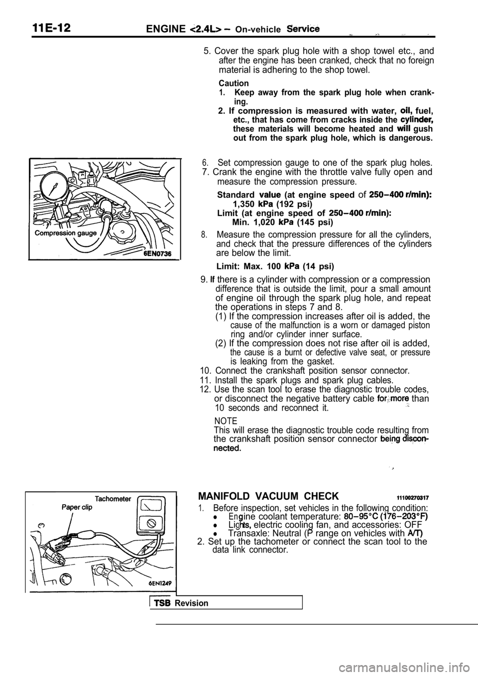
material is adhering to the shop towel.
Caution
1.Keep away from the spark plug hole when crank-
ing.
2. If compression is measured with water, fuel,
etc., that has come from cracks inside the
these materials will become heated and gush
out from the spark plug hole, which is dangerous.
6.Set compression gauge to one of the spark plug hole s.
7. Crank the engine with the throttle valve fully open and
measure the compression pressure.
Standard (at engine speed of
1,350 (192 psi)
Limit (at engine speed of
Min. 1,020 (145 psi)
8.Measure the compression pressure for all the cylind ers,
and check that the pressure differences of the cyli nders
are below the limit.
Limit: Max. 100 (14 psi)
9. there is a cylinder with compression or a compression
difference that is outside the limit, pour a small amount
of engine oil through the spark plug hole, and repe at
the operations in steps 7 and 8.
(1) If the compression increases after oil is added , the
cause of the malfunction is a worn or damaged pisto n
ring and/or cylinder inner surface.
(2) If the compression does not rise after oil is added,
the cause is a burnt or defective valve seat, or pr essure
is leaking from the gasket.
10. Connect the crankshaft position sensor connecto r.
11. Install the spark plugs and spark plug cables.
12. Use the scan tool to erase the diagnostic troub le codes,
or disconnect the negative battery cable than
10 seconds and reconnect it.
NOTE
This will erase the diagnostic trouble code resulting from
the crankshaft position sensor connector
MANIFOLD VACUUM CHECK
1.Before inspection, set vehicles in the following co ndition:
lEn
lLig electric cooling fan, and accessories: OFF
ine coolant temperature:
lTransaxle: Neutral (P range on vehicles with
2. Set up the tachometer or connect the scan tool t o the
data link connector.
Revision
Page 284 of 2103
.
4 . 9 N m
\ / X L - -3.6
. .
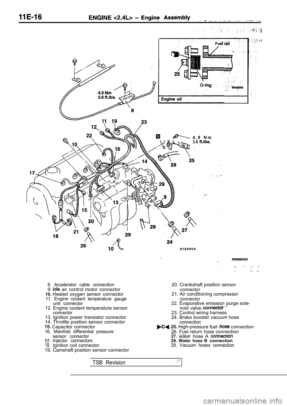
8. Accelerator cable connection9. air control motor connector
10. Heated oxygen sensor connector
11. Engine coolant temperature gauge
unit connector
12. Engine coolant temperature sensorconnector13. Ignition power transistor connector
14. Throttle position sensor connector
Capacitor connector16. Manifold differential pressure
20. Crankshaft position sensor
connector21. Air conditioning compressor
connector22. Evaporative emission purge sole-
noid valve
23. Control wiring harness
24. Brake booster vacuum hose
connection High-pressure fuel connection
26. Fuel return hose connection --
. .. .
17.18.
sensor connector
Injector connectors
Ignition coil connector
19. Camshaft position sensor connector 27.
water nose A 28. Water hose connection29. Vacuum hoses connection
TSB Revision
Page 336 of 2103
ENGINE OVERHAUL intake Manifold
sealant
3 mm
bead sealant
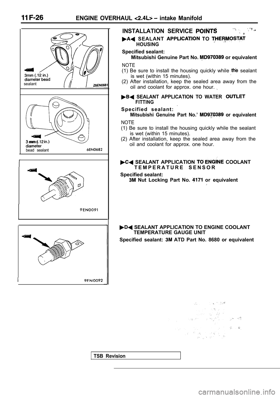
INSTALLATION SERVICE ,
S E A L A N T TO
HOUSING
Specified sealant:Mitsubishi Genuine Part No.
or equivalent
NOTE
(1) Be sure to install the housing quickly while sealant
is wet (within 15 minutes).
(2) After installation, keep the sealed area away f rom the
oil and coolant for approx. one hour.
SEALANT APPLICATION TO WATER
FITTING
S p e c i f i e d s e a l a n t :
Mitsubishi Genuine Part No.’ or equivalent
NOTE
(1) Be sure to install the housing quickly while th e sealant
is wet (within 15 minutes).
(2) After installation, keep the sealed area away f rom the
oil and coolant for approx. one hour.
SEALANT APPLICATION COOLANT
T E M P E R A T U R E S E N S O R
Specified sealant:
Nut Locking Part No. or equivalent
SEALANT APPLICATION TO ENGINE COOLANT TEMPERATURE GAUGE UNIT
Specified sealant:
ATD Part No. 8680 or equivalent
TSB Revision
Page 376 of 2103
![MITSUBISHI SPYDER 1990 Service Owners Manual 12-4 L U B R I C A T I O N
EngineI
Turbo
4. Supply new engine oil through the oil filler.Engine oil total quantity:[including oil filter and oil cooler]
Engine (Non-turbo) arid](/img/19/57345/w960_57345-375.png "MITSUBISHI SPYDER 1990 Service Owners Manual 12-4 L U B R I C A T I O N
EngineI
Turbo
4. Supply new engine oil through the oil filler.Engine oil total quantity:[including oil filter and oil cooler]
Engine (Non-turbo) arid")
12-4 L U B R I C A T I O N
EngineI
Turbo
4. Supply new engine oil through the oil filler.Engine oil total quantity:[including oil filter and oil cooler]
Engine (Non-turbo) arid
4 . 3 (4 q t s . )
Engine (Turbo)>
4.4
(4.6 qts.)
5. Start and run the engine a
minutes.
6.Stop the engine and check the engine oil level is w ithin
the level range indicated on the oil dipstick.
.
NOTE
may be used for operation in very cold weather
areas where the lowest ambient temperature is below
OIL REPLACEMENT
1. Remove the engine oil filler cap.
2.Remove the engine oil drain plug, and drain out the engine
o i l .
3.Remove the engine oil filter by using the oil filter wrench.
4.Clean the oil filter mounting, surface of the oil f ilter bracket.
5. Coat engine oil to the O-ring of’new filter: .
6.Screw on the oil filter by hand until it touchesthe surface
of the flange and then tighten it with. the filter wrench:
etc.
Engine (Turbo) Engine>
lFor One full turn or 14 Nm
lFor or 17 Nm (12
E n g i n e ( N o n - t u r b o ) >
lFor 090: turn or 21 Nm (15
7. Add new engine oil through the oil filter.
8. Start and run engine and check for engine oil le aks.
9. After stopping engine, check oil level and reple nish as
necessary.
TSB Revision
Page 383 of 2103
ENGINE (NON-TURBO)> General
FUEL INJECTION
ENGINE (NON-TURBO)>
GENERAL INFORMATION
The Fuel Injection System consists
of sensors which detect the engine conditions,
the POWERTRAIN CONTROL MODULE(PCM) which controls the system based on
signals from these sensors, and actuators
which operate under the control of the PCM.
FUEL INJECTION CONTROL
The injector drive times and injector timing are
controlled so that the optimum air/fuel mixture
is supplied to the engine to correspond to the
continually-changing engine operation condi-
tions.
A single injector is mounted at the intake port
of each cylinder. Fuel is sent under pressure
from the fuel tank by the fuel pump, with the
pressure regulated by the fuel pressureregulator. The regulated fuel is distributed
to each of the injectors. Fuel injection is normally carried out once for
each cylinder for every two rotations of the
crankshaft. The firing order is
This
IDLE AIR CONTROL The idle speed’ is kept at the optimum speed
by controlling the amount of air that bypasses
the throttle valve in accordance with changes in idling conditions and engine load during
idling.
The PCM drives the idle air control (IAC) motor
to keep the engine running at the idle
target speed in accordance with the engine
IGNITION TIMING CONTROL
The ignition power transistor is built into the
PCM. It turns the ignition primary circuit on
and off to respectively supply and cut off primary
current flow to the ignition coil. The PCM carries
activities such fuel
injection control, idle air control and ignition
timing control.
In addition, the
diagnostict e s twhich simplify
troubleshooting when a problem develops.
is called The PCM
air/fuel mixture by carrying out “open-loop”
control when the engine is cold or operating
under high load conditions in to maintain
engine performance.
In addition, when the engine warm or
operating under normal
the PCM
controls the air/fuel mixture by using the heated
oxygen sensor signal to carry out “closed-loop”
control in order to obtain the theoretical air/fuel
mixture ratio that provides the maximum
cleaning
from the three way
catalyst.
coolant temperature and air conditioning load.
In addition, when the air conditioning switch
is turned off and on while the engine is idling,
the
motor operates to adjust the throttle
valve bypass air amount in accordance with
the engine load conditions in order to avoid
fluctuations in the engine speed.
This controls the ignition timing in order to
provide the optimum ignition timing with respect
to the engine operating conditions. The ignition
timing is determined by the PCM from the
engine speed, intake air volume, engine coolant
temperature and atmospheric pressure.
TSB Revision
Page 386 of 2103
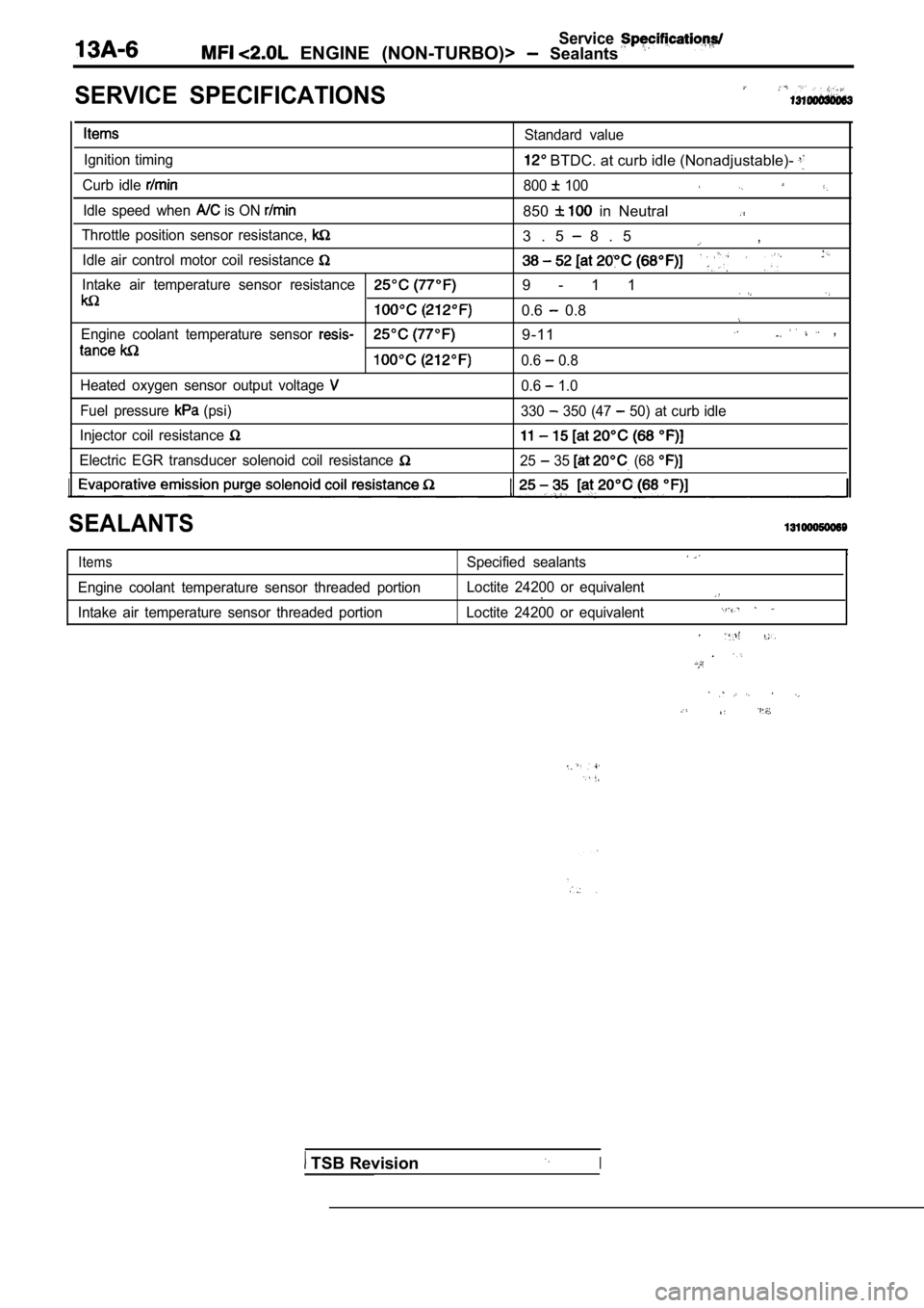
Service ENGINE (NON-TURBO)> Sealants
SERVICE SPECIFICATIONS
Ignition timing
Curb idle
Idle speed when is ON
Standard value
BTDC. at curb idle (Nonadjustable)-
800 100
850 in Neutral
Throttle position sensor resistance,
Idle air control motor coil resistance
Intake air temperature sensor resistance
Engine coolant temperature sensor
Heated oxygen sensor output voltage
Fuel pressure (psi)
Injector coil resistance
Electric EGR transducer solenoid coil resistance
3 . 5 8 . 5 ,
9 - 1 1
0.6 0.8
9-11 ,
0.6 0.8
0.6
1.0
330
350 (47 50) at curb idle
25 35 (68
SEALANTS
Items
Engine coolant temperature sensor threaded portion
Intake air temperature sensor threaded portion
,Specified sealants
Loctite 24200 or equivalent.
Loctite 24200 or equivalent
.
TSB RevisionI
Page 389 of 2103
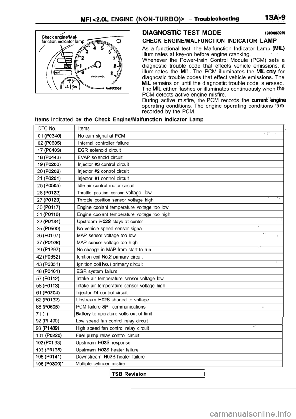
ENGINE (NON-TURBO)>
TEST MODE
CHECK ENGINE/MALFUNCTION INDICATOR LAMP
As a functional test, the Malfunction Indicator Lam p
illuminates at key-on before engine cranking.
Whenever the Power-train Control Module (PCM) sets a
diagnostic trouble code that effects vehicle emissi ons, it
illuminates the
The PCM illuminates the for
diagnostic trouble codes that effect vehicle emissi ons. The
remains on until the diagnostic trouble code is erased.
The
either flashes or illuminates continuously when
PCM detects active engine misfire.
During active misfire, thePCM records the
operating conditions. The engine operating conditio ns
recorded by the PCM.
ItemsIndicated by the Check Engine/Malfunction Indicator Lamp
DTC No. Items
01No cam signal at PCM
02Internal controller failure
EGR solenoid circuit
EVAP solenoid circuit
Injector control circuit
20Injector control circuit
21Injector control circuit
25Idle air control motor circuit
26Throttle position sensor voltage low
27Throttle position sensor voltage high
30Engine coolant temperature voltage too low
31Engine coolant temperature voltage too high
32Upstream stays at center
35
No vehicle speed sensor signal
36
07) MAP sensor voltage too low
37MAP sensor voltage too high
39No change in MAP from start to run
42Ignition coil primary circuit
43Ignition coil primary circuit
46
EGR system failure
57Intake air temperature sensor voltage low
58Intake air temperature sensor voltage high
61Injector control circuit
62Upstream shorted to voltage
68PCM failure communications
71 temperature volts out of limit
, .
,
92 (PI 490)
93
101
33)
103
Low speed fan control relay circuit
High speed fan control relay circuit
Fuel pump relay control circuit
Upstream
response
Upstream
heater failure
Downstream
heater failure
Multiple cylinder misfire
TSB RevisionI
Page 399 of 2103
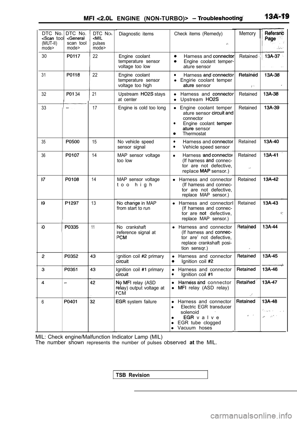
ENGINE (NON-TURBO)>
1MemoryDiagnostic itemsCheck items (Remedy)
Engine coolantHarness and
temperature sensorEngine coolant temper
voltage too low
ature sensor
Engine coolantlHarness
temperature sensorl Engirie coolant temper
voltage too high sensor
Upstream staysl Harness and
at centerl Upstream
Engine is cold too longl Engine coolant temper
ature sensor
connectorlEngine coolant
sensor
Thermostat
No vehicle speed
lHarness and
sensor signallVehicle speed sensor
MAP sensor voltagelHarness
too low (If harness connec-
tor are not defective, replace
sensor.)
MAP sensor voltagel Harness and connector
t o o h i g h
(If harness and connec-
tor are not defective,
replace MAP sensor.)
No
in MAPl Harness and connector
from start to run (If harness and connec-
tor are defective,
replace MAP sensor.)
No crankshaftl Harness and connector
reference signal at (If harness and
tor are’ not defective,
replace crankshaft posi-
tion sensqr.)
gnition coil
primaryl Harness and connector
Ignition coil
gnition coil primaryl Harness and connectorlIgnition coil
relay (ASDl connector
ay) output voltage atl relay (ASD relay)
‘CM
system failurel Harness and connector
lElectric EGR transducer
solenoid
l v a l v e
l EGR tube clogged
l Vacuum hoses
DTC NC
pulses
mode>
DTC No. DTC No. tool (MUT-II)scan toolmode>mode>
30
31
32 34
1
I
I
I
I
Retained22
22
,
I
I
I
Retained
Retained
21
17
15
14
14
33
35Retained
36Retained
Retained
13Retained
11
6
MIL: Check engine/Malfunction Indicator Lamp (MIL)
The number shown represents the number of pulses observedatthe MIL.
TSB Revision
Page 434 of 2103
![MITSUBISHI SPYDER 1990 Service Owners Manual ENGINE
Scan tool 92
C o d e G e n e r a l s c a n t o o l L o w S p e e d F a n
No.Circuit, 35,
[Comment]l Relay coil open or shortedBackgroundlThe low speed radiator fan re](/img/19/57345/w960_57345-433.png "MITSUBISHI SPYDER 1990 Service Owners Manual ENGINE
Scan tool 92
C o d e G e n e r a l s c a n t o o l L o w S p e e d F a n
No.Circuit, 35,
[Comment]l Relay coil open or shortedBackgroundlThe low speed radiator fan re")
ENGINE
Scan tool 92
C o d e G e n e r a l s c a n t o o l L o w S p e e d F a n
No.Circuit, 35,
[Comment]l Relay coil open or shortedBackgroundlThe low speed radiator fan relay controls the low of the radiator fan. l
Ignition switch output circuit openOne side of the relay control coil is supplied with 12 volts when the ignition switch isl
Low speed radiator fan l o r turned to the ON position.
l The circuit is completed when the other side of the relay coil is grounded by the PCM.l .
lThe PCM grounds the relay control circuit depending
on engine coolant temperature etc. . . Range of Checkl
Battery voltage: 10 or morel Ignition switch: ONSet ConditionlAn open or short-circuit condition is detected in t he low speed radiator fan relay controlcircuit for 3 seconds.
NGMeasure at the PCM connector Check the radiator fan relay drcuit.lDisconnect the connector, and measure at the harnes s side.
l Voltage between 55 and ground
(ignition switch: ON)
OK: Battery positive voltage
l Connect a jumper wire between 55 and ground.
(Ignition switch: ON)
OKRadiator fan runs at low speed.
OKNG Repair
OK
Check trouble symptom.
Replace the PCM.
NG
TSB Revision
Page 435 of 2103
![MITSUBISHI SPYDER 1990 Service Owners Manual ENGINE
Scan tool 93
Code General scan tool High Speed Fan
No.Control Relay Circuit
35
[Comment]
Background
lThe high speed condenser fan relay controls the hig h speed operation of the](/img/19/57345/w960_57345-434.png "MITSUBISHI SPYDER 1990 Service Owners Manual ENGINE
Scan tool 93
Code General scan tool High Speed Fan
No.Control Relay Circuit
35
[Comment]
Background
lThe high speed condenser fan relay controls the hig h speed operation of the")
ENGINE
Scan tool 93
Code General scan tool High Speed Fan
No.Control Relay Circuit
35
[Comment]
Background
lThe high speed condenser fan relay controls the hig h speed operation of the condenserfan.lOne side of the relay control coil is supplied with 12 volts when the ignition switch is
turned to the ON position.
lThe circuit is completed when the other side of the relay coil is grounded by the PCM.lThe PCM grounds the relay control circuit depending on engine coolant temperature and
other conditions.
Range of Check
l Battery voltage:
or more Ignition switch: ONSet ConditionAn open or shorted condition is detected in the hig h speed condenser fan relay controlcircuit for 3 seconds.
lRelay, coil open, shorted . ..
lHigh speed condenser fan relay control circuito p e n PCM failed
Measure at the PCM connector lDisconnect the connector, and measure at the harnes s side.Check the condenser fan circuit.
l Voltage between 19 and ground
(Ignition switch: ON)
OK: Battery positive voltage
l Connect a jumper wire between 19 and ground.
(Ignition switch: ON)
OK A/C condenser fan runs at high speed.
OK. . . . NG RepairCheck the following connector: IOK
Check trouble symptom.
Replace the PCM.
TSB Revision