oil temperature MITSUBISHI SPYDER 1990 Service User Guide
[x] Cancel search | Manufacturer: MITSUBISHI, Model Year: 1990, Model line: SPYDER, Model: MITSUBISHI SPYDER 1990Pages: 2103, PDF Size: 68.98 MB
Page 108 of 2103
![MITSUBISHI SPYDER 1990 Service User Guide ENGINE OVERHAUL
Items Standard value
Piston ring end gap mm (in.)
Piston pin O.D. mm (in.)
0 . 8
Oil 9 . 8
21
Piston pin press-in load (Ibs.)
[Room temperature]
Crankshaft pin](/img/19/57345/w960_57345-107.png "MITSUBISHI SPYDER 1990 Service User Guide ENGINE OVERHAUL
Items Standard value
Piston ring end gap mm (in.)
Piston pin O.D. mm (in.)
0 . 8
Oil 9 . 8
21
Piston pin press-in load (Ibs.)
[Room temperature]
Crankshaft pin")
ENGINE OVERHAUL
Items Standard value
Piston ring end gap mm (in.)
Piston pin O.D. mm (in.)
0 . 8
Oil 9 . 8
21
Piston pin press-in load (Ibs.)
[Room temperature]
Crankshaft pin oil clearance mm (in.) 17,500
Connecting rod big end side clearance mm (in.)
Crankshaft, flywheel and drive plate
Bearing cap bolt shank length mm (in.)
0 . 4
Crankshaft end play mm (in.)
Crankshaft journal O.D. mm (in.) 0 . 2 5
57 (2.24)
pin O.D. mm (in.) 42 (1.77)
Crankshaft journal oil clearance mm (in.)
to cylinder clearance mm (in.)
0 . 1
block flatness of gasket surface mm (in.) 0.05 0.1
block grinding limit of gasket surface mm (in.)l 0.2‘Total resurfacing depth of both cylinder head and cylinder block
block overall height mm (in.)283.9-284.1
(11.177-11.185)
block I.D. mm (in.) 85.0 (3.35)
TSBRevision
REWORK DIMENSIONS
Items
Cylinder head and valve
Oversize rework dimensions of valve guide0.05 O.S.
hole (both intake and exhaust) mm (in.) 0.25 O.S.
0.50
Intake oversize rework 0.3
dimensions of valve seat hole mm (in.)
0.6 O.S.
Exhaust oversize rework dimensions of valve 0.3 O.S.
seat hole
mm (in.)0.6 O.S.
Crankshaft, flywheel and drive plate
Crankshaft out of roundness and taper of journal an d pin mm (in.)
Standard value
12.25-12.27 ,
,
Max. 0.01
NOTE
O.D.: Outer diameter
I.D.: Inner diameter
Oversize diameter
Page 109 of 2103

ENGINE OVERHAUL
TORQUE SPECIFICATIONS
, ,
I
I I
I
I I
I
I
I I
Items
Generator and ignition system
W a t e r p u l l e y b o l tpump
Generator mounting bolt
Generator brace bolt
Generator pivot nut
Crankshaft pulley bolt
Spark plug
Ignition coil bolt
Center cover bolt Ignition power transistor bolt
Plate
Camshaft position sensor
Camshaft position sensor support
Camshaft position sensing cylinder
Timing belt
Crankshaft position sensor bolt
Tensioner pulley bolt
Tensioner arm bolt
Auto tensioner bolt Idler pulley bolt
Oil sprocket nutpump
Crankshaft bolt
Tensioner
bolt
Counterbalance shaft sprocket bolt
Camshaft sprocket bolt
Engine support bracket bolt
Fuel and emission parts
EGR valve bolt
Throttle body stay bolt
Throttle body bolt
Fuel pressure regulator bolt
Intake manifold
manifold bolt
ntake manifold nut ntake manifold stay bolt
ntake manifold plenum bolt and nut
ntake manifold plenum stay bolt
outlet fitting bolt
coolant temperature gauge unit
coolant temperature sensor
TSB Revision
N m
118”
23 17
2417
1410
25 18
25 18
1410
32
1410
107
97
14 10
2216
97
4935
22 16
24
‘17’
3827
5540
12087
1914
4633
9065
45 33
22 16
19 14
1914
97
2014
3626
2820
18
1813
1914
118
30 22
Page 111 of 2103
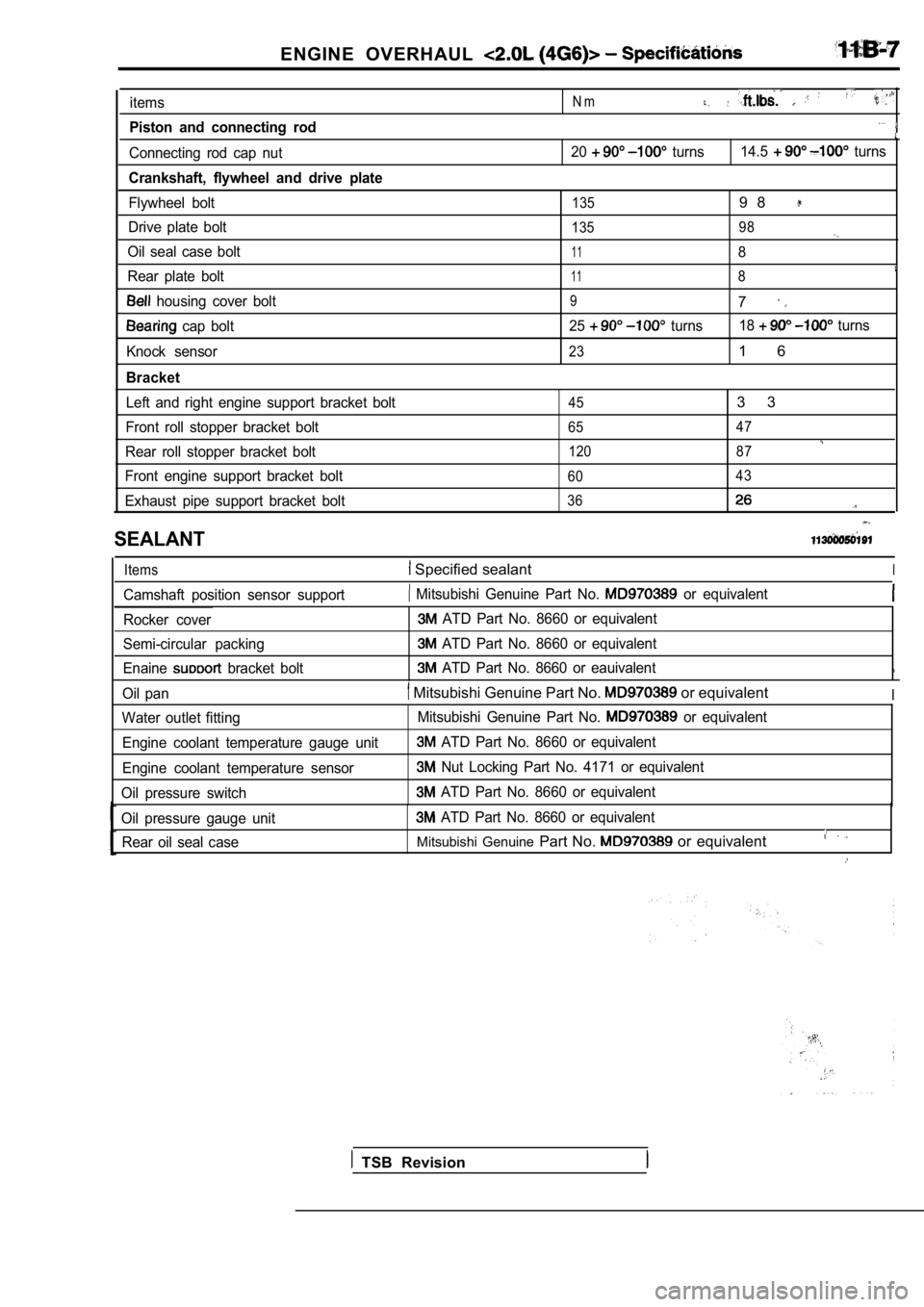
ENGINE OVERHAUL
items
Piston and connecting rod
Connecting rod cap nut
Crankshaft, flywheel and drive plate
Flywheel bolt
Drive plate bolt
Oil seal case bolt
Rear plate bolt
housing cover bolt
cap bolt
Knock sensor
Bracket
Left and right engine support bracket bolt
Front roll stopper bracket bolt
Rear roll stopper bracket bolt
Front engine support bracket bolt
Exhaust pipe support bracket bolt
N m
20 turns 14.5 turns
1359 8
135 98
118
118
97
25 turns18 turns
231 6
453 3
65 47
120 87
60 43
36
SEALANT
Items Specified sealantI
Camshaft position sensor support Mitsubishi Genuine Part No. or equivalent
Rocker cover
Semi-circular packing
Enaine
bracket bolt
ATD Part No. 8660 or equivalent
ATD Part No. 8660 or equivalent
ATD Part No. 8660 or eauivalent
Oil pan Mitsubishi Genuine Part No. or equivalentI
Water outlet fitting
Engine coolant temperature gauge unit
Engine coolant temperature sensor
Oil pressure switch Mitsubishi Genuine Part No. or equivalent
ATD Part No. 8660 or equivalent
Nut Locking Part No. 4171 or equivalent
ATD Part No. 8660 or equivalent
Oil pressure gauge unit
ATD Part No. 8660 or equivalent
Rear oil seal case
Mitsubishi Genuine Part No. or equivalent
TSB Revision
Page 131 of 2103
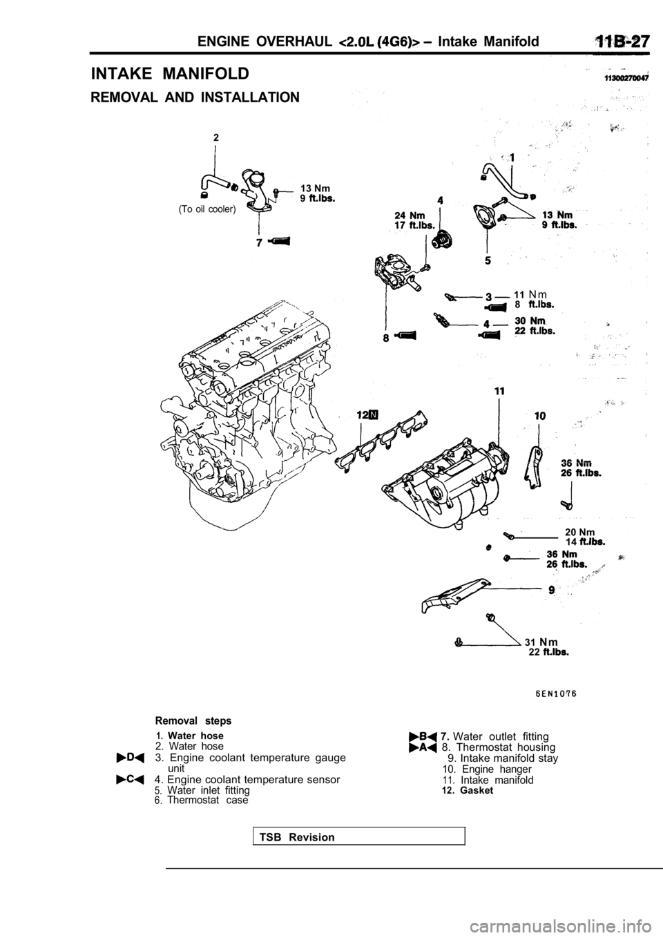
ENGINE OVERHAUL Intake Manifold
INTAKE MANIFOLD
REMOVAL AND INSTALLATION
2
(To oil cooler)
13 Nm
9
11 N m 8
20 Nm
14
31 N m
22
Removal steps
1.Water hose2. Water hose
3. Engine coolant temperature gaugeunit
4. Engine coolant temperature sensor5.Water inlet fitting6.Thermostat case
7. Water outlet fitting 8. Thermostat housing
9. Intake manifold stay
10. Engine hanger11.Intake manifold12.Gasket
TSB Revision
Page 132 of 2103
11ENGINE OVERHAUL
in.)diameterbead
diameter
bead sealant
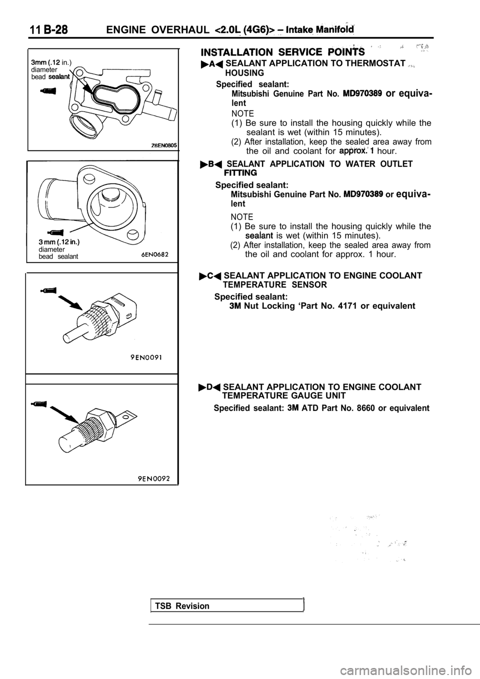
SEALANT APPLICATION TO THERMOSTAT
HOUSING
Specified sealant:
Mitsubishi Genuine Part No. or equiva-
lent
NOTE
(1) Be sure to install the housing quickly while th e
sealant is wet (within 15 minutes).
(2) After installation, keep the sealed area away f rom
the oil and coolant for hour.
SEALANT APPLICATION TO WATER OUTLET
Specified sealant:
Mitsubishi Genuine Part No. or equiva-
lent
NOTE
(1) Be sure to install the housing quickly while the
is wet (within 15 minutes).
(2) After installation, keep the sealed area away f rom
the oil and coolant for approx. 1 hour.
SEALANT APPLICATION TO ENGINE COOLANT
TEMPERATURE SENSOR
Specified sealant:
Nut Locking ‘Part No. 4171 or equivalent
SEALANT APPLICATION TO ENGINE COOLANT
TEMPERATURE GAUGE UNIT
Specified sealant: ATD Part No. 8660 or equivalent
TSB Revision
Page 180 of 2103
ENGINE On-vehicle Service
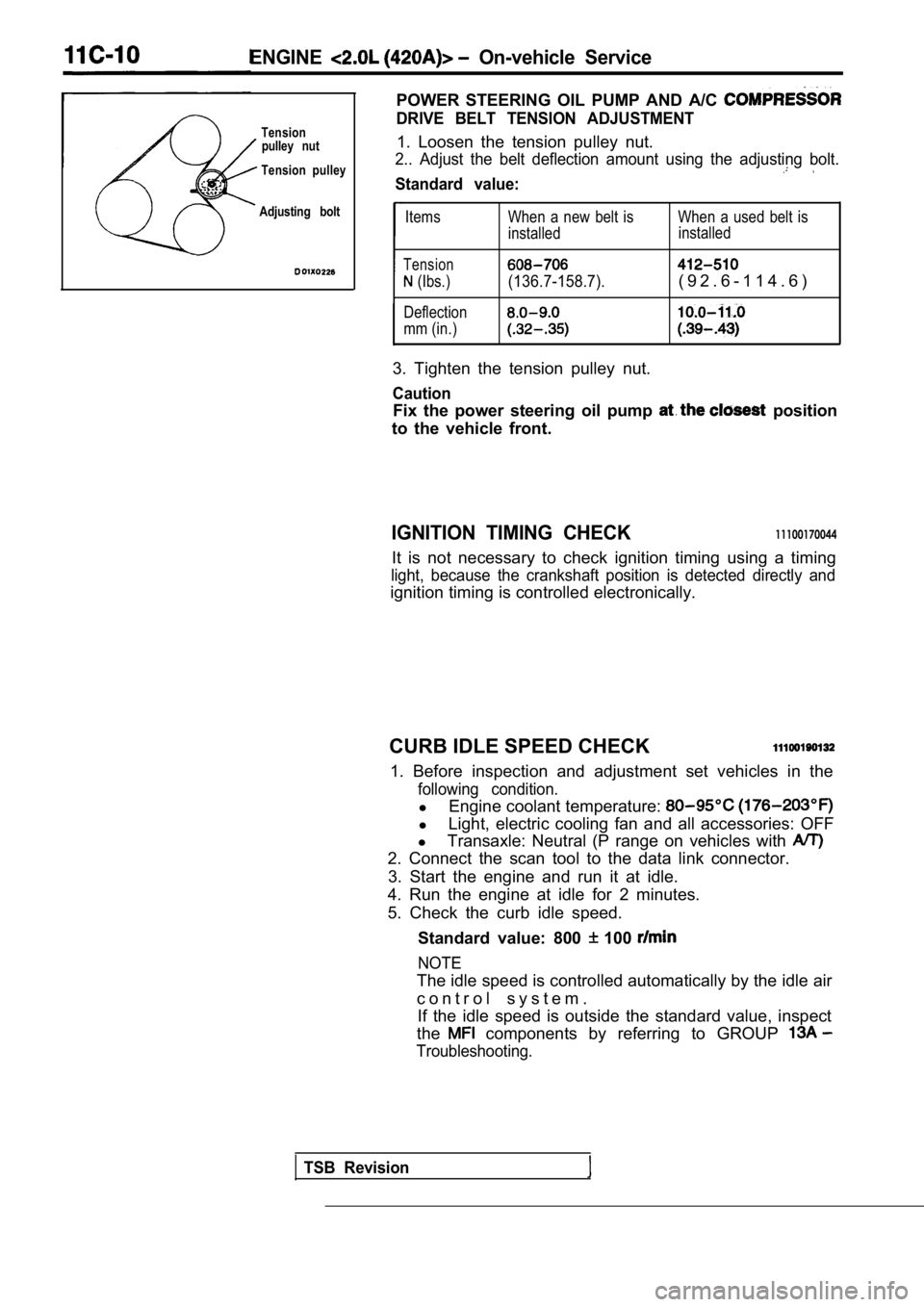
POWER STEERING OIL PUMP AND A/C
DRIVE BELT TENSION ADJUSTMENTTensionpulley nut1. Loosen the tension pulley nut.
Tension pulley2.. Adjust the belt deflection amount using the adj usting bolt.
Standard value:
Adjusting boltItems
Tension
(Ibs.)
Deflection
mm (in.) When a new belt is When a used belt is
installed
installed(136.7-158.7).( 9 2 . 6 - 1 1 4 . 6 )
3. Tighten the tension pulley nut.
Caution
Fix the power steering oil pump position
to the vehicle front.
IGNITION TIMING CHECK11100170044
It is not necessary to check ignition timing using a timing
light, because the crankshaft position is detected directly and
ignition timing is controlled electronically.
CURB IDLE SPEED CHECK
1. Before inspection and adjustment set vehicles in the
following condition.
lEngine coolant temperature:
lLight, electric cooling fan and all accessories: OF F
l Transaxle: Neutral (P range on vehicles with
2. Connect the scan tool to the data link connector .
3. Start the engine and run it at idle.
4. Run the engine at idle for 2 minutes.
5. Check the curb idle speed.
Standard value: 800
100
NOTE
The idle speed is controlled automatically by the i dle air
c o n t r o l s y s t e m . If the idle speed is outside the standard value, in spect
the
components by referring to GROUP
Troubleshooting.
TSB Revision
Page 181 of 2103
ENGINE On-vehicle Service
IDLE MIXTURE CHECK
11100210081
1.Before inspection, set vehicles in the following co ndition:
lEngine coolant temperature:
l Lights, electric cooling fan and all accessories: O FF
lTransaxle: Neutral (P range on vehicles with
2.After turning the ignition switch to OFF, connect t he scan
tool to the data link connector.
3.Start the engine and run it at 2,500 for 2 minutes.
4. Set the CO, HC tester.
5. Check the CO contents and the HC contents at idl e.
Standard value:
CO contents: 0.5% or less
HC contents: 100 ppm or less
6. If the idle speed is outside the standard value, check
the following items: l Diagnostic output
l Closed-loop control (When the closed-loop control
is carried out normally, the output signal of the h eated
oxygen sensor repeats between and
,000 at idle.)
l Fuel pressure
I n j e c t o r
lIgnition coil, spark plug cable, spark plug
lEGR system and the EGR valve leak
l Evaporative emission control system
Compression pressure
NOTE
Replace the three-way catalyst whenever the CO and
HC contents do not remain inside the standard value .
(even though the result of the inspection is normal on
all items.)
COMPRESSION PRESSURE CHECK
1.Before inspection, check that the engine oil, start er and
battery are normal. Also, set the vehicle to the fo llowing
condition:
lEngine coolant temperature:
lLights, electric cooling fan and all accessories: O FF
lTransaxle: Neutral (P range on vehicle with
2. Disconnect the spark plug cables.
3. Remove all spark plugs.
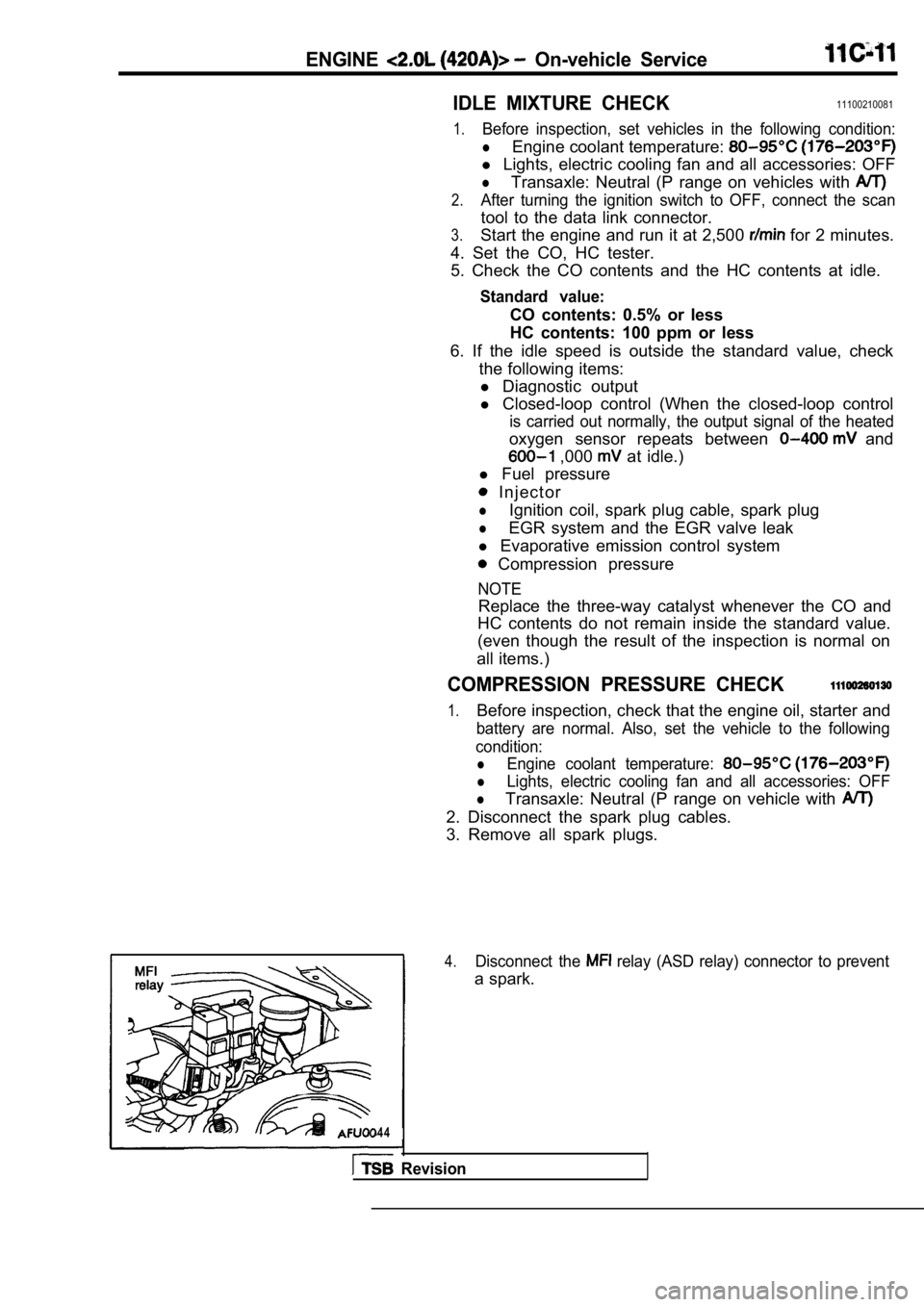
4.Disconnect the relay (ASD relay) connector to prevent
a spark.
4 4
Revision
Page 199 of 2103
Cylinder Head
CYLINDER HEAD GASKET
REMOVAL AND INSTALLATION
Operation
lFuel Line Pressure Releasing (Refer to GROUP On-vehicle Service.)l Engine Coolant Draining(Refer to GROUP 00 Maintenance Service.)l Engine Oil Draining(Refer to GROUP 00 Maintenance Service.)l Air Cleaner Removal
6
Post-installation Operationl Air Cleaner Installationl Engine Oil (Refer to GROU00 Maintenance Service.)l Engine Coolant Supplying(Refer to GROUP 00 Maintenance Service.)lAccelerator Cable Adjustment (Refer to GROUP
17 On-vehicle Service.)
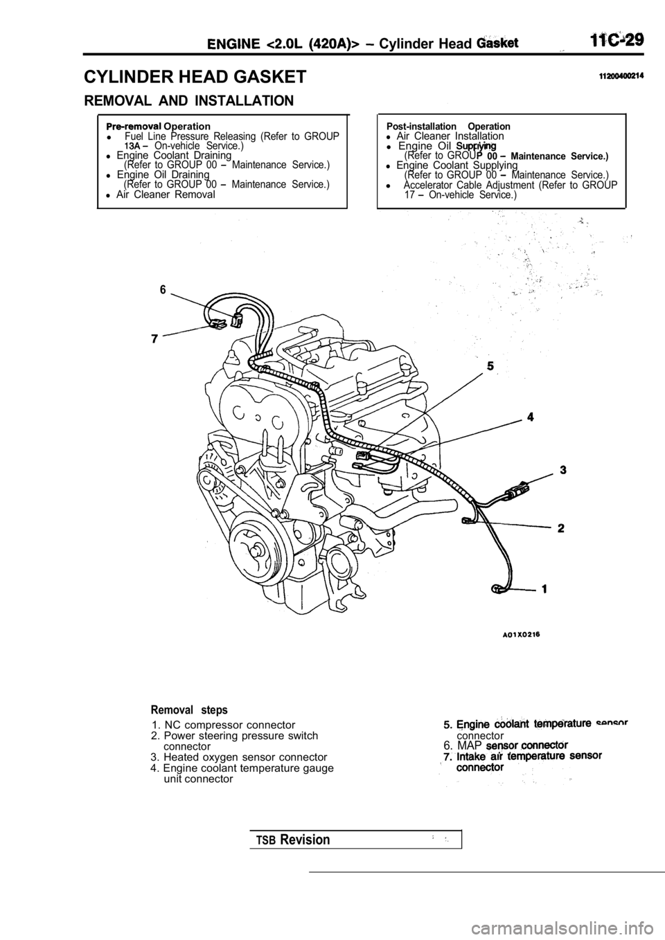
Removal steps
1. NC compressor connector
2. Power steering pressure switch
connector3. Heated oxygen sensor connector
4. Engine coolant temperature gauge unit connector
connector6. MAP
TSBRevision
Page 213 of 2103

ENGINE OVERHAUL
Items
Engine coolant temperature sensor
Fuel and emission control parts
EGR tube
EGR valve
Intake manifold
11 8
Intake manifold air temperature sensor
Manifold absolute pressure sensor
Intake manifold
Exhaust manifold
Exhaust manifold
Camshaft and cam follower
Cvlinder head cover
Bearing head cover
No.5 12
No.1, 628 20
Cvlinder head and
valve.
7
21 . 4
231 7 :
23 17
Cylinder head bolt
Oil pan and oil pump
Oil filter
Adapter
Oil
Oil pick-up tube
Oil pump
Oil pump
Relief valve retaining cap
Long bolt87
Short bolt2820
21,
12
2 8
23
54
Oil pump cover
Piston, connecting rod and cylinder block
Connecting rod cap bolt
1 2
2720
Knock sensor 10I
SEALANTS
Engine coolant temperature sensor
switch
Camshaft bearing cap
Oil pump
Bed plate to oil pan gasket
Oil pressure switch Bed plate to cylinder block Specified sealant
Loctite 24200 or equivalent
Loctite 24200 or equivalent
Loctite 51817 or equivalent
Loctite 51817 or equivalent
Loctite 18718 or equivalent
Loctite 24200 or equivalent
Loctite 19614 or equivalent
TSB Revision
Page 279 of 2103
On-vehicle
Run the engine.
8. Set CO, HC tester.
7. Check the CO contents and the HC contents at idle.
Standard value:
CO contents: 0.5% or less
HC contents: 100 ppm or less
8. the standard value is exceeded, check the following
items:
l Diagnostic output
l Closed-loop control (When the closed-loop control
is carried out normally, the output signal of the heated
oxygen sensor and
at idle.)
l
Injector
lIgnition coil, spark plug
l system the
l Evaporative emission
Compression ,
NOTE,
Replace the three-way CO and
HC contents do not
the value.
(even though the
of the” on
all items.)
PRESSURE CHECK
1.Before inspection, check that the engine oil, start er and
battery are normal. Also, set the vehicle to the fo llowing
condition:
lEngine coolant temperature:
lLights, electric cooling fan and all accessories: O FF
lTransaxle: Neutral (P range on vehicles with
2. Disconnect the spark plug cables.
3. Remove all of the spark plugs.
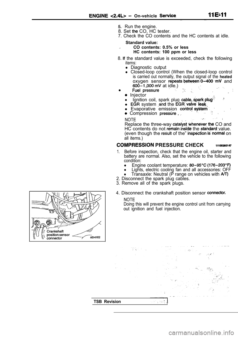
4. Disconnect the crankshaft position sensor
NOTE
Doing this will prevent the engine control unit fro m carrying
out ignition and fuel injection.
TSB Revision