oil temperature MITSUBISHI SPYDER 1990 Service Service Manual
[x] Cancel search | Manufacturer: MITSUBISHI, Model Year: 1990, Model line: SPYDER, Model: MITSUBISHI SPYDER 1990Pages: 2103, PDF Size: 68.98 MB
Page 589 of 2103
![MITSUBISHI SPYDER 1990 Service Service Manual ENGINE (TURBO)
AND ENGINE> Troubleshooting
INSPECTION PROCEDURE 11
When the engine is cold, it stalls at idle. (Die out)P r o b a b l e c a u s e .
[Comment]l Malfunction of the](/img/19/57345/w960_57345-588.png "MITSUBISHI SPYDER 1990 Service Service Manual ENGINE (TURBO)
AND ENGINE> Troubleshooting
INSPECTION PROCEDURE 11
When the engine is cold, it stalls at idle. (Die out)P r o b a b l e c a u s e .
[Comment]l Malfunction of the")
ENGINE (TURBO)
AND ENGINE> Troubleshooting
INSPECTION PROCEDURE 11
When the engine is cold, it stalls at idle. (Die out)P r o b a b l e c a u s e .
[Comment]l Malfunction of the system
In such cases as the above, the cause is probably t hat the mixture is inappropriate whenl the bodythe engine is cold, or that the intake air volume is insufficient.l Malfunction of the injector system Malfunction of the s y s t e m
W ere the battery terminals disconnected recently
NO
After warming-up, let the engine run at idling for 10 minutes.
SCAN TOOL DTC
Are diagnostic trouble codesoutput?Refer to INSPECTION CHART FOR TROUBLE CODES.
(Refer to Check and adjust the (Refer to ,
NO
Is engine-idling stable after the warming-up
YES(Refer to INSPECTION PROCEDURE
Check the idle air control motor for operation soun d NG
Engine (Turbo)>. (Refer to Check the idle air control motor for operation sound (Refer to
Checktheinjectorforope
OK
Check the idle control system malfunction to .INSPECTION PROCEDURE FOR DIAGNOSTIC TROUBLE CODE
PROCEDURE FOR DIAGNOSTIC TROUBLE CODES
SCAN TOOL Data list Check the closed position switch system.
26 Closed throttle position switch (Refer to INSPECTION PROCEDURE FOR
OKTROUBLE CODES
SCAN TOOL Data listN G Check the engine coolant temperature circuit malfu nction. (Refer to21 Enginecoolanttemperaturesensor P. I N S P E C T I O N P R O C E D U R E F O R TROUBLE CODES
Check the fuel pressure. (Refer to I
Check the ignition timing. Engine Check that the position sensor and belt cover are
(Refer to GROUP
(Refer to GROUP Check the ignition timing. Engine>
Check the following items.
l Check the ignition coil, spark plugs, spark plug ca bles.
l Check the compression pressure.
l Check the engine oil viscosity.
TSB Revision
Page 595 of 2103
![MITSUBISHI SPYDER 1990 Service Service Manual ENGINE (TURBO)
AND ENGINE> Troubleshooting
INSPECTION PROCEDURE 22
Too high CO and HC concentration when idling
[Comment]Malfunction of the ratio
Abnormal air-fuel ratio is susp](/img/19/57345/w960_57345-594.png "MITSUBISHI SPYDER 1990 Service Service Manual ENGINE (TURBO)
AND ENGINE> Troubleshooting
INSPECTION PROCEDURE 22
Too high CO and HC concentration when idling
[Comment]Malfunction of the ratio
Abnormal air-fuel ratio is susp")
ENGINE (TURBO)
AND ENGINE> Troubleshooting
INSPECTION PROCEDURE 22
Too high CO and HC concentration when idling
[Comment]Malfunction of the ratio
Abnormal air-fuel ratio is suspected.
SCAN TOOL Are diagnostic trouble codes output
N O
YES Refer to INSPECTION CHART FOR DIAGNOSTICTROUBLE CODES.
Check the ignition timing. Engine (Turbo)>NG
(Refer to GROUP On-vehicle Service.) Check that the crankshaft position sensor and belt installedCheck the ignition timing. Engine>(Refer to GROUP 11 On-vehicle Service.)
OK
NGSCAN TOOL Data list
21 Engine coolant temperature sensor. Check the engine coolant temperature malfunction. (Refer to
(Refer to INSPECTION PROCEDURE FOR DIAGNOSTIC
TROUBLE CODES
OK
SCAN TOOL Data listNG Check the intake air temperature (Refer to
13 Intake air temperature sensor (Refer to INSPECTION PROCEDURE FOR DIAGNOSTIC
OK TROUBLE CODE
SCAN TOOL Data list
25 Barometric pressure sensor (Refer to
OK
Check the pressure circuit malfunction. INSPECTION PROCEDURE FOR DIAGNOSTIC TROUBLE CODE
SCAN TOOL Data listNGCheck the oxygen sensor circuit malfunction (bank sensor 2). (Refer59 Heated oxygen sensor (rear) (Refer to to INSPECTION PROCEDURE FOR DIAGNOSTIC
l Transaxle gear TROUBLE CODE ranae l Driving with the throttle wide open
O K :
OK
SCAN TOOL Data list NG
Heated oxygen sensor (front) (Refer to OK: 1,000 when racing suddenly
OK
SCAN TOOL Data list11 Heated oxygen sensor (front) (Refer to O K : and
Check the oxygen sensor circuit malfunction (bank 1 sensor 1). INSPECTION PROCEDURE FOR DIAGNOSTICTROUBLE CODE
alternately when idling.
NG
Check the fuel pressure. (Refer to
Check the following items.
l Check the injectors for operation sound.
l Check the injectors for fuel leakage.
l Check the ignition coil, spark plugs, spark plug ca bles.
l Check the compression pressure.
l Check the positive crankcase ventilation system.
l Check the evaporative emission control system.
l Check the
system.I
Check trouble symptom.
Replace the three-way converter.
TSB Revision
Page 607 of 2103
![MITSUBISHI SPYDER 1990 Service Service Manual ENGINE (TURBO)
AND
ENGINE> Troubleshooting
INSPECTION PROCEDURE 35
Idle air control motor (DC motor) Engine>P r o b a b l e c a u s e
[Comment]l Malfunction of idle air control mo](/img/19/57345/w960_57345-606.png "MITSUBISHI SPYDER 1990 Service Service Manual ENGINE (TURBO)
AND
ENGINE> Troubleshooting
INSPECTION PROCEDURE 35
Idle air control motor (DC motor) Engine>P r o b a b l e c a u s e
[Comment]l Malfunction of idle air control mo")
ENGINE (TURBO)
AND
ENGINE> Troubleshooting
INSPECTION PROCEDURE 35
Idle air control motor (DC motor) Engine>P r o b a b l e c a u s e
[Comment]l Malfunction of idle air control motor
The ECM controls the intake air volume during idlin g by opening and closing the I m p r o p e r c o n n e c t o r open “circuit’ servo valve located in the bypass passage.
l Malfunction of the
at the idle air control motor connector Connect the connector. (Use test harness: Voltage between 5 and ground (Ignition switch: ON)
OK: 2 or more to 0 (momentarily) Voltage between 6 and ground (Ignition switch: ON)OK: 4 or more to 0 (momentarily)
OK
the idle air control motor.1
Check symptom.
Replace
INSPECTION PROCEDURE 36
Scan tool: Inspection when no initial combustion oc curs
SCAN TOOL Data listNGCheck the power and ignition 16 Voltage of ECM power source (Refer to (Refer to I PROCEDURE 27.)
(Whenoil filler cap is removed.)
SCAN TOOL DTC
Are the diagnostic trouble codes output
Check timing belt for breakage.
INSPECTION CHART FOR TROUBLE CODES.
(Refer to
SCAN TOOL list NG
22 Crankshaft position sensor OK: Cranking speed is displayed.
OK
Check the crankshaft position sensor circuit malfu nction. (Refer to INSPECTION PROCEDURE FOR DIAGNOSTIC
TROUBLE CODES
SCAN TOOL Actuator testCheck the fuel pump system Engine 07 Fuel pump (Refer to (Refer to INSPECTION PROCEDURE 28.)
OKCheck the fuel pump system (Refer to INSPECTION PROCEDURE 29) .
SCAN TOOL list21 Check the engine coolant temperature circuit (Refer to INSPECTION PROCEDURE FOR DIAGNOSTICTROUBLE CODES
TSB Revision
Page 622 of 2103
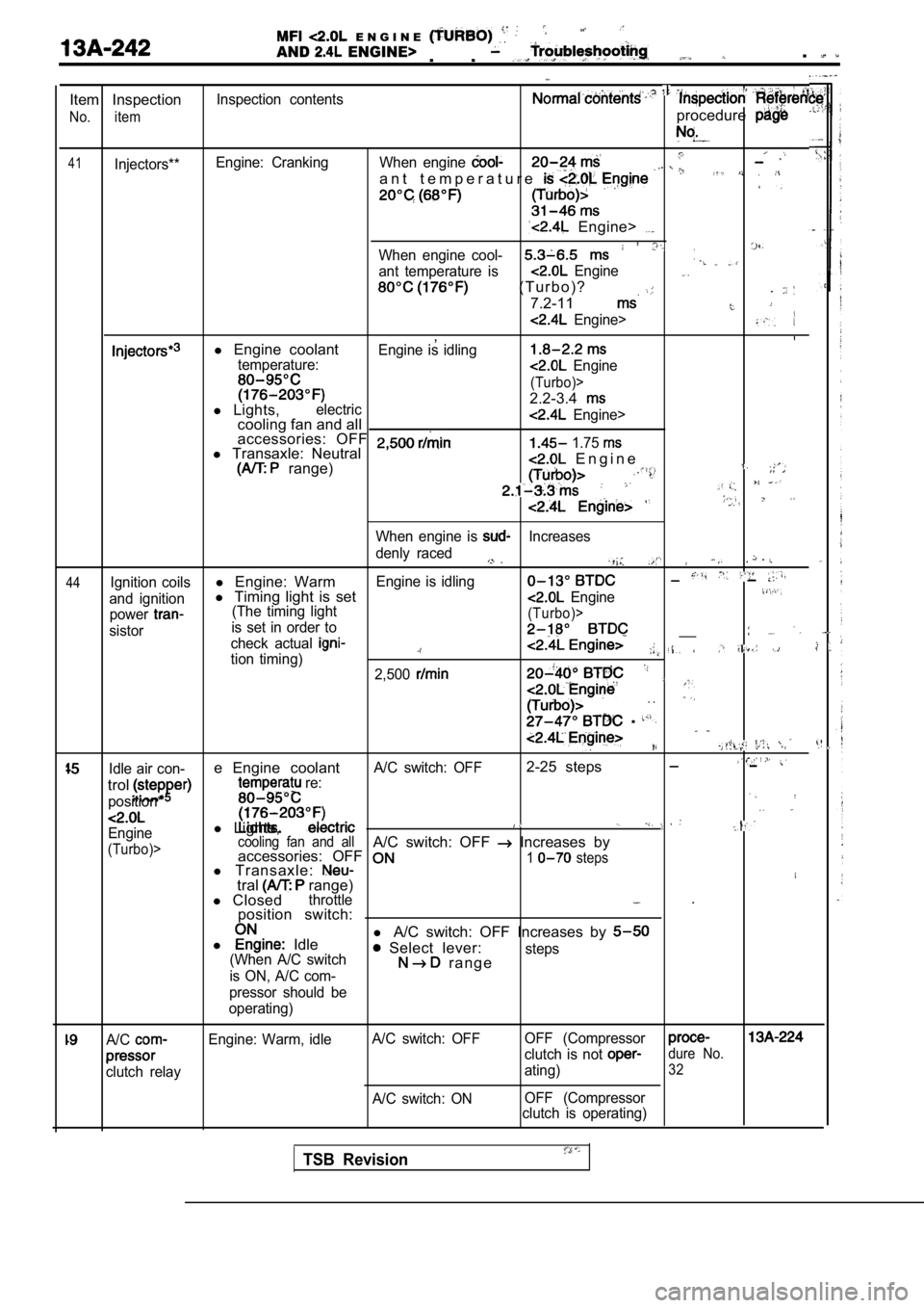
E N G I N E
AND ENGINE>. . .
Item Inspection
No. item
41Injectors**Inspection contents
Engine: Cranking
procedure
When engine
a n t t e m p e r a t u r e
Engine>
When engine cool-
ant temperature is Engine
( T u r b o ) ?
7.2-11
.
Engine>
,l Engine coolantEngine is idlingtemperature: Engine
(Turbo)>
2.2-3.4l Lights,electriccooling fan and all Engine>
accessories: OFF l Transaxle: Neutral 1.75
range) E n g i n e
44
When engine is Increases
denly raced
.
Ignition coilsl Engine: WarmEngine is idling
and ignitionl Timing light is set Engine
power(The timing light
sistor is set in order to(Turbo)>
check actual __
tion timing)2,500
. .
.
,
Idle air con-e Engine coolantA/C switch: OFF2-25 steps
trol
position*
re:
l
Lights,Engine
(Turbo)> cooling fan and allA/C switch: OFF Increases by
accessories: OFF
l Transaxle:1 steps
tral range)
l Closedthrottle .
position switch:
l
Idle l
A/C switch: OFF Increases by Select lever:(When A/C switch
is ON, A/C com- r a n g esteps
pressor should be
operating)
A/C
clutch relay Engine: Warm, idle
A/C switch: OFF
A/C switch: ON OFF (Compressor
clutch is not dure No.
ating)32
OFF (Compressor
clutch is operating)
TSB Revision
Page 638 of 2103
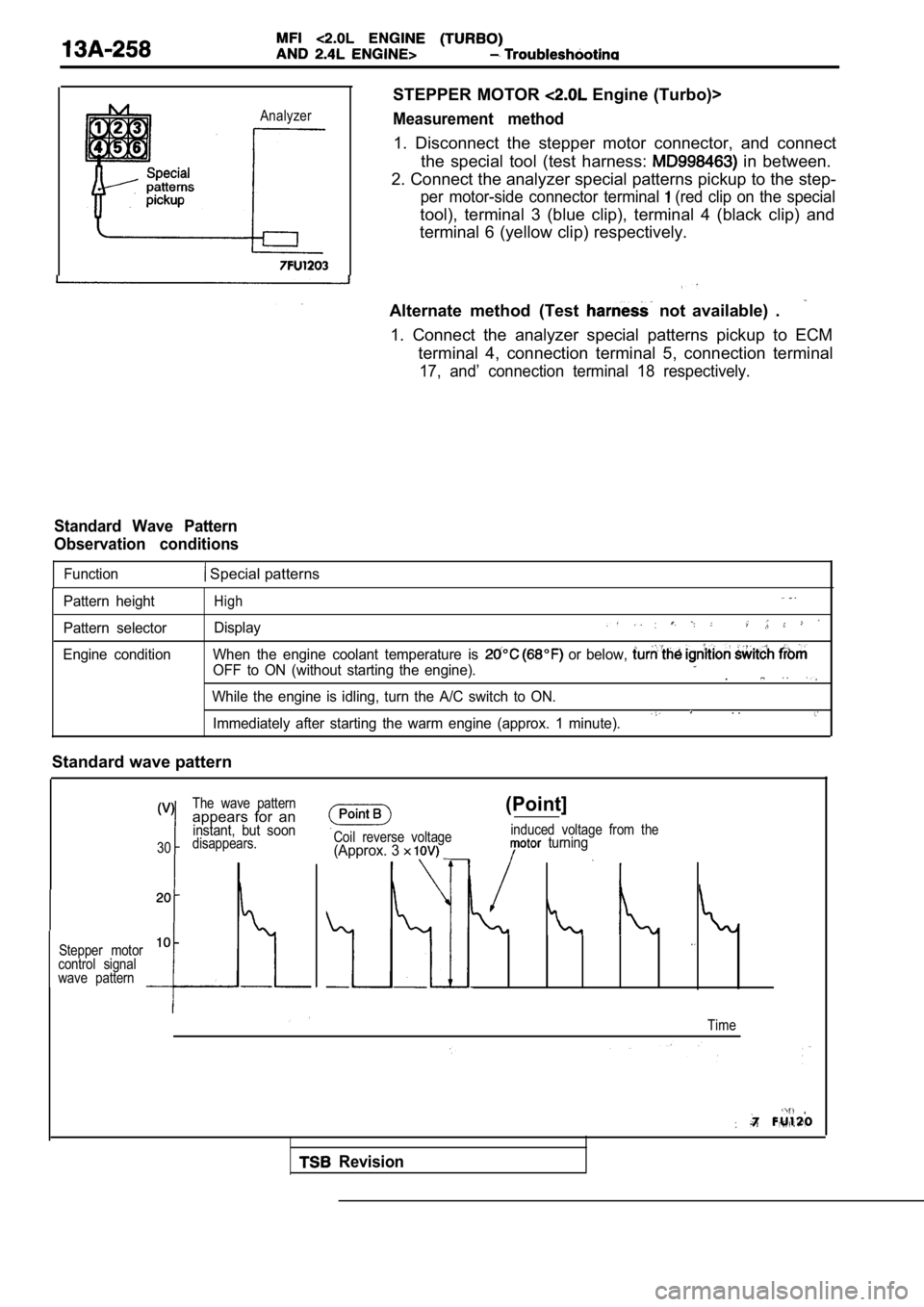
Analyzer
STEPPER MOTOR Engine (Turbo)>
Measurement method
1. Disconnect the stepper motor connector, and connect
the special tool (test harness:
in between.
2. Connect the analyzer special patterns pickup to the step-
per motor-side connector terminal (red clip on the special
tool), terminal 3 (blue clip), terminal 4 (black clip) and
terminal 6 (yellow clip) respectively.
Alternate method (Test
not available) .
1. Connect the analyzer special patterns pickup to ECM
terminal 4, connection terminal 5, connection termi nal
17, and’ connection terminal 18 respectively.
Standard Wave Pattern
Observation conditions
Function Special patterns
Pattern height
Pattern selector
Engine conditionHigh
Display
When the engine coolant temperature is or below,
OFF to ON (without starting the engine)..
While the engine is idling, turn the A/C switch to ON.. .Immediately after starting the warm engine (approx. 1 minute).
Standard wave pattern
The wave patternappears for aninstant, but soon
30disappears.
Stepper motor
10
control signal
wave pattern
Coil reverse voltage(Approx. 3
(Point]
induced voltage from the turning
Time
Revision
Page 652 of 2103
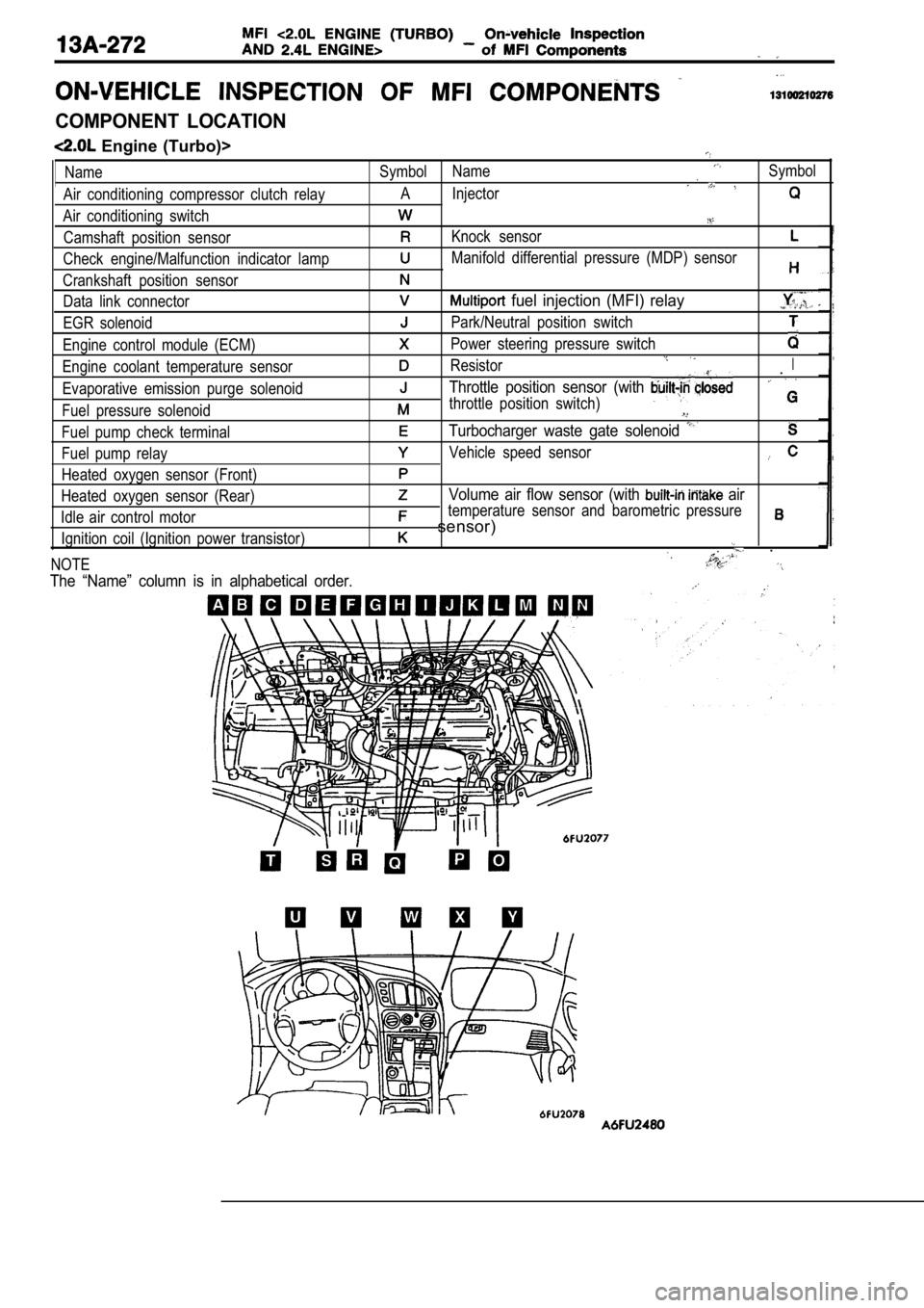
COMPONENT LOCATION
Engine (Turbo)>
Name
Air conditioning compressor clutch relay
Air conditioning switch Camshaft position sensor
Check engine/Malfunction indicator lamp
Crankshaft position sensor Data link connector
EGR solenoid
Engine control module (ECM)
Engine coolant temperature sensor
Evaporative emission purge solenoid
Fuel pressure solenoid
Fuel pump check terminal
Fuel pump relay
Heated oxygen sensor (Front)
Heated oxygen sensor (Rear)
Idle air control motor Ignition coil (Ignition power transistor)
NOTESymbol NameSymbol
A Injector
Knock sensor
Manifold differential pressure (MDP) sensor
fuel injection (MFI) relay
Park/Neutral position switch
Power steering pressure switch
ResistorI.
Throttle position sensor (with
throttle position switch)
Turbocharger waste gate solenoid
Vehicle speed sensor
Volume air flow sensor (with air
temperature sensor and barometric pressure
sensor)
.
The “Name” column is in alphabetical order.
Page 656 of 2103
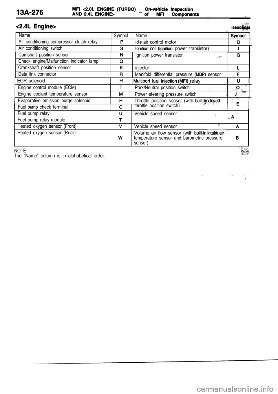
Name
Air conditioning compressor clutch relay
Air conditioning switchSymbol Name
air control motor
coil power transistor)
Camshaft position sensor
Check engine/Malfunction indicator lamp
Crankshaft position sensor
Data link connectorIgnition power transistor
injector
Manifold differential pressure sensor
EGR solenoid fuel relavI I
Engine control module (ECM)
Engine coolant temperature sensorPark/Neutral position switch
Power steering pressure switch
Evaporative emission purge solenoid
Fuel
check terminal
Throttle position sensor (with
throttle position switch)
Fuel pump relay
Fuel pump relay module
Heated oxygen sensor (Front)
Heated oxygen sensor (Rear)Vehicle speed sensor.
Vehicle speed sensor
Volume air flow sensor (with
temperature sensor and barometric pressure
sensor)
NOTE
The “Name” column is in alphabetical order.
Page 658 of 2103
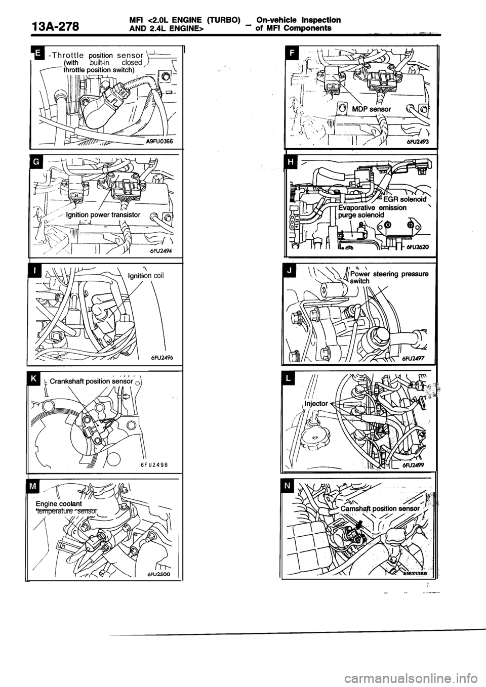
- T h r o t t l e sensor built-inclosed
on coil
temperature sensor
Page 692 of 2103
14-2ENGINE COOLING General Information
GENERAL INFORMATION , ,
The cooling system is designed to keep every partthat the heat absorbed by the coolant may be of the engine at appropriate temperature in diated into the air.
er condition the engine may be operated.
The cooling of the water-cooled, pressureThe water pump is of the centrifugal type and is
driven by the
the
forced circulation type in which the water pump crankshaft. .
pressurizes coolant and circulates it throughout th e
engine: If the coolant temperature exceeds the
scribed temperature, the thermostat opens to circu-
late the coolant through the radiator as well so
and is cooled the
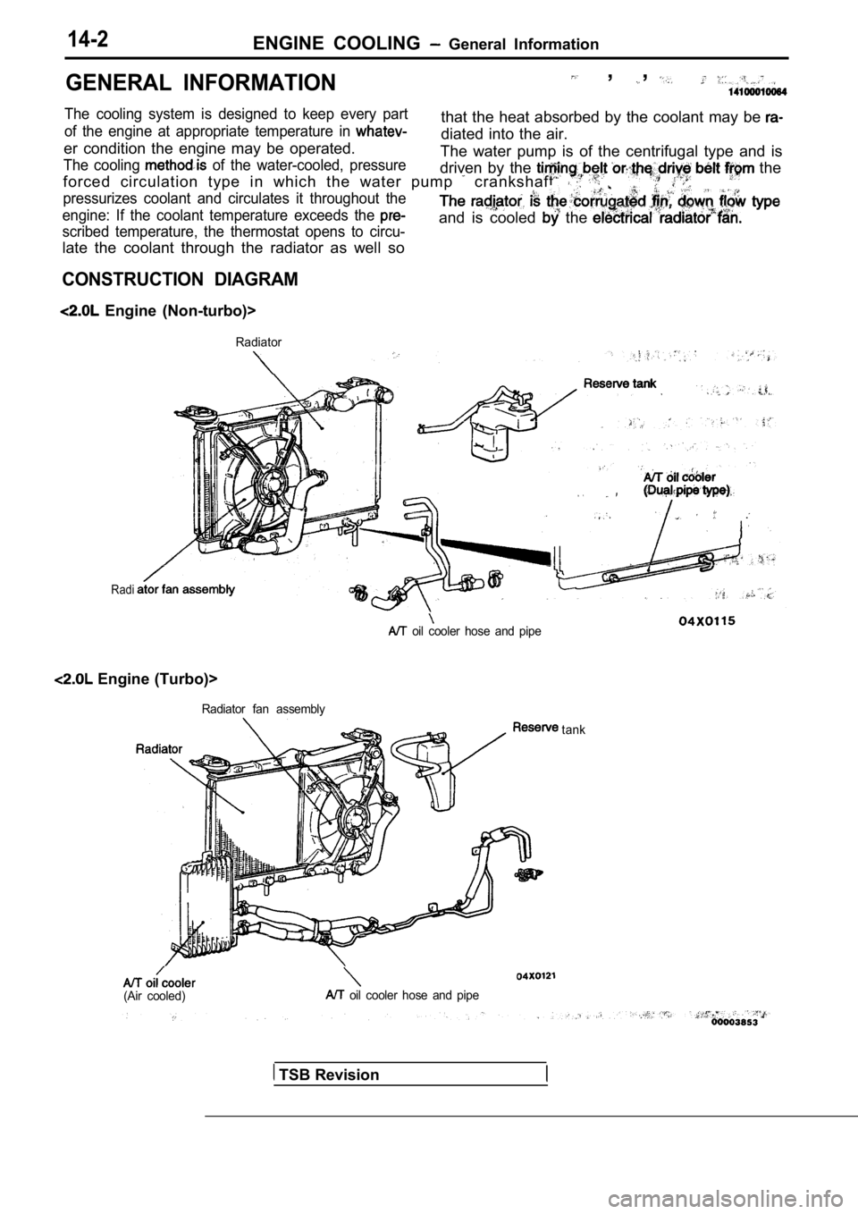
CONSTRUCTION DIAGRAM
Engine (Non-turbo)>
Radiator
Radi
.
oil cooler hose and pipe
Engine (Turbo)>
Radiator fan assembly
(Air cooled) oil cooler hose and pipetank
TSB Revision
Page 693 of 2103
G e n e r a l
ENGINE COOLING
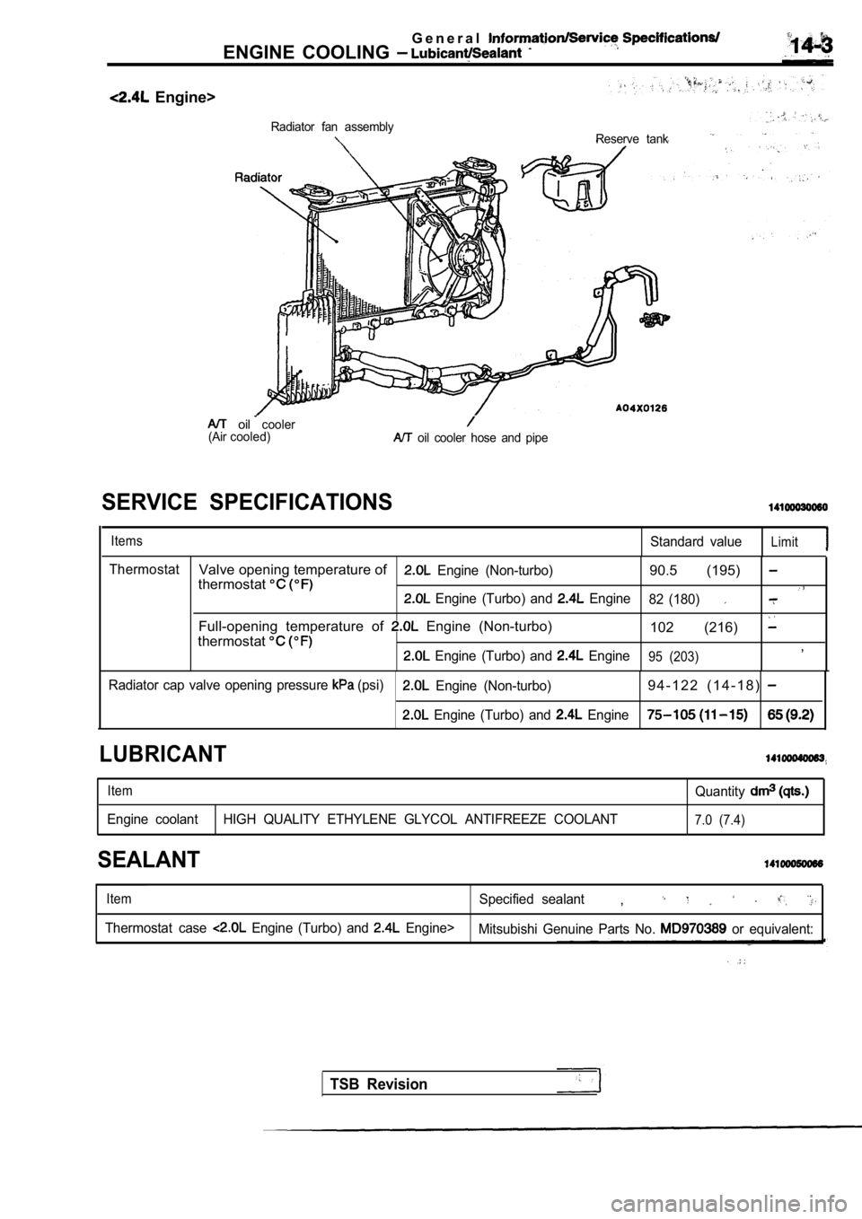
Engine>
Radiator fan assemblyReserve tank
(Airoilcooler
cooled) oil cooler hose and pipe
SERVICE SPECIFICATIONS
ItemsStandard valueLimit
ThermostatValve opening temperature of Engine (Non-turbo)90.5 (195) thermostat Engine (Turbo) and Engine 82 (180)
Full-opening temperature of Engine (Non-turbo)
102 (216)
thermostat
Engine (Turbo) and Engine95 (203),
Radiator cap valve opening pressure (psi) Engine (Non-turbo)9 4 - 1 2 2 ( 1 4 - 1 8 )
Engine (Turbo) and Engine
LUBRICANT
ItemQuantity
Engine coolant HIGH QUALITY ETHYLENE GLYCOL ANTIFREE ZE COOLANT7.0 (7.4)
SEALANT
ItemSpecified sealant,
Thermostat case Engine (Turbo) and Engine>
Mitsubishi Genuine Parts No. or equivalent:
TSB Revision