engine oil MITSUBISHI SPYDER 1990 Service Manual PDF
[x] Cancel search | Manufacturer: MITSUBISHI, Model Year: 1990, Model line: SPYDER, Model: MITSUBISHI SPYDER 1990Pages: 2103, PDF Size: 68.98 MB
Page 135 of 2103
ENGINE OVERHAUL Rocker Arms and
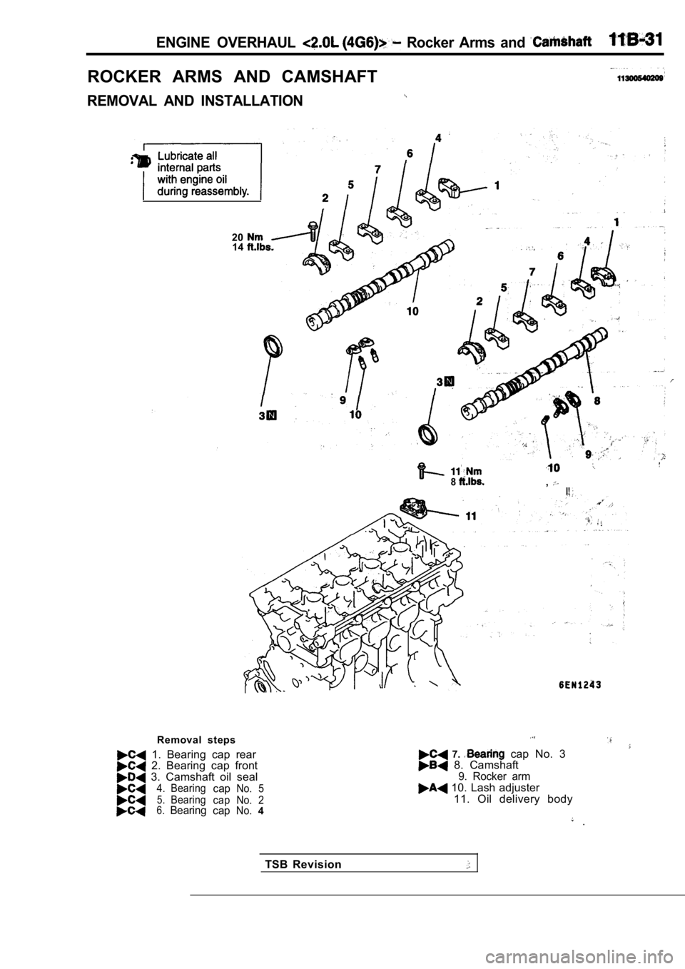
ROCKER ARMS AND CAMSHAFT
REMOVAL AND INSTALLATION
2014
8,I!
Removal steps
1. Bearing cap rear 2. Bearing cap front 3. Camshaft oil seal4. BearingcapNo. 55.Bearingcap No. 26.BearingcapNo.4
7. cap No. 3 8. Camshaft9. Rocker arm 10. Lash adjuster
11. Oil delivery body
.
TSB Revision
Page 136 of 2103
ENGINE OVERHAUL Rocker, Arms
Camshaft sprocket side
sidecamshaft
Dowel pin
n0
Cap number
Symbol identifying
intake or exhaust
0
Camshaft sprocket side1197 810 12
2 6
I N S T A L L A T I O N S E R V I C E
L A S H A D J U S T E R
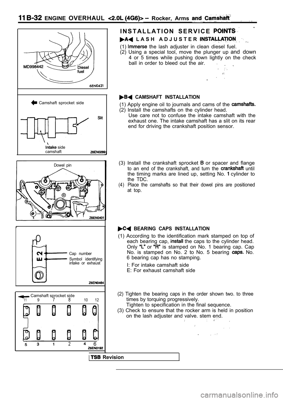
(1) the lash adjuster in clean diesel fuel.
(2) Using a special tool, move the plunger up and down
4 or 5 times while pushing down lightly on the chec k
ball in order to bleed out the air.
,
CAMSHAFT INSTALLATION
(1) Apply engine oil to journals and cams of the
(2) Install the camshafts on the cylinder head. Use care not to confuse the intake camshaft with th e
exhaust one. The intake camshaft has a slit on its rear
end for driving the crankshaft position sensor.
(3) Install the crankshaft sprocket
or spacer and flange
to an end of the crankshaft, and turn the until
the timing marks are lined up, setting No. cylinder to
the TDC.
(4)Place the camshafts so that their dowel pins are po sitioned
at top.
BEARING CAPS INSTALLATION
(1) According to the identification mark stamped on top of
each bearing cap,
the caps to the cylinder head.
Only
or is stamped on No. 1 bearing cap. Cap
No. is stamped on No. 2 to No. 5 bearing
No.
6 bearing cap has no stamping.
I: For intake camshaft side
E: For exhaust camshaft side
(2) Tighten the bearing caps in the order shown two . to three
times by torquing progressively.
Tighten to specification in the final sequence.
(3) Check to ensure that the rocker arm is held in position
on the lash adjuster and valve. stem end.
.
Revision
Page 137 of 2103
ENGINE OVERHAUL R o c k e r
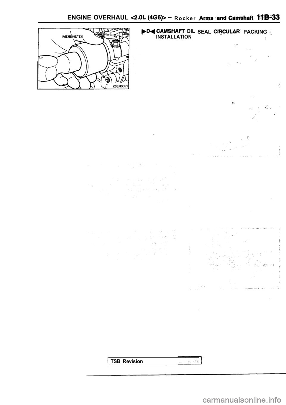
OIL
INSTALLATION
SEAL PACKING
TSB Revision
Page 141 of 2103
ENGINE OVERHAUL Cylinder Head and Valves
colorSpring
retainer
Stem seal
, Spring seat
REMOVAL
PRECAUTION FOR PARTS
(1) Keep removed parts in order according to the cy linder,
number and intake/exhaust.
H E A D B O L T S R E M O V A L
(1) Using the special tool, the cylinder bolts.
Loosen evenly, little by little.
,
L O C K R E M O V A L
(1) Store removed valves, springs and other parts,‘ tagged
to indicate their cylinder No. and location for reassembly.
STEM SEAL REMOVAL
(1) Do not reuse valve stem seal.
INSTALLATION SERVICE POINTS
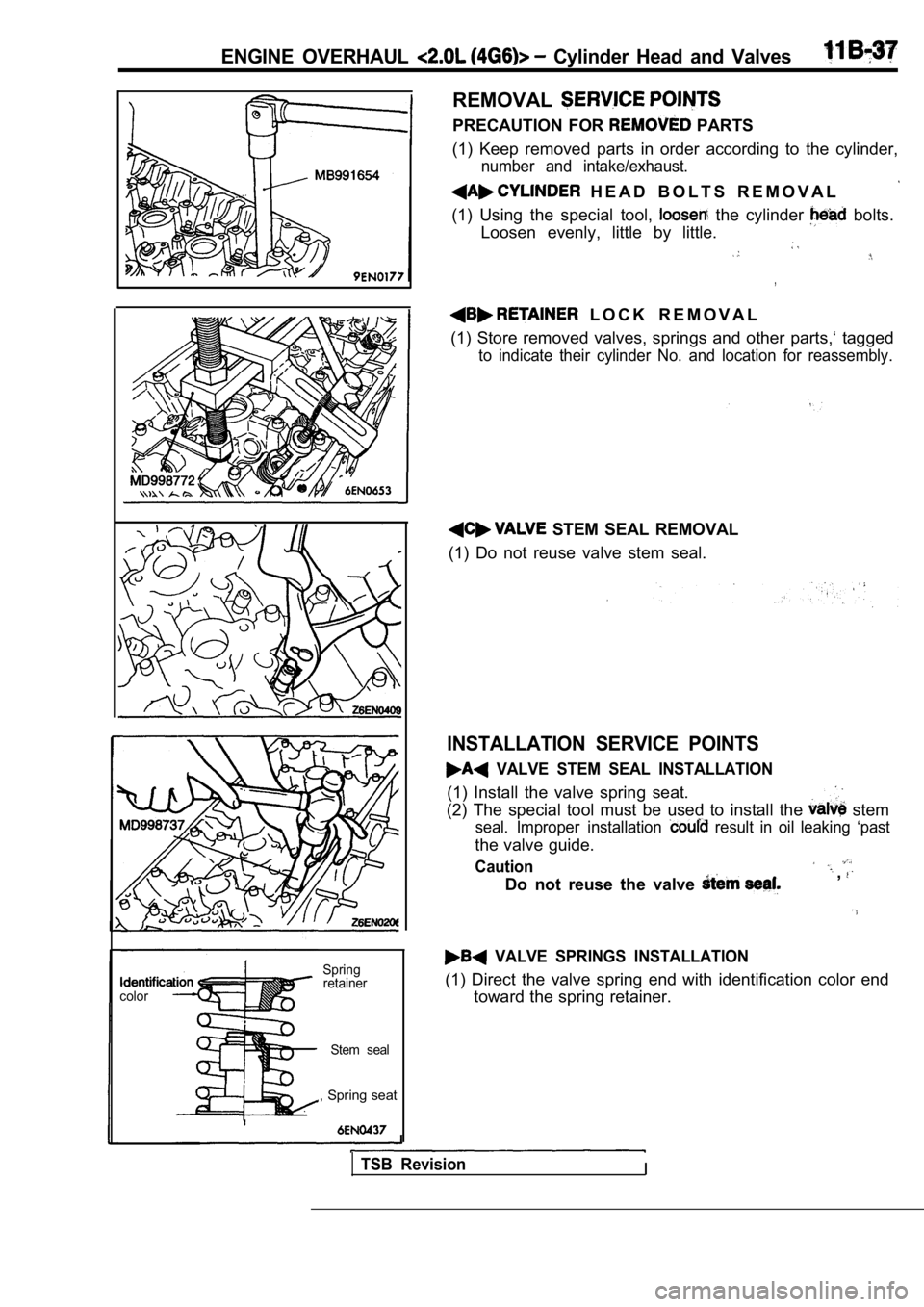
VALVE STEM SEAL INSTALLATION
(1) Install the valve spring seat.
(2) The special tool must be used to install the
stem
seal. Improper installation result in oil leaking ‘past
the valve guide.
Caution
Do not reuse the valve ,
VALVE SPRINGS INSTALLATION
(1) Direct the valve spring end with identification color end
toward the spring retainer.
TSB RevisionI
Page 142 of 2103
11 E N G I N E O V E R H A U L Cylinder Head
Identification mark
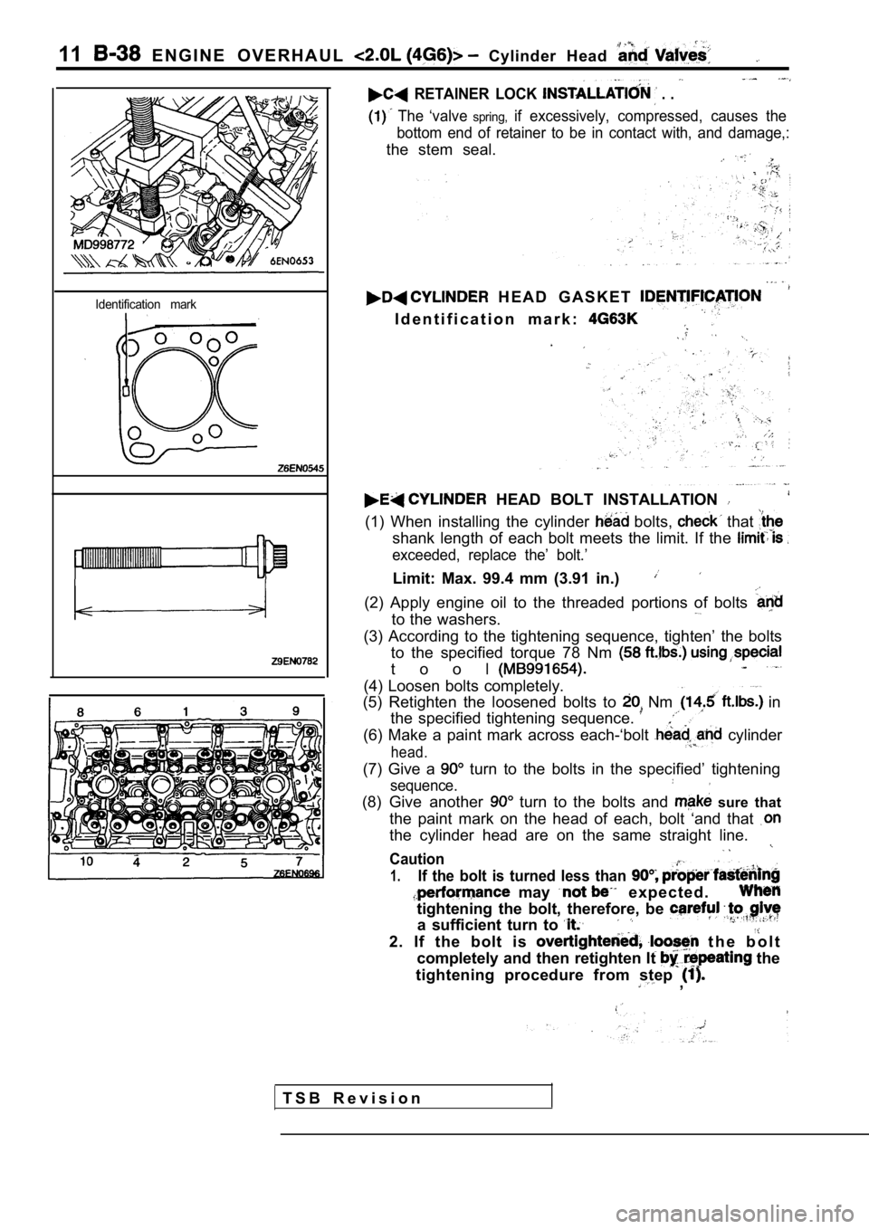
RETAINER LOCK . .
The ‘valve spring,if excessively, compressed, causes the
bottom end of retainer to be in contact with, and d amage,:
the stem seal.
H E A D G A S K E T
I d e n t i f i c a t i o n m a r k :
HEAD BOLT INSTALLATION
(1) When installing the cylinder bolts, that
shank length of each bolt meets the limit. If the
exceeded, replace the’ bolt.’
Limit: Max. 99.4 mm (3.91 in.)
(2) Apply engine oil to the threaded portions of bo lts
to the washers.
(3) According to the tightening sequence, tighten’ the bolts
to the specified torque 78 Nm
t o o l
(4) Loosen bolts completely.
(5) Retighten the loosened bolts to
Nm in
the specified tightening sequence.
(6) Make a paint mark across each-‘bolt cylinder
head.
(7) Give a turn to the bolts in the specified’ tightening
sequence.
(8) Give another turn to the bolts and sure that
the paint mark on the head of each, bolt ‘and that
the cylinder head are on the same straight line.
Caution
1.If the bolt is turned less than
may e x p e c t e d .
tightening the bolt, therefore, be
a sufficient turn to
2. If the bolt is t h e b o l t
completely and then retighten It
the
tightening procedure from step
,
T S B R e v i s i o n
Page 146 of 2103
ENGINE OVERHAUL.
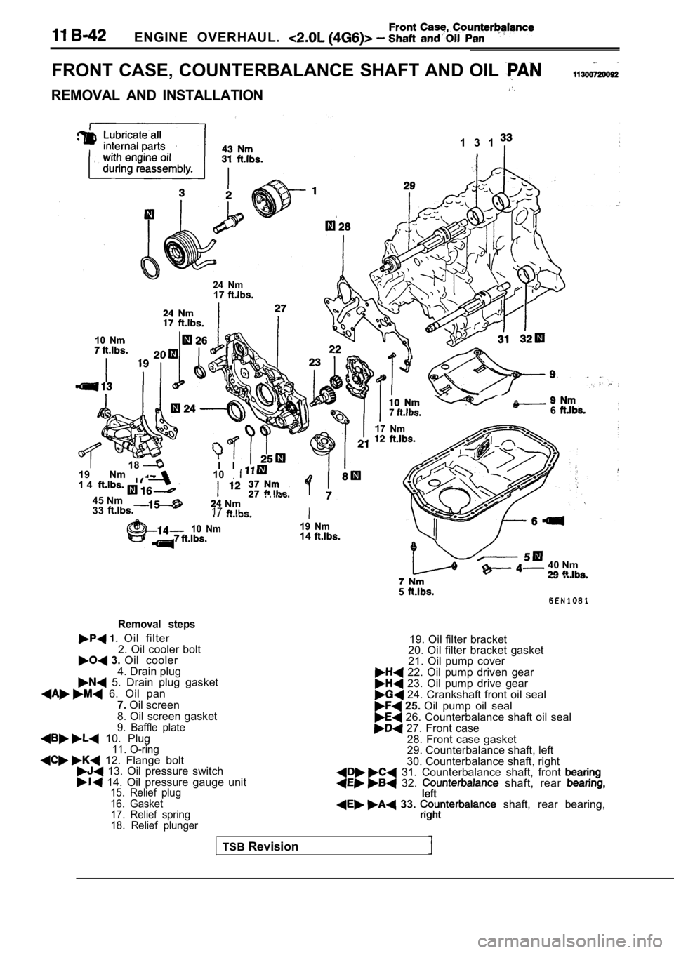
FRONT CASE, COUNTERBALANCE SHAFT AND OIL
REMOVAL AND INSTALLATION
1 3 1
24 Nm17
10 Nm
I18I I
76
17 Nm
19 Nm 101 4
45 Nm
33. . Nm
17I
10 Nm19 Nm14
40 Nm
5
Removal steps
Oil filter
2. Oil cooler bolt
3. Oil cooler
4. Drain plug
5. Drain plug gasket
6. Oil pan
7.Oil screen
8. Oil screen gasket
9. Baffle plate 10. Plug11. O-ring 12. Flange bolt 13. Oil pressure switch 14. Oil pressure gauge unit15. Relief plug
16. Gasket 17. Relief spring
18. Relief plunger
TSB Revision 19. Oil filter bracket
20. Oil filter bracket gasket
21. Oil pump cover
22. Oil pump driven gear 23. Oil pump drive gear 24. Crankshaft front oil seal
25. Oil pump oil seal 26. Counterbalance shaft oil seal 27. Front case
28. Front case gasket
29. Counterbalance shaft, left
30. Counterbalance shaft, right
31. Counterbalance shaft, front 32. shaft, rear
33. shaft, rear bearing,
Page 147 of 2103
Front Case,
ENGINE OVERHAUL and Pan
Phillips screwdriver
F r o n tbearing
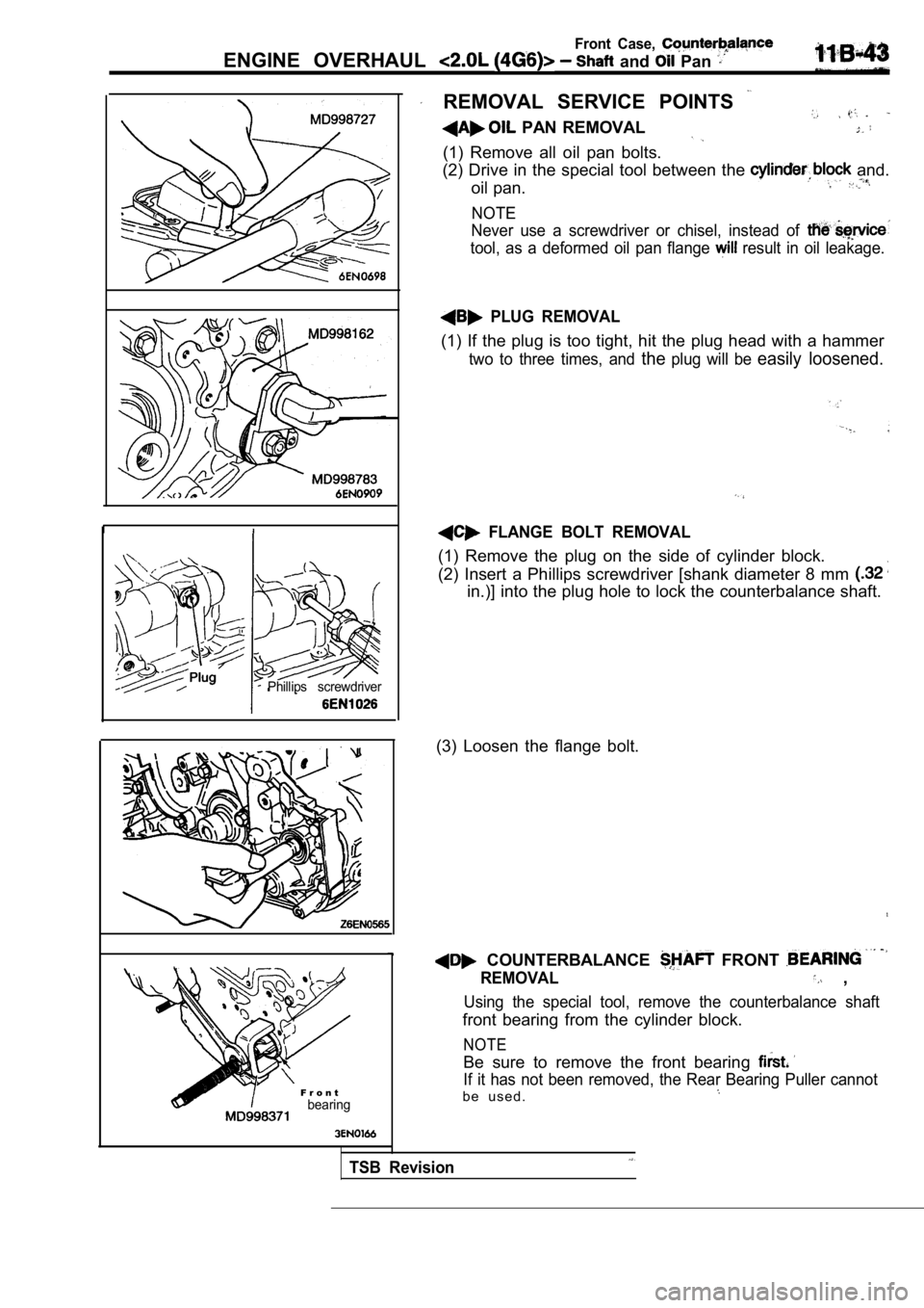
REMOVAL SERVICE POINTS
PAN REMOVAL
(1) Remove all oil pan bolts.
(2) Drive in the special tool between the
and.
oil pan.
NOTE
Never use a screwdriver or chisel, instead of
tool, as a deformed oil pan flange result in oil leakage.
PLUG REMOVAL
(1) If the plug is too tight, hit the plug head wit h a hammer
two to three times, and theplug will be easily loosened.
FLANGE BOLT REMOVAL
(1) Remove the plug on the side of cylinder block.
(2) Insert a Phillips screwdriver [shank diameter 8 mm
in.)] into the plug hole to lock the counterbalance shaft.
(3) Loosen the flange bolt.
COUNTERBALANCE FRONT
REMOVAL ,
Using the special tool, remove the counterbalance s haft
front bearing from the cylinder block.
NOTE
Be sure to remove the front bearing
If it has not been removed, the Rear Bearing Puller cannot
b e u s e d .
TSB Revision
Page 148 of 2103
11Front Case, ENGINE OVERHAUL Shaft and
Rear bearing
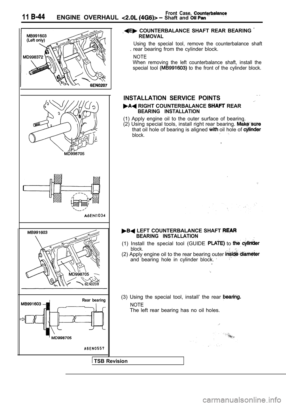
COUNTERBALANCE SHAFT REAR BEARING
REMOVAL
Using the special tool, remove the counterbalance shaft
. rear bearing from the cylinder block.
NOTE
When removing the left counterbalance shaft, install the
special tool
to the front of the cylinder block.
INSTALLATION SERVICE POINTS
RIGHT COUNTERBALANCE REAR
BEARING INSTALLATION
(1) Apply engine oil to the outer surface of bearin g.
(2) Using special tools, install right rear bearing .
that oil hole of bearing is aligned oil hole of
block.
,
LEFT COUNTERBALANCE SHAFT
BEARING INSTALLATION
(1) Install the special tool (GUIDE to
block.
(2) Apply engine oil to the rear bearing outer
and bearing hole in cylinder block.
(3) Using the special tool, install’ the rear
NOTE
The left rear bearing has no oil holes.
TSB Revision
Page 149 of 2103
Front Case, Counterbalance
ENGINE OVERHAUL Shaft and
C y l i n d e rblock
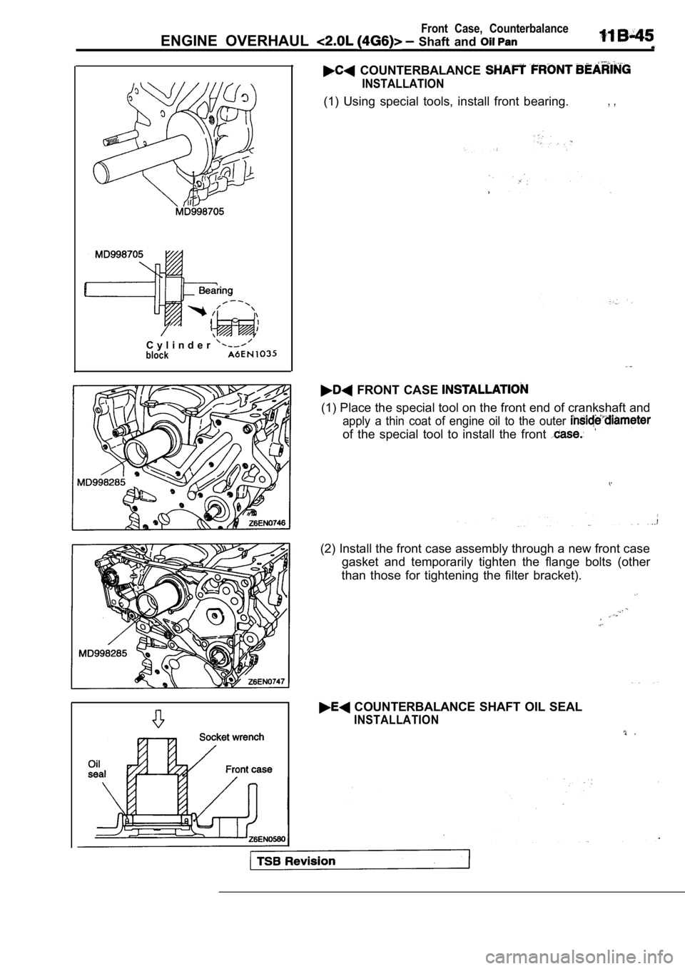
COUNTERBALANCE
INSTALLATION
(1) Using special tools, install front bearing., ,
FRONT CASE
(1) Place the special tool on the front end of crankshaft and
apply a thin coat of engine oil to the outer
of the special tool to install the front
(2) Install the front case assembly through a new f ront case
gasket and temporarily tighten the flange bolts (ot her
than those for tightening the filter bracket).
COUNTERBALANCE SHAFT OIL SEAL
INSTALLATION
Page 150 of 2103
11Front Case, ENGINE OVERHAUL Shaft and
Socket
Oil seal
case
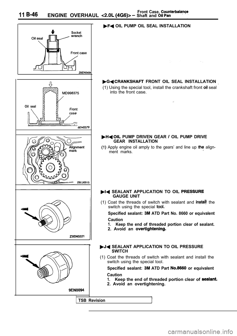
OIL PUMP OIL SEAL INSTALLATION
FRONT OIL SEAL INSTALLATION
(1) Using the special tool, install the crankshaft front seal
into the front case.
PUMP DRIVEN GEAR OIL PUMP DRIVE
GEAR INSTALLATION
Apply engine oil amply to the gears’ and line up align-
ment marks.
SEALANT APPLICATION TO OIL
GAUGE UNIT
(1) Coat the threads of switch with sealant and
the
switch using the special
Specified sealant: ATD Part No. 8660 or equivalent
Caution
1.Keep the end of threaded portion clear of sealant.
2. Avoid an
SEALANT APPLICATION TO OIL PRESSURE
SWITCH
(1) Coat the threads of switch with sealant and ins tall the
switch using the special tool.
Specified sealant: ATD Part or equivalent
Caution
1.Keep the end of threaded portion clear of
2. Avoid an overtightening.
TSB Revision