MITSUBISHI SPYDER 1990 Service Repair Manual
Manufacturer: MITSUBISHI, Model Year: 1990, Model line: SPYDER, Model: MITSUBISHI SPYDER 1990Pages: 2103, PDF Size: 68.98 MB
Page 741 of 2103
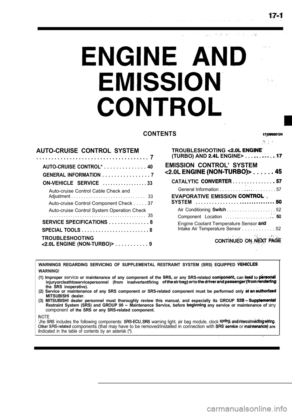
CONTENTS
AUTO-CRUISE CONTROL SYSTEM
. . . . . . . . . . . . . . . . . . . . . . . . . . . . . . . . . . . . .7
AUTO-CRUISE CONTROL* . . . . . . . . . . . . . . 40
GENERAL INFORMATION . . . . . . . . . . . . . . . . 7
ON-VEHICLE SERVICE. . . . . . . . . . . . . . . . . 33
Auto-cruise Control Cable Check and
Adjustment . . . . . . . . . . . . . . . . . . . . . . . . . . . . . .
33
Auto-cruise Control Component Check . . . . . 37
Auto-cruise Control System Operation Check
. . . . . . . . . . . . . . . . . . . . . . . . . . . . . . . . . . . . . . . . .
35
SERVICE SPECIFICATIONS . . . . . . . . . . . . . 8
SPECIAL TOOLS . . . . . . . . . . . . . . . . . . . . . . . . 8
TROUBLESHOOTING
ENGINE (NON-TURBO)> . . . . . . . . . . . 9
TROUBLESHOOTING
(TURBO) AND ENGINE> . . . . .
EMISSION CONTROL’ SYSTEM
. . . . .
CATALYTIC . . . . . . . . . . . . . .
General Information . . . . . . . . . . . . . . . . . . 57
EVAPORATIVE EMISSION .
SYSTEM. . . . . . . . . . . . . . . .
Air Conditioning . . . . . . . . . . . . . . . . . . . 52
Component Location
. . . . . . . . . . . . . . . . . .
Engine Coolant Temperature Sensor
Intake Air Temperature Sensor . . . . . . . . . . . . 52
WARNINGS REGARDING SERVICING OF SUPPLEMENTAL RESTRA INT SYSTEM (SRS) EQUIPPED
WARNING!
(1) Improper serviceor maintenance of any component of the or any SRS-related can to injuryorcleathtoservicepersonnel (from inadvertentfiring the SRS inoperative).
(2) Service or maintenance of any SRS component or SRS-related component must be performed only
MITSUBISHI dealer.
(3) MITSUBISHI dealer personnel must thoroughly rev iew this manual, and especially its GROUP
Restraint System (SRS) and GROUP 00 Maintenance Service, before any service or maintenance of any
componentof the SRS or any SRS-related component.
NOTEJhe includes the following components: warning light, air bag module, clock components (that may have to be removed/installed in connection with or areIndicated in the table of contents by an asterisk
Page 742 of 2103
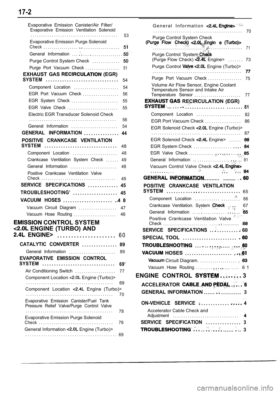
17-2
Evaporative Emission Canister/Air Filter/
Evaporative Emission Ventilation Solenoid
. . . . . . . . . . . . . . . . . . . . . . . . . . . . . . . . . . . . . . . . .53
Evaporative Emission Purge Solenoid
Check. . . . . . . . . . . . . . . . .. . . . . . . . . . . . . . . . . . .
General Information. . .. . .. . . . . . . . . . . . . . .
Purge Control System Check. . . . . . . . . . . . .
Purge Port Vacuum Check. . . . . . . . . . . . . . . .51
EXHAUST GAS (EGR)
SYSTEM. . . . . . . . . . . . . . . . . . . . . . . . . . . . . . . 54
Component Location. . . . . . . . . . . . . . . . . . . . .54
EGR Port Vacuum Check. . . . . . . . . . . . . . . . .56
EGR System Check. . . . . . . . . . . . . . . . . . . . . .55
EGR Valve Check. . . . . . . . . . . . . . . . . . . . . . . .55
Electric EGR Transducer Solenoid Check
. . . . . . . . . . . . . . . . . . . . . . . . . . . . . . . . . . . . . . . . .
56
General Information. . . . . . . . . . . . . . . . . . . . . .54
GENERAL INFORMATION. . . . . . . . . . . . . . .44
POSITIVE CRANKCASE VENTILATION
SYSTEM. . . . . . . . . . . . . . . . . . . . . . . . . . . . . . . 48
Component Location. . . . . . . . . . . . . . . . . . . . .48
Crankcase Ventilation System Check. . . . . .49
General Information. . . . . . . . . . . . . . . . . . . . . .48
Positive Crankcase Ventilation Valve
Check. . . . . . . . . . . . . . . . . . . . . . . . . . . . . . . . . . .49
SERVICE SPECIFICATIONS. . . . . . . . . . . . .45
TROUBLESHOOTING’
. . . . . . . . . . . . . . . . . . .45
VACUUM HOSES. . . . . . . . . . . . . . . . . . . . . ..4 8
Vacuum Circuit Diagram. . . . . . . . . . . . . . . . . .47
Vacuum Hose Routing
. . . . . . . . . . . . . . . . . . . .46
CONTROL SYSTEM
ENGINE (TURBO) AND
ENGINE>. . . . . . . . . . . . . . . . . . . . . 6 0
CATALYTIC CONVERTER. . . . . . . . . . . . . . .89
General Information. . . . . . . . . . . . . . . . . . . . . .89
EVAPORATIVE EMISSION CONTROL
SYSTEM. . . . . . . . . . . . . . . . . . . . . . . . . . . . . . .69’
Air Conditioning Switch
. . . . . . . . . . . . . . . . . . .77
Component Location Engine (Turbo)>
. . . . . . . . . . . . . . . . . . . . . . . . . . . . . . . . . . . . . . . . .
69
Component Location Engine (Turbo)>
. . . . . . . . . . . . . . . . . . . . . . . . . . . . . . . . . . . . . . . . .
70
Evaporative Emission Canister/Fuel Tank
Pressure Relief Valve/Purge Control Valve
. . . . . . . . . . . . . . . . . . . . . . . . . . . . . . . . . . . . . . . . .78
Evaporative Emission Purge Solenoid
Check. . . . . . . . . . . . . . . . . . . . . . . . . . . . . . . . . . .76
General Information Engine (Turbo)> G e n e r a l I n f o r m a t i o n
. . . . . . . . . . . . . . . . . .
. . . . . . . . . . . . . . . . . . . . . . .70
Purge Control System Check
. . . . . . . . . . . . . . . . . . . . . . . . . .. . . . . . . . . . . . . . . .71
Purge Control ‘System
(Purge Flow Check) Engine>. . . . . . .73
Purge Control Engine (Turbo)>
. . . . . . . . . . . . . . . . . . . . . . . . . . . . . . . . . . . . . . . . . .
Purge Port Vacuum Check. . . . . . . . . . . . . . . .75
Volume Air Flow Sensor, Engine Coolant
Temperature Sensor and Intake Air
Temperature Sensor. . . . . . . . . . . . . . . . . . . . . . .77
RECIRCULATION (EGR)
.... . .. . . . . . . . . . . . . . . . . . . . . . . .81
Component Location. . . . . . . . . . . . . . . . . . . . .82
EGR Port Vacuum Check . . . . . . . . . . . . . . . . .86
EGR Solenoid Check Engine (Turbo)>
. . . . . . . . . . . . . . . . . . . . . . . . . . . . . . . . . . . . . . . . .
87
EGR Solenoid Check Engine>. . . . . .
EGR System Check . . . . . . . . . . . . . . . . . .
EGR Valve Check. . . . . . . . . . . . .. . .
General Information... . . . . . . . . . . . . .....81
Vacuum Control Valve Check
. . . . . . . . .
.......................................
POSITIVE CRANKCASE VENTILATION
SYSTEM
. . . . . . . ... . .. . . . . . . . . . . . . . . . . 65
Component Location. . . . . . . . . . . . .. . . . . . . . .66
Crankcase Ventilation. System . .67
General Information
. . . .. . . . . ... . ........
Positive Crankcase Ventilation Valve
Check. . . . . . . . . . . . . . . . . . . . . ... . ............
SERVICE SPECIFICATIONS. .. . . . . . . . . 60
SPECIAL TOOL . . . . . . . . . . . . . . . . . . . . . . .
. . .. .
HOSES
. . . . ..
. . . . . . . . . . . . . . . . . . . . .,
Circuit Diagram.. . . . . . . . . . . . . . . . . . ,
Vacuum Hose Routing. . . . . . . ...... . . . 6 1
ENGINE CONTROL
3
ACCELERATOR
......
GENERAL INFORMATION . . . . . .. . . . . . . . . .3
ON-VEHICLE SERVICE. . . . . . . . . . . .4
Accelerator Cable Check and
Adjustment. . . . . . . . . . . . . . . . . . . . . . . . . . . . . . .
SERVICE SPECIFICATION. . . . . . . . . . . . . . .3
. ... . . . . ...3. . . . . . . . . . . . . . . . . . . . . . . . . . . . . . . . . . . . . . . . .
69
Page 743 of 2103
ENGINE AND EMISSION CONTROL Engine Control System
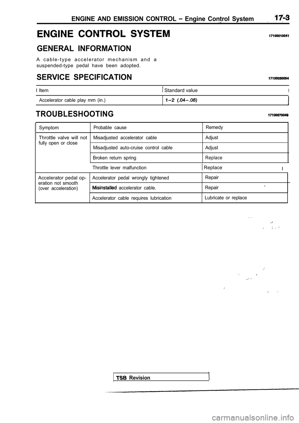
GENERAL INFORMATION
A c a b l e - t y p e a c c e l e r a t o r m e c h a n i s m a n d asuspended-type pedal have been adopted.
SERVICE SPECIFICATION
I Item Standard valueI
Accelerator cable play mm (in.)
TROUBLESHOOTING
Symptom Probable cause Remedy
Throttle valve will notMisadjusted accelerator cable
Adjust
fully open or close Misadjusted auto-cruise control cable Adjust
Broken return spring
Replace
Throttle lever malfunction Replace I
Accelerator pedal op-
Accelerator pedal wrongly tightened Repair
eration not smooth (over acceleration)
accelerator cable. Repair
Accelerator cable requires lubrication Lubricate or replace
Revision
Page 744 of 2103
ENGINE AND EMISSION CONTROL Engine Control
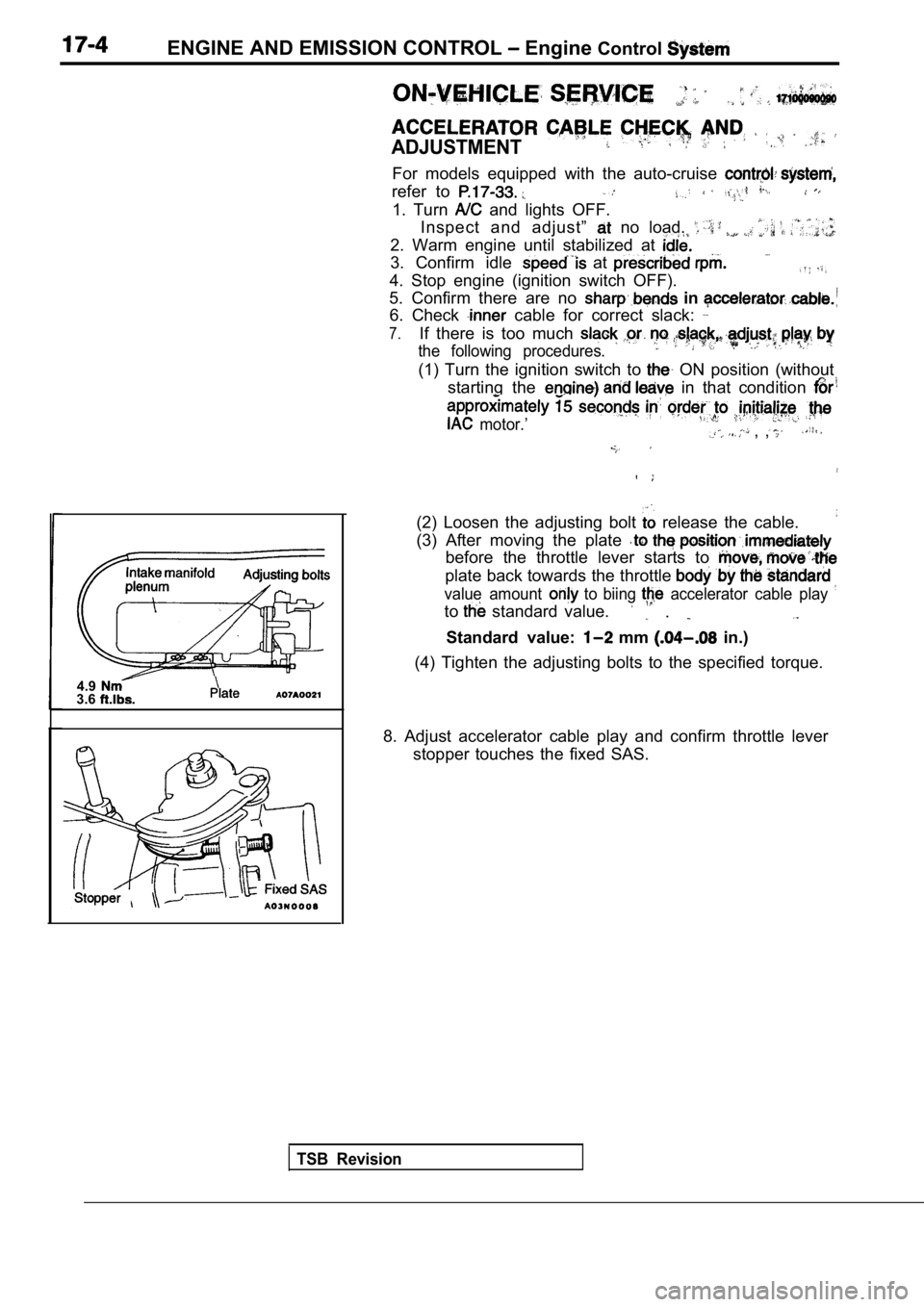
ADJUSTMENT
For models equipped with the auto-cruise
refer to
1. Turn and lights OFF.
Inspect and adjust”
no load.
2. Warm engine until stabilized at
3. Confirm idle at
4. Stop engine (ignition switch OFF).
5. Confirm there are no in
6. Check cable for correct slack:
7.If there is too much
the following procedures.
(1) Turn the ignition switch to ON position (without
starting the
in that condition
motor.’ , ,
4.93.6
TSB Revision
(2) Loosen the adjusting bolt release the cable.
(3) After moving the plate
before the throttle lever starts to
plate back towards the throttle
value amount to biing accelerator cable play
to standard value. .
Standard value: mm in.)
(4) Tighten the adjusting bolts to the specified to rque.
8. Adjust accelerator cable play and confirm thrott le lever
stopper touches the fixed SAS.
Page 745 of 2103
ENGINE AND EMISSION CONTROL
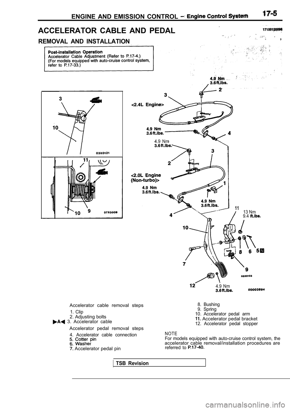
ACCELERATOR CABLE AND PEDAL
REMOVAL AND INSTALLATION ,
4.9 Nm
Accelerator cable removal steps
1. Clip
2. Adjusting bolts 3. Accelerator cableAccelerator pedal removal steps
4. Accelerator cable connection
Accelerator pedal pin
1113 Nm
9.4
4.9 Nm
8. Bushing
9. Spring
10. Accelerator pedal arm
Accelerator pedal bracket12. Accelerator pedal stopper
NOTEFor models equipped with auto-cruise control system , theaccelerator cable removal/installation procedures arereferred to
TSB Revision
Page 746 of 2103
17-6ENGINE ‘AND EMISSION Engine
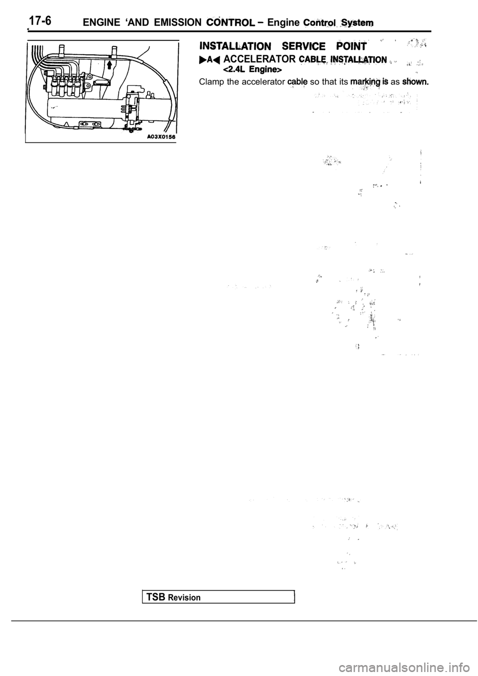
ACCELERATOR
Clamp the accelerator so that its as
I
TSBRevision
Page 747 of 2103
AND EMISSION CONTROL Auto-cruise Control System
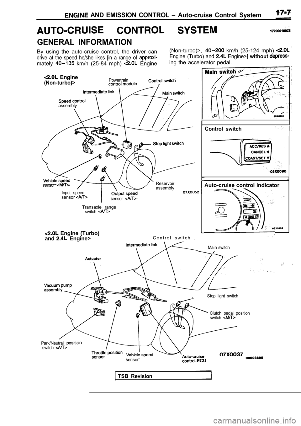
GENERAL INFORMATION
By using the auto-cruise control, the driver can
drive at the speed he/she likes [in a range of
mately km/h (25-84 mph) Engine
Engine
(Non-turbo)>Powertrain
(Non-turbo)>, km/h (25-124 mph)
Engine (Turbo) and Engine>] without
ing the accelerator pedal.
assemblv
sensor
Input speedsensorsensor
Control switch
Reservoirassembly
Transaxle rangeswitch
Engine (Turbo)
and
Engine> C o n t r o l s w i t c h ,.
Actuator
Auto-cruise control indicator
Main switch
,Stop light switch
Park/Neutralswitch
Clutch pedal position
switch
sensor
TSB Revision
Page 748 of 2103
E N G I N E A N D E M I S S I O N C O N T R O L .
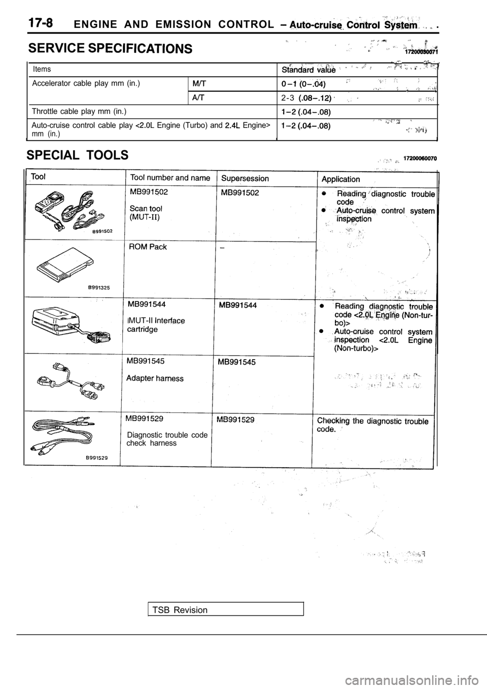
SERVICE
,
Items .
Accelerator cable play mm (in.)
2 - 3
Throttle cable play mm (in.)
Auto-cruise control cable play Engine (Turbo) and Engine>
mm (in.)
SPECIAL TOOLS
MUT-II
Diagnostic trouble code
check harness
TSB Revision
Page 749 of 2103
ENGINE AND EMISSION CONTROL Auto-cruise Control
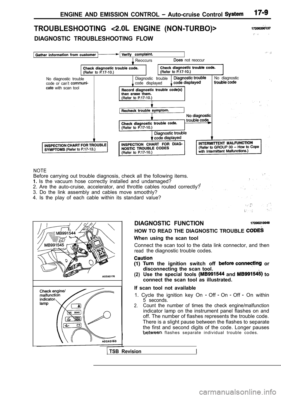
TROUBLESHOOTING ENGINE (NON-TURBO)>
DIAGNOSTIC TROUBLESHOOTING FLOW
Reoccurs not reoccur
No diagnostic troubleDiagnostic troubleNo diagnostic
code or can’t code displayed
with scan tool
NOTE
Before carrying out trouble diagnosis, check all th e following items.
Is the vacuum hose correctly installed and undamag ed?
2. Are the auto-cruise, accelerator, and throttle c ables routed correctly?
3. Do the link assembly and cables move smoothly?
4. Is the play of each cable within its standard va lue?
DIAGNOSTIC FUNCTION
HOW TO READ THE DIAGNOSTIC TROUBLE
When using the scan tool
Connect the scan tool to the data link connector, a nd then
readthe diagnostic trouble codes.
the ignition switch off or
disconnecting the scan tool.
(2)Use the special tools and to
connect the scan tool as illustrated.
If scan tool not available 1. Cycle the ignition key On
Off On Off On within
5 seconds.
2.Count the number of times the check engine/malfunct ion
indicator lamp on the instrument panel flashes on and
off. The number of flashes represents the trouble c ode.
There is a slight pause between the flashes to sepa rate
the first and second digits of the code. Longer pau ses
f l a s h e s s e p a r a t e i n d i v i d u a l t r o u b l e c o d e s .
TSB Revision
Page 750 of 2103
ENGINE AND EMISSION CONTROL Auto-cruise
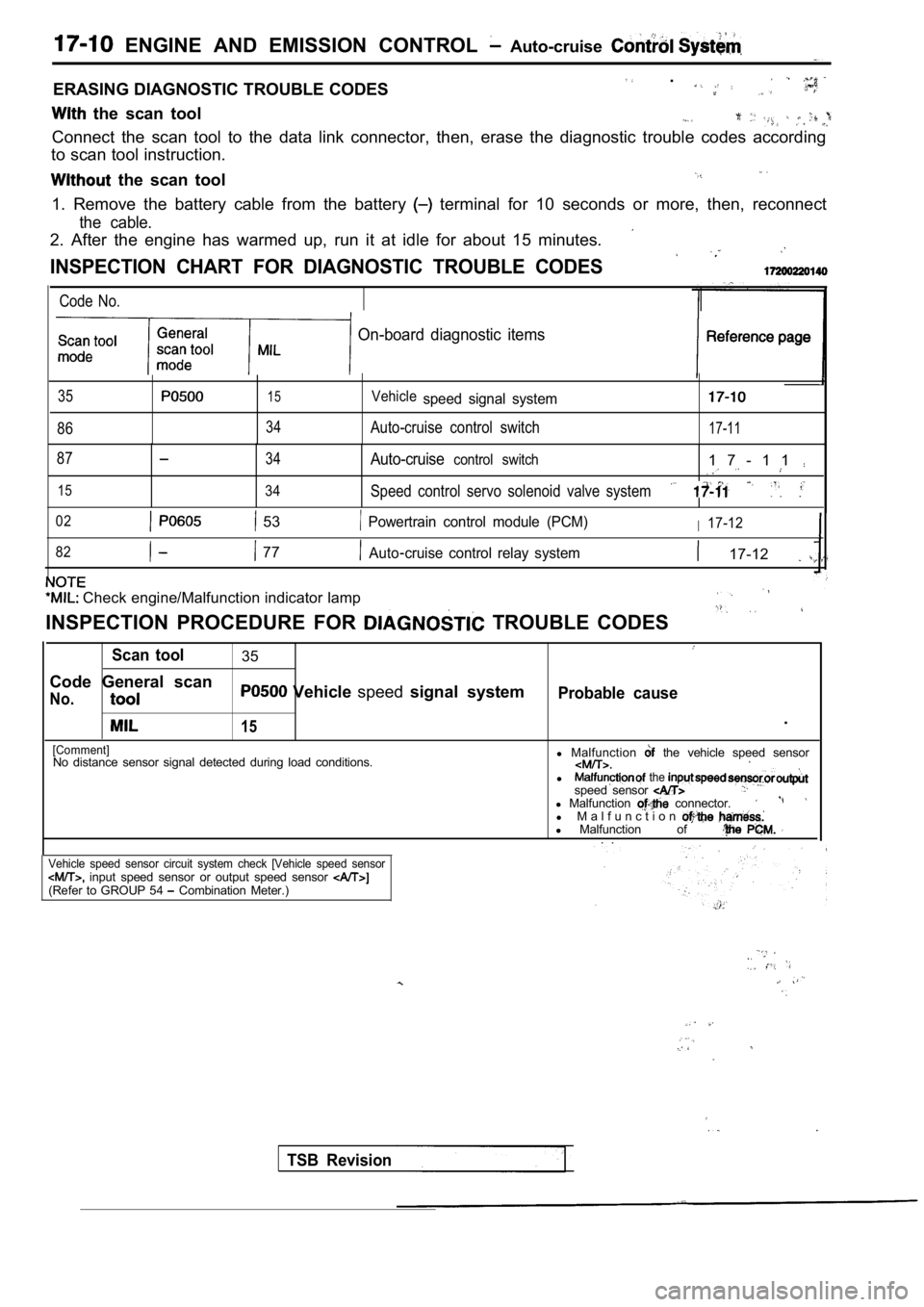
ERASING DIAGNOSTIC TROUBLE CODES .
the scan tool
Connect the scan tool to the data link connector, then, erase the diagnostic trouble codes according
to scan tool instruction.
the scan tool
1. Remove the battery cable from the battery terminal for 10 seconds or more, then, reconnect
the cable.
2. After the engine has warmed up, run it at idle f or about 15 minutes.
INSPECTION CHART FOR DIAGNOSTIC TROUBLE CODES
Code No.
On-board diagnostic items
35
86
15
34
Vehiclespeed signal system
Auto-cruise control switch17-11
87
15
34
34
Auto-cruisecontrol switch1 7 - 1 1
Speed control servo solenoid valve system
02 53 Powertrain control module (PCM)I17-12
82
77Auto cruise control relay system 17-12
Check engine/Malfunction indicator lamp
INSPECTION PROCEDURE FOR TROUBLE CODES
Scan tool35
Code General scan
No. Vehicle speedsignal systemProbable cause
15.
[Comment]No distance sensor signal detected during load cond itions.l
Malfunction the vehicle speed sensor
l the speed sensor l Malfunction connector.l M a l f u n c t i o nl Malfunction of . .
Vehicle speed sensor circuit system check [Vehicle speed sensor input speed sensor or output speed sensor (Refer to GROUP 54 Combination Meter.)
TSB Revision