MITSUBISHI SPYDER 1990 Service Repair Manual
Manufacturer: MITSUBISHI, Model Year: 1990, Model line: SPYDER, Model: MITSUBISHI SPYDER 1990Pages: 2103, PDF Size: 68.98 MB
Page 761 of 2103
![MITSUBISHI SPYDER 1990 Service Repair Manual ENGINE AND EMISSION CONTROL Auto-cruise Control’
Code 2 Vehicle speed signal system
[Comment]l Malfunction of the vehicle This diagnostic trouble code is output if the vehic le speed signa MITSUBISHI SPYDER 1990 Service Repair Manual ENGINE AND EMISSION CONTROL Auto-cruise Control’
Code 2 Vehicle speed signal system
[Comment]l Malfunction of the vehicle This diagnostic trouble code is output if the vehic le speed signa](/img/19/57345/w960_57345-760.png)
ENGINE AND EMISSION CONTROL Auto-cruise Control’
Code 2 Vehicle speed signal system
[Comment]l Malfunction of the vehicle This diagnostic trouble code is output if the vehic le speed signals from the vehicle speed sensor l of connectorare not input to the auto-cruise control-ECU when t he vehicle speed is 40 km/h (25 mph) l
Malfunction of the harness
or more. l Malfunction of the auto-cruise
Check the vehicle speed sen(Refer to GROUP 54 CombinationMeter.)
1. NG
Measure at the vehicle speed sensor connector Check the following connector. l Disconnect the connector, and measure at the
harness side.O K
1. Voltage between 1 and ground (Ignition switch: ON)
NG
System voltage
2.Voltage between 3 and ground2. N G(Ignition switch: ON)
OK: 4.6 5.2 3.Continuity between 2 and ground3. N G
OK: Continuity
OK
Check trouble symptom.
N G
Check the harness between the speed sensor
Check the following
OKNG
Check trouble symptom.
NG
Check the harness between the auto-cruise ECU and the vehicle soeed sensor connector.
OKNG
Replace the auto-cruise control-ECU.
and ignition switch connector
OK
Check the ignition switch.
(Refer to GROUP 54 , ,
Check the harness between the vehicle speed sensorand the ground. Repair, if necessary.
Code Autocruise vacuum pump power supply systemProbable cause
[Comment]
This code will be output when the drive signals for the auto-cruise vacuum pump release valve,
control valve and motor are not input to the auto-c ruise control-ECU.l
the stop light l
Malfunction of the connector
l
l of the auto-cruise
at the auto-cruise vacuum
l Disconnect the connector and
l Voltage between terminal (1) and
OKN G Check the harness between the cruise vacuum pump and the cruise control-ECU.
and
Replace the auto-cruise control-ECU.
TSB Revision
Page 762 of 2103
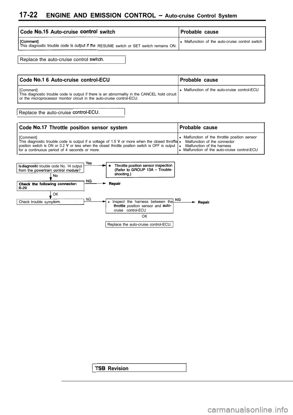
17-22ENGINE AND EMISSION CONTROL Auto-cruise Control System
Code Auto-cruise switch Probable cause
l Malfunction of the auto-cruise control switch
This diagnostic trouble code is output if the RESUME switch or SET switch remains ON.
Replace the auto-cruise control
Code 6 Auto-cruise control-ECU Probable cause
[Comment]l Malfunction of the auto-cruise control-ECU
This diagnostic trouble code is output if there is an abnormality in the CANCEL hold circuit
or the microprocessor monitor circuit in the auto-c ruise control-ECU.
Replace the auto-cruise
Code Throttle position sensor system Probable cause
[Comment]l
Malfunction of the throttle position sensor
This diagnostic trouble code is output if a voltage of 1.5 or more when the closed throffle l
Malfunction of the connectorposition switch is ON or 0.2 or less when the closed throttle position switch i s OFF is outputlMalfunction of the harness
for a continuous period of 4 seconds or more. l
Malfunction of the auto-cruise control-ECU
trouble code No. 14 outputfrom the powertrain control module?
OK
Check troubleNGsympl Inspect the harness between the position sensor and cruise control-ECU
OK
Revision
Replace the auto-cruise control-ECU.
Page 763 of 2103
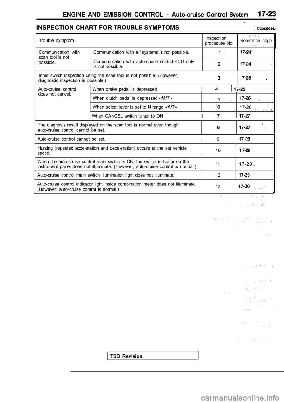
ENGINE AND EMISSION CONTROL Auto-cruise Control
INSPECTION CHART FOR SYMPTOMS
Communication with
scan tool is not
possible. Communication with systems is not possible.
Communication with auto-cruise control-ECU only
is not possible.1
2
Input switch inspection using the scan tool is not possible. (However,
diagnostic inspection is possible.)3 .
Auto-cruise control When brake pedal is depressed 4 does not cancel. When clutch pedal is depressed
When select lever is set to range
When CANCEL switch is set to ON
5
17-26
I 7 17-27
Trouble symptomInspection
procedure No.Reference page
The diagnosis result displayed on the scan tool is normal even though
auto-cruise control cannot be set.
Auto-cruise control cannot be set.I9
Hunting (repeated acceleration and deceleration) oc curs at the set vehicle
speed.I1
When the auto-cruise control main switch is ON, the switch indicator on the
instrument panel does not illuminate. (However, aut o-cruise control is normal.)
Auto-cruise control main switch illumination light does not illuminate.111 7 - 2 9 , .
1217-29
Auto-cruise control indicator light inside combinat ion meter does not illuminate.
(However, auto-cruise control is normal.)13
TSB Revision
Page 764 of 2103
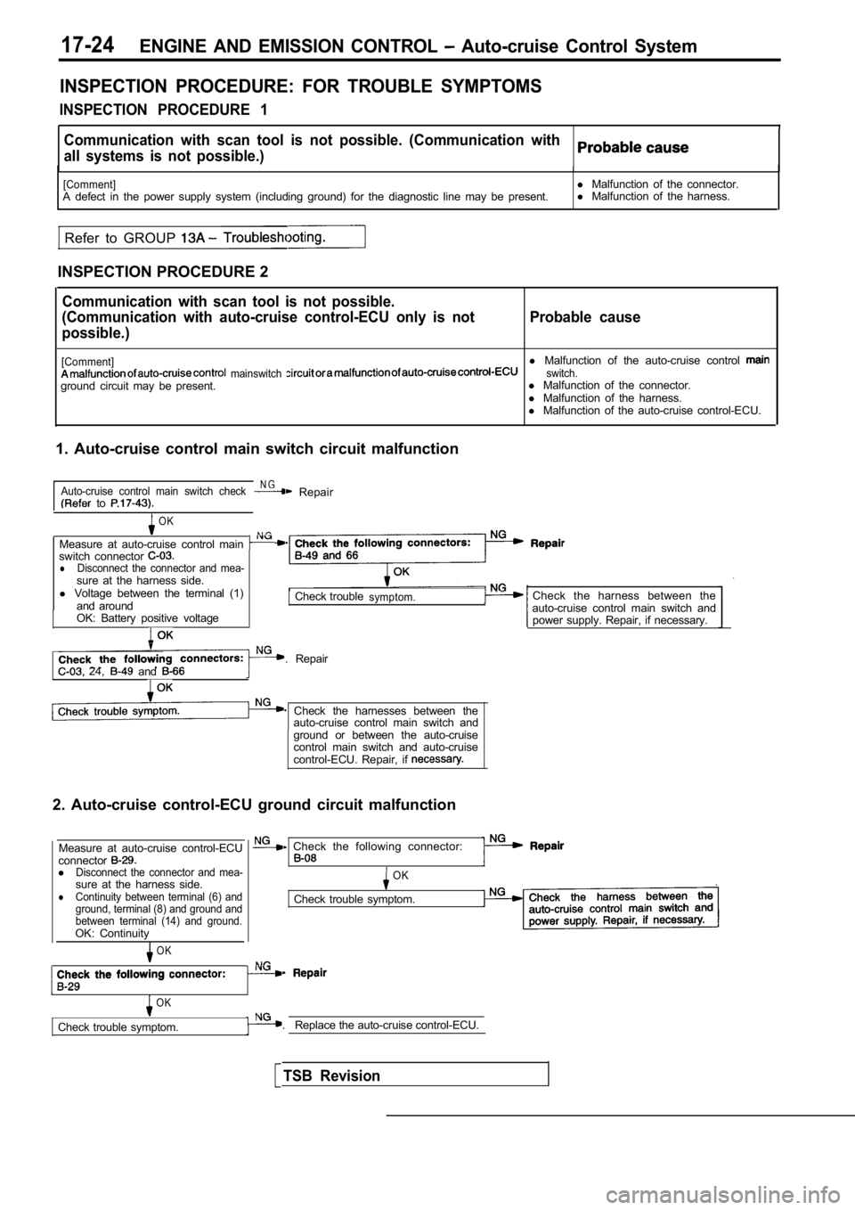
17-24ENGINE AND EMISSION CONTROL Auto-cruise Control System
INSPECTION PROCEDURE: FOR TROUBLE SYMPTOMS
INSPECTION PROCEDURE 1
Communication with scan tool is not possible. (Comm unication with
all systems is not possible.)
[Comment]A defect in the power supply system (including grou nd) for the diagnostic line may be present.
Refer to GROUP
INSPECTION PROCEDURE 2 l
Malfunction of the connector.
l Malfunction of the harness.
Communication with scan tool is not possible.
(Communication with auto-cruise control-ECU only is not
possible.) Probable cause
[Comment]l
Malfunction of the auto-cruise control mainswitch switch.ground circuit may be present. l
Malfunction of the connector.
l Malfunction of the harness.
l Malfunction of the auto-cruise control-ECU.
1. Auto-cruise control main switch circuit malfunct ion
Auto-cruise control main switch checkN G Repair to
OK
N G Measure at auto-cruise control main switch connector lDisconnect the connector and mea-sure at the harness side.
l Voltage between the terminal (1)
and around
OK: Battery positive voltage
Check troublesymptom.
. Repair 24, and
Check the harnesses between the auto-cruise control main switch and
ground or between the auto-cruise
control main switch and auto-cruise
control-ECU. Repair, if
2. Auto-cruise control-ECU ground circuit malfuncti on
Measure at auto-cruise control-ECU
connector
lDisconnect the connector and mea-sure at the harness side.lContinuity between terminal (6) and
ground, terminal (8) and ground and
between terminal (14) and ground.
OK: Continuity
OK
Check the harness between the
auto-cruise control main switch and power supply. Repair, if necessary.
Check the following connector:
OK
Check trouble symptom.
OK
Check trouble symptom. . Replace the auto-cruise control-ECU.
TSB Revision
Page 765 of 2103
![MITSUBISHI SPYDER 1990 Service Repair Manual ENGINE AND EMISSION System
.,
INSPECTION PROCEDURE 3
Input switch inspection using the scan tool is pdssible.
(However, diagnostic inspection is possible.)
I
[Comment]A malfunction MITSUBISHI SPYDER 1990 Service Repair Manual ENGINE AND EMISSION System
.,
INSPECTION PROCEDURE 3
Input switch inspection using the scan tool is pdssible.
(However, diagnostic inspection is possible.)
I
[Comment]A malfunction](/img/19/57345/w960_57345-764.png)
ENGINE AND EMISSION System
.,
INSPECTION PROCEDURE 3
Input switch inspection using the scan tool is pdssible.
(However, diagnostic inspection is possible.)
I
[Comment]A malfunction of auto-cruise control switch circuit system may be present.l
Malfunction of the auto-cruise control l Malfunction of the clock spring .
l of the connector.
l Malfunction of the harness.
.
NG
(Refer to
Measure at clock spring connector
l sure at the harness side
l Voltage between terminal (2) and
groundOK: Battery positive voltage
OK
Check trouble symptom.
C h e c k t r o u b l e spring and auto-cruise
INSPECTION PROCEDURE 4
When brake pedal is depressed, auto-cruise control does not
cancel.Probable , ,
[Comment]A malfunction of stop light switch or a malfunction of stop light circuit may be present.l
Malfunction of the stop light switch.
l Malfunction of the connector.
l Malfunction of. the
l Malfunction of the auto-cruise control-ECU.
Does stop
illuminate?
No
Replace the auto-cruise control-ECU.
lDisconnect the connector and mea-sure at the harness side.
Check trouble symptom.Check the following connectors:
TSB Revision
Page 766 of 2103
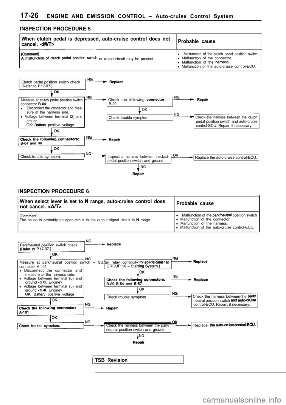
17-26E N G I N E A N D E M I S S I O N C O N T R O L Auto-cruise Control System
INSPECTION PROCEDURE 5
When clutch pedal is depressed, auto-cruise control does not
cancel.Probable cause
or clutch circuit may be present. l
Malfunction of the clutch pedal position switch.l
Malfunction of the connector.
l Malfunction of the
l Malfunction of the auto-cruise control-ECU.
Clutch pedal position switch check
(Refer to
Measure at clutch pedal position switchconnectorlDisconnect the connector and mea-sure at the harness side.
l Voltage between terminal (2) and
groundOK: positive voltage
Check the following
OK.Check trouble symptom.NG Check the harness between the clutchpedal position switch and auto-cruise
control-ECU. Repair, if necessary.
Check trouble symptom.Inspectthe harness between theclutchpedal position switch and ground.
NG
Replace the auto-cruise control-ECU.
INSPECTION PROCEDURE 6
When select lever is set to range, auto-cruise control does
not cancel. Probable cause
[Comment]The cause is probably an open-circuit in the output signal circuit in range.l
Malfunction of the position switch
l Malfunction of the connector.
l Malfunction of the harness.
l Malfunction of the auto-cruise control-ECU.
Park/neutral position switch check
Measure at park/neutral position switch -- Starter relay continuity check (Refer to check (Refer toconnector A-l 01.GROUP 16 Starting System.)
ing System.)
l Disconnect the connector and
measure at the harness side.OK
l Voltage between terminal (6) andNG
ground Engine>l Voltage between terminal (5) and and
ground Engine>OK
OK: Battery positive voltage
Check trouble symptom. Check the harness between-the neutral position switch control-ECU. Repair, if necessary.
Check the harness between the park/ Replace control-ECU.,.neutral position switch and ground.
neutral position switch and ground.,
NGNG
TSB Revision
Page 767 of 2103
![MITSUBISHI SPYDER 1990 Service Repair Manual ENGINE AND EMISSION CONTROL Control. System
INSPECTION PROCEDURE 7
When auto-cruise control CANCEL switch is set to ON,
auto-cruise control does not cancel.
[Comment]An open-circu MITSUBISHI SPYDER 1990 Service Repair Manual ENGINE AND EMISSION CONTROL Control. System
INSPECTION PROCEDURE 7
When auto-cruise control CANCEL switch is set to ON,
auto-cruise control does not cancel.
[Comment]An open-circu](/img/19/57345/w960_57345-766.png)
ENGINE AND EMISSION CONTROL Control. System
INSPECTION PROCEDURE 7
When auto-cruise control CANCEL switch is set to ON,
auto-cruise control does not cancel.
[Comment]An open-circuit in the circuit inside the CANCEL sw itch may be present.
Replace the auto-cruise control switch.
INSPECTION PROCEDURE 8l the
The diagnostic result displayed on the scan tool is normal
even though auto-cruise control cannot be set.
[Comment]Because of an open-circuit in the battery backup ci rcuit system, the fail-safe function preventsdiagnostic trouble codes from being memorized and d isplayed even though auto-cruise controlis canceled.
Probable cause
l Malfunction of the connector.
l Malfunction the harness.
l Malfunction of the
Measure at auto-cruise control-ECU
connector
l sure at the harness side.lVoltage between terminal (16) and
around
Battery positive voltage
OKCheck the harness between the
auto-cruise control-ECU and power
supply. Repair, if necessary.
Check the following connector:
Replace the auto-cruise control-ECU.
TSB Revision
Page 768 of 2103
![MITSUBISHI SPYDER 1990 Service Repair Manual 17-28ENGINE AND CONTROL Auto-cruise Control System
INSPECTION PROCEDURE 9
Auto-cruise control cannot be set. c a u s e
[Comment] Malfunction of the auto-cruise control main
A malfun MITSUBISHI SPYDER 1990 Service Repair Manual 17-28ENGINE AND CONTROL Auto-cruise Control System
INSPECTION PROCEDURE 9
Auto-cruise control cannot be set. c a u s e
[Comment] Malfunction of the auto-cruise control main
A malfun](/img/19/57345/w960_57345-767.png)
17-28ENGINE AND CONTROL Auto-cruise Control System
INSPECTION PROCEDURE 9
Auto-cruise control cannot be set. c a u s e
[Comment] Malfunction of the auto-cruise control main
A malfunction of switches or that the fail-safe fun ction auto-cruise control may beswitch.
present.lMalfunction of the auto-cruise control l Malfunction of the clock l Malfunction of the harnesses or connectors.l of the clutch pedal position switch
lMalfunction of the park/neutral position switch
l Malfunction of control-EC@
Can the auto-cruise control communicate with the sc an
NoInspection for each trouble symptom.(Refer to inspection procedure No. 2 on
Yes
Is input switch inspection possible with the scan tool?
Yes
Inspectionfor trouble symptom.
(Refer to inspection procedure No. 3 on
Dose the input switch code or 27 remain output? Yes
No
Dose the input switch code or 26
No
Replace the auto-cruise control-ECU.
Yes lStop(Refer to inspection procedure No. 14 on lClutch pedal position switch or tion switch input circuit system [code
INSPECTION PROCEDURE 10
Hunting (repeated acceleration deceleration) occurs at the
set vehicle speed.
l Malfunction of the vehicle speed sensor.
A malfunction of vehicle speed sensor or incorrect vacuum in the auto-cruise vacuum pumplMalfunction of the auto-cruise l Malfunctionl Malfunction of the auto-cruise control-ECU.
Revision
Auto-cruise vacuum pump check (Refer to NG Replace
Actuator check (Refer to
Page 769 of 2103
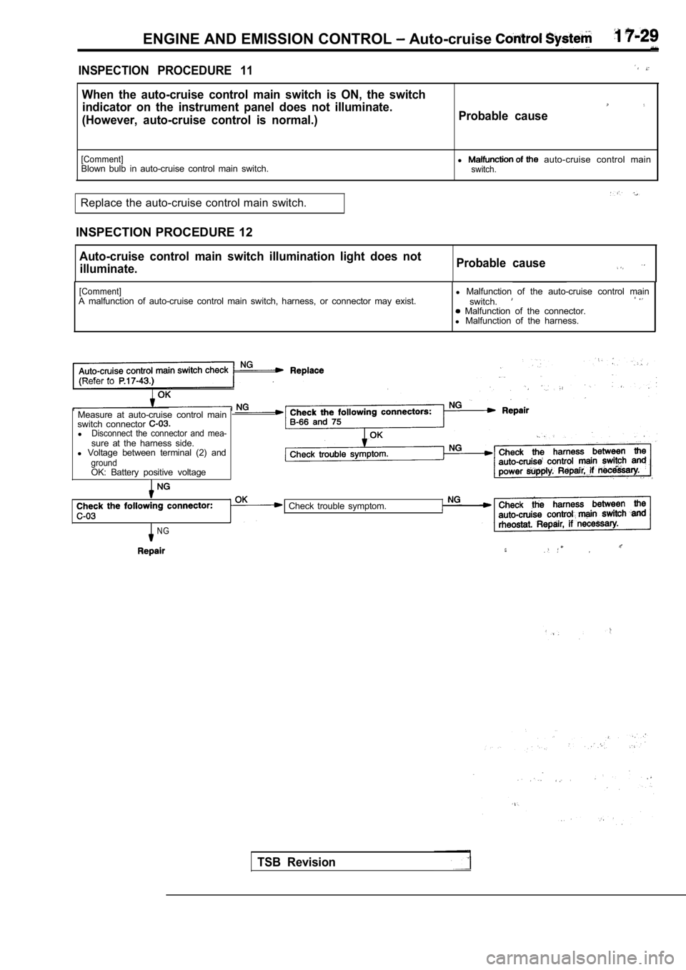
ENGINE AND EMISSION CONTROL Auto-cruise
INSPECTION PROCEDURE 11
When the auto-cruise control main switch is ON, the switch
indicator on the instrument panel does not illumina te.
(However, auto-cruise control is normal.) Probable cause
[Comment]l auto-cruise control main
Blown bulb in auto-cruise control main switch.switch.
Replace the auto-cruise control main switch.
INSPECTION PROCEDURE 12
Auto-cruise control main switch illumination light does not
illuminate. Probable cause
[Comment]A malfunction of auto-cruise control main switch, h
arness, or connector may exist.l
Malfunction of the auto-cruise control main
switch. Malfunction of the connector.
l Malfunction of the harness.
(Refer to
Measure at auto-cruise control main
switch connector
lDisconnect the connector and mea-sure at the harness side.
l Voltage between terminal (2) and
groundOK: Battery positive voltage
NG
Check trouble symptom.
TSB Revision
Page 770 of 2103
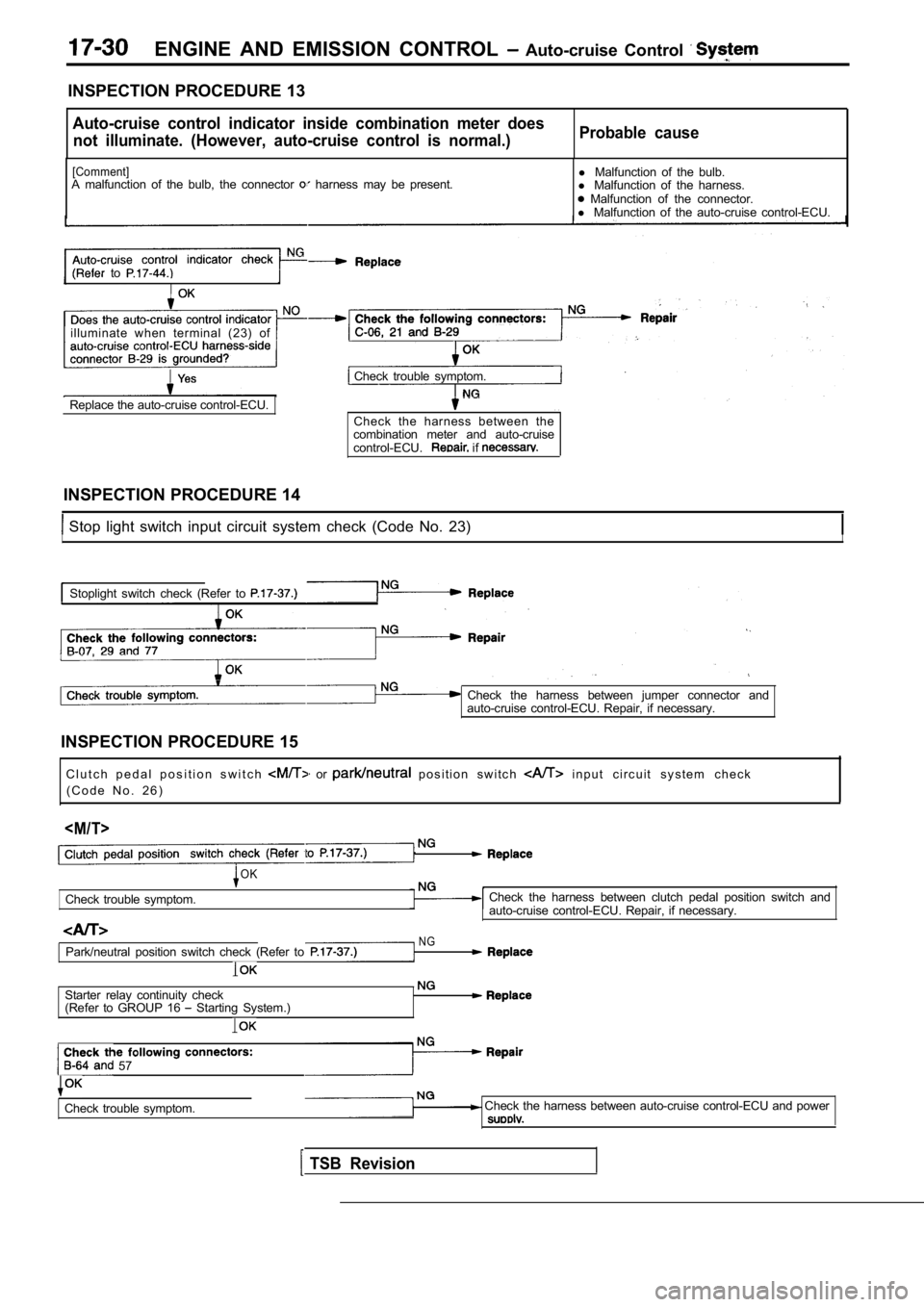
ENGINE AND EMISSION CONTROL Auto-cruise Control
INSPECTION PROCEDURE 13
Auto-cruise control indicator inside combination meter does
not illuminate. (However, auto-cruise control is no rmal.)Probable cause
[Comment]A malfunction of the bulb, the connector harness may be present. l
Malfunction of the bulb.
l Malfunction of the harness. Malfunction of the connector.
l Malfunction of the auto-cruise control-ECU.
to
illuminate when terminal (23) of
Check trouble symptom.
Replace the auto-cruise control-ECU. Check the harness between the
combination meter and auto-cruise
control-ECU.
if
INSPECTION PROCEDURE 14
Stop light switch input circuit system check (Code No. 23)II
Stoplight switch check (Refer to
Check the harness between jumper connector and
auto-cruise control-ECU. Repair, if necessary.
INSPECTION PROCEDURE 15 C l u t c h p e d a l p o s i t i o n s w i t c h
or p o s i t i o n s w i t c h i n p u t c i r c u i t s y s t e m c h e c k
( C o d e N o . 2 6 )
Check trouble symptom.
OK
NG
Check the harness between clutch pedal position swi tch and
auto-cruise control-ECU. Repair, if necessary.
Park/neutral position switch check (Refer to
Starter relay continuity check
(Refer to GROUP 16 Starting System.)
57
Check trouble symptom. Check the harness between auto-cruise control-ECU and power
TSB Revision