tires MITSUBISHI SPYDER 1990 Service Repair Manual
[x] Cancel search | Manufacturer: MITSUBISHI, Model Year: 1990, Model line: SPYDER, Model: MITSUBISHI SPYDER 1990Pages: 2103, PDF Size: 68.98 MB
Page 1548 of 2103
REAR AXLE Troubleshooting
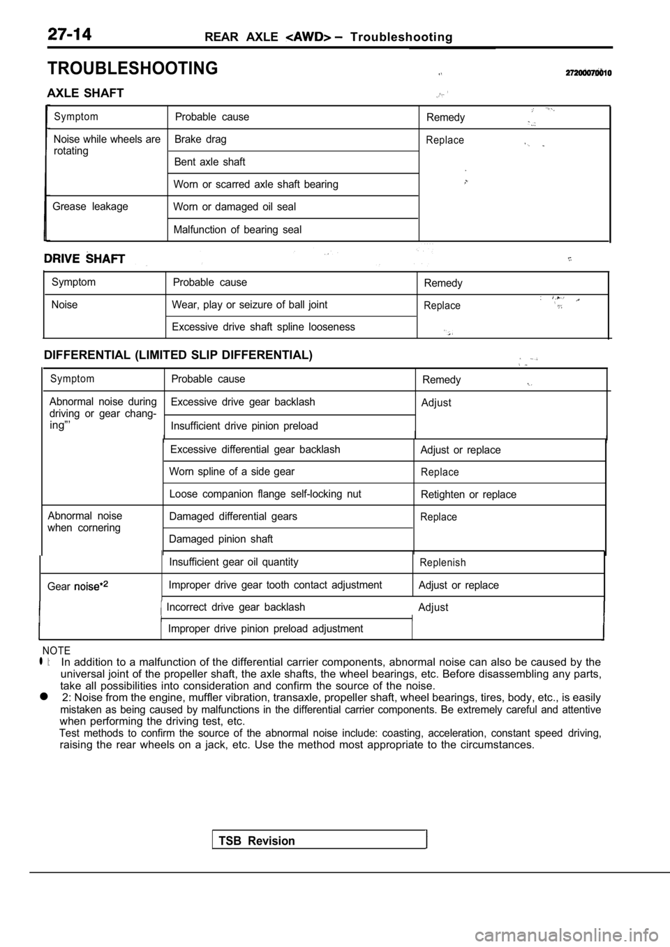
TROUBLESHOOTING
AXLE SHAFT
SymptomProbable causeRemedy
Noise while wheels are Brake drag
rotatingReplace
Bent axle shaft
Worn or scarred axle shaft bearing
Grease leakage Worn or damaged oil seal
Malfunction of bearing seal
Symptom
Noise Probable cause
Wear, play or seizure of ball joint Remedy
Replace
Excessive drive shaft spline looseness
DIFFERENTIAL (LIMITED SLIP DIFFERENTIAL)
SymptomProbable cause
Remedy
Abnormal noise during
driving or gear chang-Excessive drive gear backlash
Adjust
ing”’Insufficient drive pinion preload
II II
Abnormal noise
when cornering Excessive differential gear backlash
Worn spline of a side gear
Loose companion flange self-locking nut
Damaged differential gears
Damaged pinion shaft Adjust or replace
Replace
Retighten or replace
Replace
TSB Revision
Gear
Insufficient gear oil quantity
Improper drive gear tooth contact adjustmentReplenish
Adjust or replace
Incorrect drive gear backlash Adjust
I II
IImproper drive pinion preload adjustment
NOTE
l l:In addition to a malfunction of the differential carrier components, abnormal noise can also be caused by the
universal joint of the propeller shaft, the axle sh afts, the wheel bearings, etc. Before disassembling any parts,
take all possibilities into consideration and confi rm the source of the noise.
l 2: Noise from the engine, muffler vibration, transa xle, propeller shaft, wheel bearings, tires, body, etc., is easily
mistaken as being caused by malfunctions in the dif ferential carrier components. Be extremely careful and attentive
when performing the driving test, etc.
Test methods to confirm the source of the abnormal noise include: coasting, acceleration, constant speed
raising the rear wheels on a jack, etc. Use the met hod most appropriate to the circumstances.
driving,
Page 1549 of 2103
R E A R
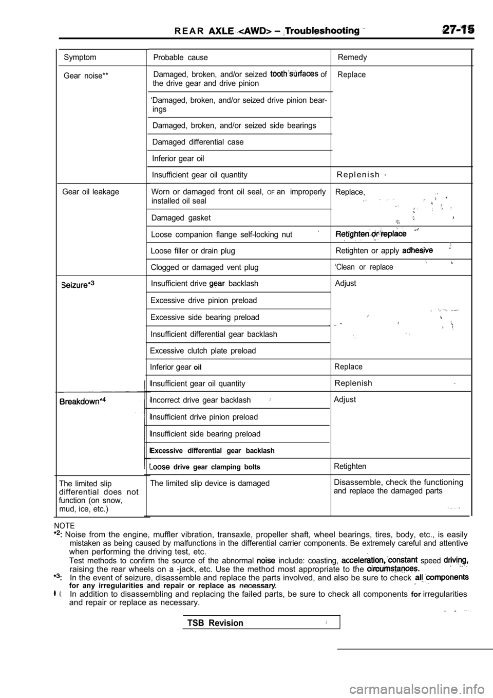
Symptom
Gear noise**
Gear oil leakage
The limited slip
differential does not
function (on snow, mud, ice, etc.)
NOTE
Noise from the engine, muffler vibration, transaxl e, propeller shaft, wheel bearings, tires, body, etc., is easily
mistaken as being caused by malfunctions in the dif ferential carrier components. Be extremely careful and attentive
when performing the driving test, etc.
Test methods to confirm the source of the abnormal include: coasting, speed
raising the rear wheels on a -jack, etc. Use the me thod most appropriate to the
In the event of seizure, disassemble and replace the parts involved, and also be sure to check for any irregularities and repair or replace as
l 4:In addition to disassembling and replacing the failed parts, be sure to check all components forirregularities
and repair or replace as necessary.
Probable cause Remedy
Damaged, broken, and/or seized
ofReplace
the drive gear and drive pinion
‘Damaged, broken, and/or seized drive pinion bear- ings
Damaged, broken, and/or seized side bearings
Damaged differential case
Inferior gear oil
Insufficient gear oil quantity
R e p l e n i s h
Worn or damaged front oil seal, OFan improperly Replace,
installed oil seal
Damaged gasket
Loose companion flange self-locking nut
Loose filler or drain plug Retighten or apply
‘Clean or replaceClogged or damaged vent plug
Insufficient drive
backlash
Excessive drive pinion preload
Excessive side bearing preload
Insufficient differential gear backlash
Excessive clutch plate preload
Inferior gear
oil
Insufficient gear oil quantity
Incorrect drive gear backlash
Insufficient drive pinion preload
Insufficient side bearing preload
Excessive differential gear backlash
drive gear clamping bolts
The limited slip device is damaged Adjust
Replace
Replenish
Adjust
Retighten
Disassemble, check the functioning
and replace the damaged parts
TSB Revision
Page 1588 of 2103
WHEEL AND TIRE
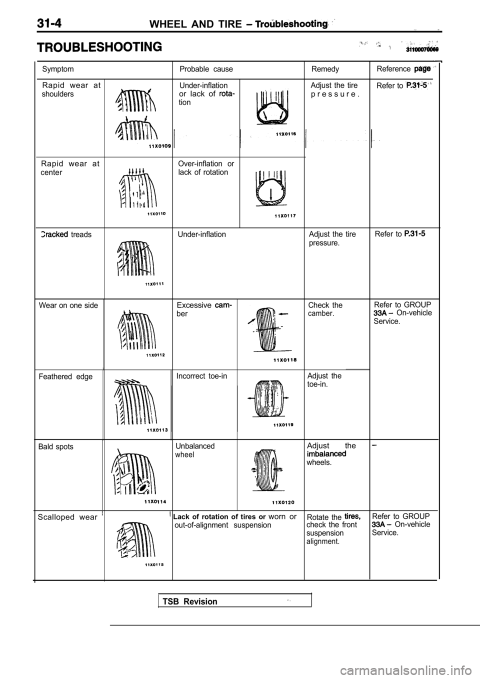
Symptom
Rapid wear at
shouldersProbable cause
Under-inflationor lack of
tion
Remedy Reference
Adjust the tire
Refer to
p r e s s u r e .
Rapid wear at
Over-inflation or
center
lack of rotation
I
treads Under-inflation Adjust the tireRefer to
pressure.
Wear on one side
Excessive
ber Check thecamber.
Refer to GROUP On-vehicle
Service.
Feathered edge Incorrect toe-in
Adjust the
toe-in.
Bald spots Unbalanced
wheel
Adjust the
wheels.
Scalloped wear Lack of rotation of tires or
worn orRotate the Refer to GROUP
out-of-alignment suspension check the front On-vehicle
suspension Service.
alignment.
TSB Revision
Page 1589 of 2103
WHEEL AND TIRE On-vehicle Service/Wheel and Tire
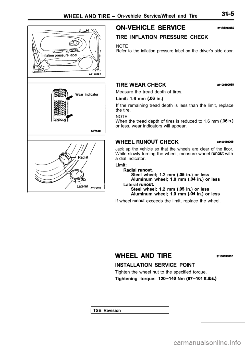
Wear indicator
TIRE INFLATION PRESSURE CHECK
NOTERefer to the inflation pressure label on the driver ’s side door.
TIRE WEAR CHECK
Measure the tread depth of tires.
Limit: 1.6 mm
in.)
If the remaining tread depth is less than the limit , replace
the tire.
NOTE
When the tread depth of tires is reduced to 1.6 mm
or less, wear indicators will appear.
WHEEL
CHECK
Jack up the vehicle so that the wheels are clear of the floor.
While slowly turning the wheel, measure wheel with
a dial indicator.
Limit:
Radial
Steel wheel; 1.2 mm in.) or less
Aluminum wheel; 1.0 mm
in.) or less
Lateral
Steel wheel; 1.2 mm in.) or less
Aluminum wheel; 1.0 mm
in.) or less
If wheel
exceeds the limit, replace the wheel.
INSTALLATION SERVICE POINT
Tighten the wheel nut to the specified torque.
Tightening torque:
Nm
TSB Revision
Page 1602 of 2103
FRONT SUSPENSION General Information
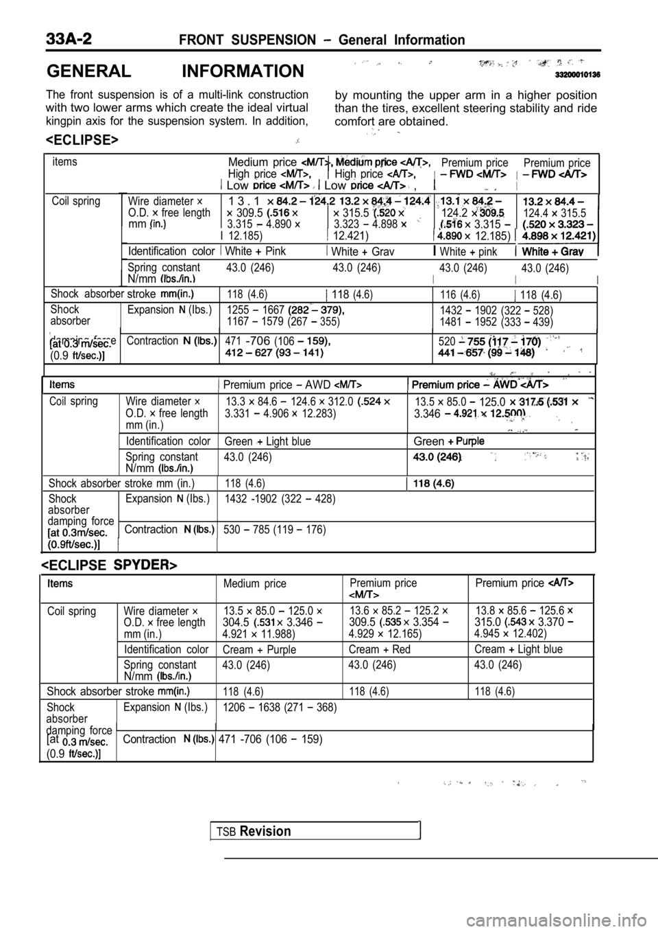
GENERAL INFORMATION
The front suspension is of a multi-link constructionby mounting the upper arm in a higher position
with two lower arms which create the ideal virtual than the tires, excellent steering stability and ride
kingpin axis for the suspension system. In addition ,comfort are obtained.
itemsMedium price
High price
Premium price
I
Premium priceHigh price I Low Low ,I
Coil spring
Wire diameter
O.D. free length
1 3 . 1
309.5 315.5 mm3.315 4.890 3.323 4.898
124.2
3.315
I 12.185) 12.421) 12.185)
Identification color White Pink White GravIWhite pink
124.4 315.5
Spring constant 43.0 (246) 43.0 (246)
I
43.0 (246)N/mmI
43.0 (246)
I
Shock absorberstroke118 (4.6) 118(4.6)116 (4.6) 118 (4.6)
Shock Expansion
(Ibs.)1255 16671432 1902(322 528)
absorber 1167 1579(267355)1481 1952 (333 439)
damping force
Contraction471-706(106520
(0.9
Premium price AWD
Coilspring Wire diameter 13.3 84.6 124.6 312.013.5 85.0 125.0
O.D. free length 3.331 4.906 12.283)3.346
mm (in.)
Identification color Green Light blueGreen
Spring constant43.0 (246)
N/mm
Shock absorber stroke mm (in.)118 (4.6)
ShockExpansion (Ibs.)
1432 -1902 (322 428)
absorber
damping force
Contraction530 785 (119 176)
Medium price Premium pricePremium price
Coil spring Wire diameter 13.5 85.0 125.0 13.6 85.2 125.2 13.8 85.6 125.6
O.D. free length304.5 3.346 309.5 3.354 315.0 3.370
mm (in.) 4.921 11.988)
4.929 12.165)4.945 12.402)
Identification color Cream
PurpleCream RedCream Light blue
Spring constant 43.0 (246) 43.0 (246) 43.0 (246)
N/mm
Shock absorber stroke 118 (4.6) 118 (4.6) 118 (4.6)
ShockExpansion (Ibs.)
1206 1638 (271 368)
absorber
damping force
[atContraction 471 -706 (106 159)
(0.9
Page 1604 of 2103
FRONT __
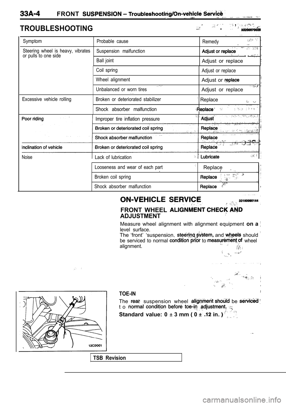
TROUBLESHOOTING
, .
SymptomProbable cause
Remedy
Steering wheel is heavy, vibratesSuspension malfunction
or pulls to one side, ,
Ball jointAdjust or replace
Coil spring
Wheel alignment
Unbalanced or worn tires Adjust or replace
Adjust or
Adjust or replace
Excessive vehicle rollingBroken or deteriorated stabilizer
Shock absorber malfunction
Replace
Improper tire inflation pressure
NoiseLack of lubrication
Looseness and wear of each part
.
Broken coil spring
Shock absorber malfunction
Replace
FRONT WHEEL
ADJUSTMENT
Measure wheel alignment with alignment equipment on a
level surface.
The ‘front’ ‘suspension, and should
be serviced to normal to wheel
alignment.
TOE-IN
The suspension wheel be
t o
Standard value: 0 3 mm 0 in.
TSB Revision
Page 1692 of 2103
ABS
TROUBLESHOOTING
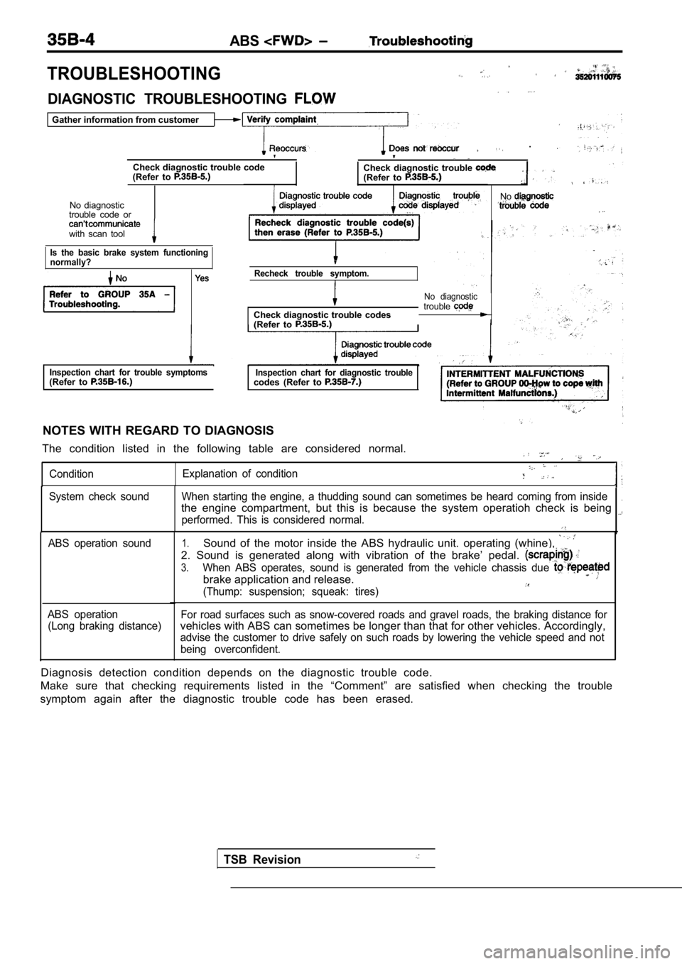
DIAGNOSTIC TROUBLESHOOTING
Gather information from customer
.
Check diagnostic trouble code
(Refer to Check diagnostic trouble (Refer to
No diagnostic
trouble code or
with scan tool
Is the basic brake system functioning
normally?
Recheck trouble symptom.
Check diagnostic trouble codes
(Refer to
No diagnostictrouble
Inspection chart for trouble symptoms(Refer to Inspection chart for diagnostic troublecodes (Refer to
NOTES WITH REGARD TO DIAGNOSIS
The condition listed in the following table are con sidered normal.
ConditionExplanation of condition
No
.
TSB Revision
System check sound When starting the engine, a thudd
ing sound can sometimes be heard coming from inside.the engine compartment, but this is because the system operatioh check is being
performed. This is considered normal.
ABS operation sound
ABS operation (Long braking distance)1.Sound of the motor inside the ABS hydraulic unit. o perating (whine),
2. Sound is generated along with vibration of the b rake’ pedal.
3.When ABS operates, sound is generated from the vehi cle chassis due
brake application and release.
(Thump: suspension; squeak: tires)
For road surfaces such as snow-covered roads and gravel roads, the braking distance forvehicles with ABS can sometimes be longer than that for other vehicles. Accordingly,
advise the customer to drive safely on such roads by lowering the vehicle speed and not
being overconfident.
Diagnosis detection condition depends on the diagno stic trouble code.
Make sure that checking requirements listed in the “Comment” are satisfied when checking the trouble
symptom again after the diagnostic trouble code has been erased.
Page 1734 of 2103
ABS
TROUBLESHOOTING
Check diagnostic trouble codeC h e c k d i a g n o s t i c t r o u b l e c o d e to to
No diagnostic troubleDiagnostic trouble codecode or can’t Diagnostic trouble
displayed c o d e
nicate with scan tool Recheck diagnostic trouble code(s)
then erase (Refer to
No diagnostic trouble
code
.
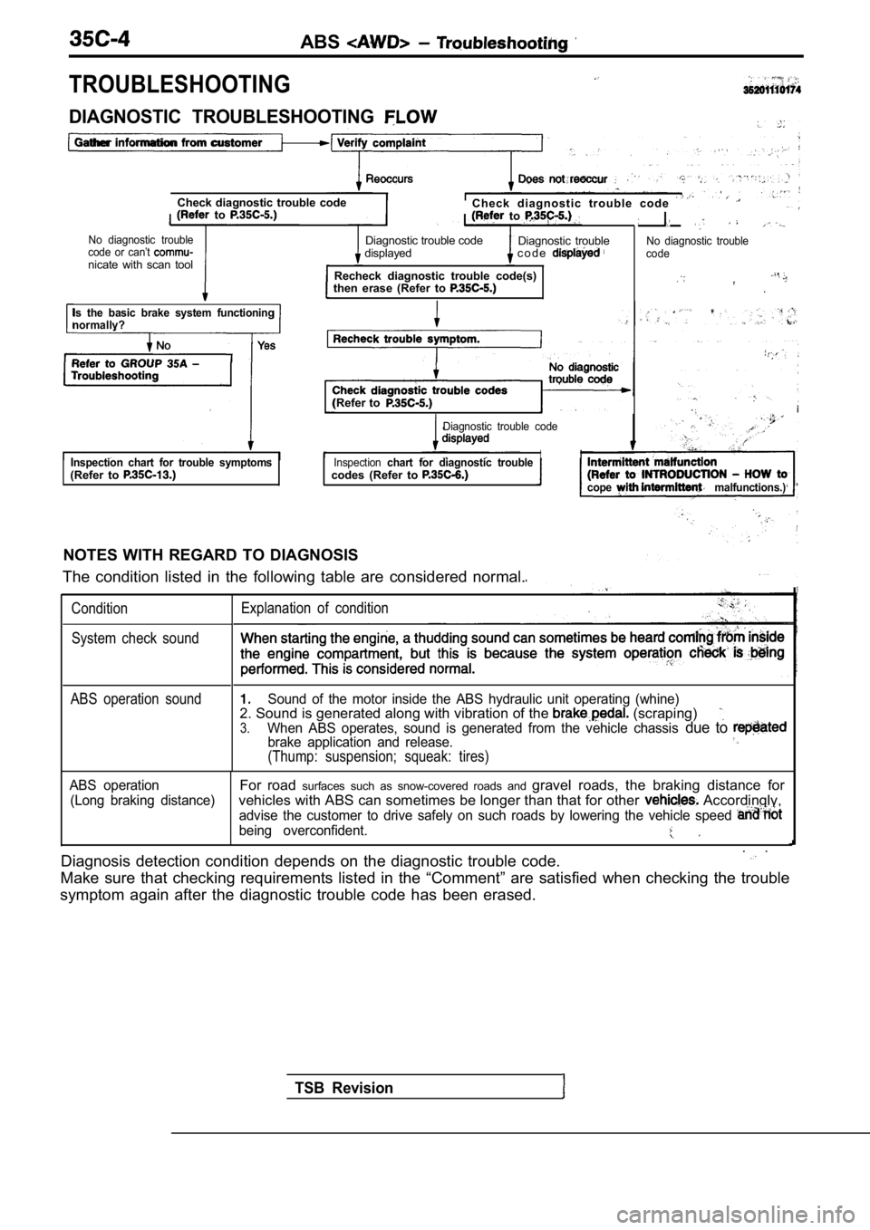
DIAGNOSTIC TROUBLESHOOTING
Gather information from customer
Is the basic brake system functioning
normallv?
(Refer to
Diagnostic trouble code
Inspection chart for trouble symptoms(Refer to Inspectionchart for diagnostic troubleII
codes (Refer to
cope malfunctions.)
NOTES WITH REGARD TO DIAGNOSIS
The condition listed in the following table are con sidered normal.
ConditionExplanation of condition
System check sound
TSB Revision
ABS operation soundSound of the motor inside the ABS hydraulic unit op erating (whine)2. Sound is generated along with vibration of the (scraping)
3.When ABS operates, sound is generated from the vehi cle chassis due to brake application and release.
(Thump: suspension; squeak: tires)
ABS operationFor road surfaces such as snow-covered roads and gravel roads, the braking distance for
(Long braking distance)vehicles with ABS can sometimes be longer than that for other Accordingly,
advise the customer to drive safely on such roads by lowering the vehicle speed
being overconfident.
. .
Diagnosis detection condition depends on the diagno stic trouble code.
Make sure that checking requirements listed in the “Comment” are satisfied when checking the trouble
symptom again after the diagnostic trouble code has been erased.
Page 2039 of 2103
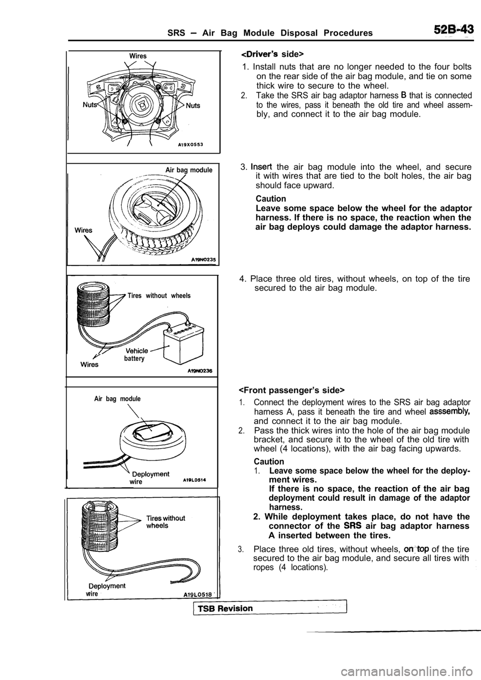
SRS Air Bag Module Disposal Procedures
Wires
Air bag module
Tires without wheels
battery
Air bag module
wire
side>
1. Install nuts that are no longer needed to the fo ur bolts
on the rear side of the air bag module, and tie on some
thick wire to secure to the wheel.
2.Take the SRS air bag adaptor harness that is connected
to the wires, pass it beneath the old tire and whee l assem-
bly, and connect it to the air bag module.
3.
the air bag module into the wheel, and secure
it with wires that are tied to the bolt holes, the air bag
should face upward.
Caution
Leave some space below the wheel for the adaptor
harness. If there is no space, the reaction when th e
air bag deploys could damage the adaptor harness.
4. Place three old tires, without wheels, on top of the tire
secured to the air bag module.
1.Connect the deployment wires to the SRS air bag ada ptor
harness A, pass it beneath the tire and wheel
and connect it to the air bag module.
2.Pass the thick wires into the hole of the air bag m odule
bracket, and secure it to the wheel of the old tire with
wheel (4 locations), with the air bag facing upward s.
Caution
1.Leave some space below the wheel for the deploy-
ment wires.
If there is no space, the reaction of the air bag
deployment could result in damage of the adaptor
harness.
2. While deployment takes place, do not have the connector of the
air bag adaptor harness
A inserted between the tires.
3.Place three old tires, without wheels, of the tire
secured to the air bag module, and secure all tires with
ropes (4 locations).
wire