CHARGING SYSTEM -Alternator-
Reasi
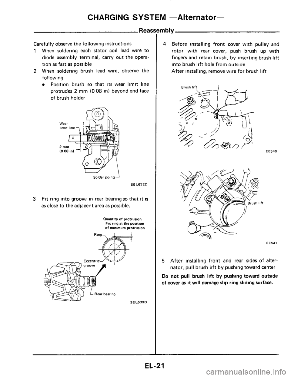
Carefully observe the following instructions
1 When soldering each stator coil lead wire to
diode assembly terminal, carry out the opera-
tion
as fast as possible
2 When soldering brush lead wire, observe the
following
Position brush so that its wear limit line
protrudes 2 mm (0 08 in) beyond end face
of brush holder
Solder points
SEL6320
3 Fit ring into groove in rear bearing so that it is
as close to the adjacent area as possible.
Quantity of prorrusion FIX ring at the position of minimum protrusion
mbly
4 Before installing front cover with pulley and
rotor with
rear cover, push brush up with
fingers and retain brush, by inserting brush
lift
into brush lift hole from outside
After installing, remove wire for brush
lift
EE540
EE541
5 After installing front and rear sides of alter-
nator, pull brush lift by pushing toward center
Do not pull brush lift by pushing toward outside
of cover as it will damage slip ring sliding surface.
EL-21
CHARGING SYSTEM -Alternator-
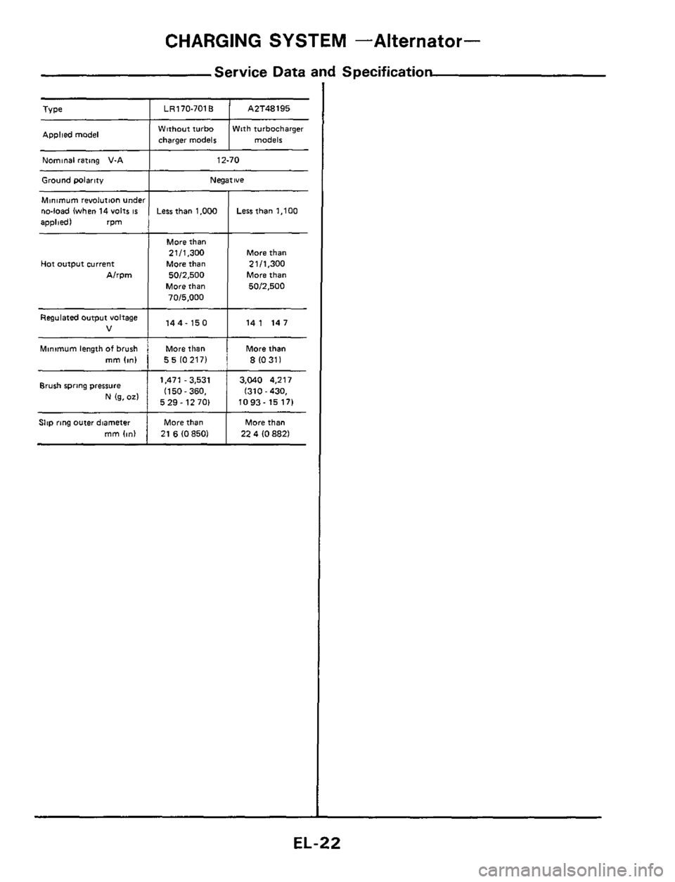
Service Data and Specification
LR170-701B
Applied model
A2T48195
Nominal rating V-A
Ground wlarity
Minimum revolution undt no-load (when 14 volts IS
applied) rpm
Hot output current
Alrpm
Regulated output voltage
V
Minimum length of brush rnm (m)
Brush spring pressure
N 1% 02)
Slip ring outer diameter
mm Ion)
W8thout turbo With turbocharger
charaer models models
12-70
Negative
Less than 1.000
More than
2111,300
More than
5012,500
More than
7015,000
144-150
More than
55102171
1,471 - 3,531
1150-360.
5 29
- 12 701
More than
21
6 IO 850)
Less than 1,100
More than
21 11,300
More than
5012,500
141 147
More than
8 10311
3,040 4,217
I310
- 430,
1093- 15 17)
More than
22 4
10 8821