NISSAN 300ZX 1984 Z31 Electrical System Workshop Manual
300ZX 1984 Z31
NISSAN
NISSAN
https://www.carmanualsonline.info/img/5/567/w960_567-0.png
NISSAN 300ZX 1984 Z31 Electrical System Workshop Manual
Page 1 of 116
ELECTRICAL SYSTEM
I
SECTION EL
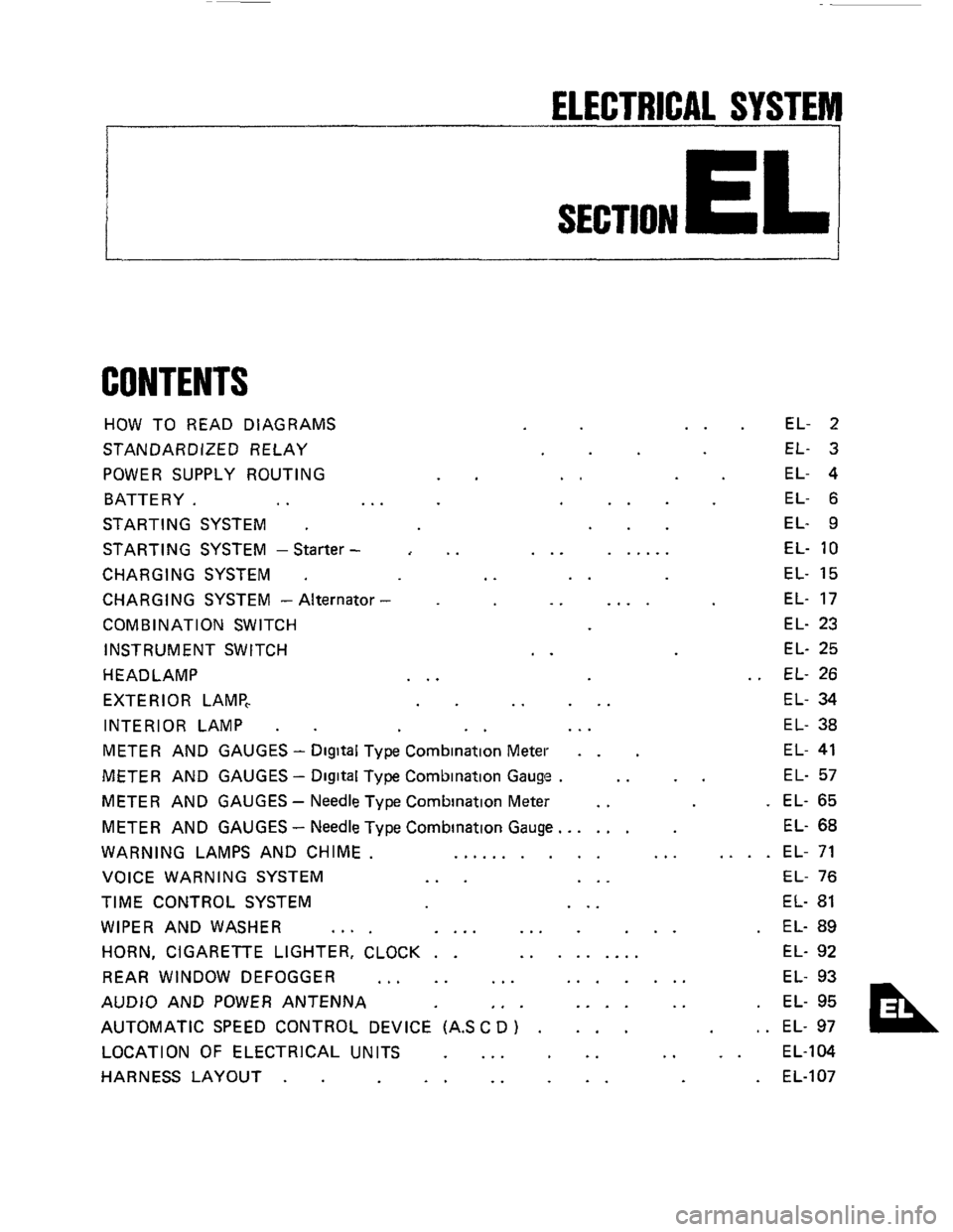
CONTENTS
HOW TO READ DIAGRAMS
STANDARDIZED RELAY
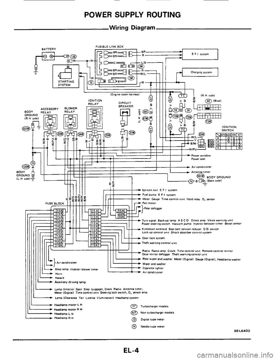
POWER SUPPLY ROUTING
BATTERY.
.. ..
STARTING SYSTEM .
STARTING SYSTEM -Starter -
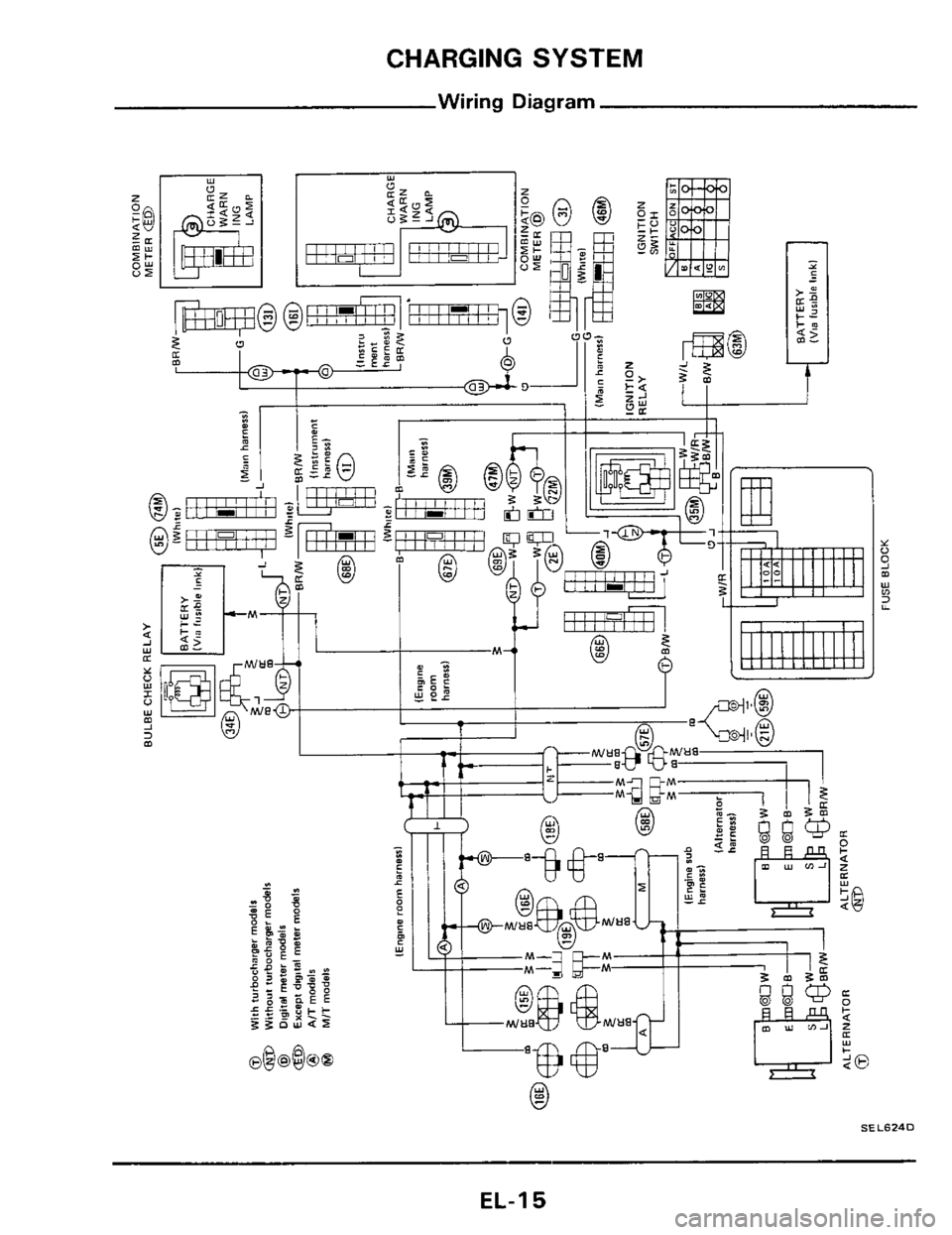
CHARGING SYSTEM .
CHARGING SYSTEM - Alternator
COMB IN AT1 ON SWITCH
INSTRUMENT SWITCH
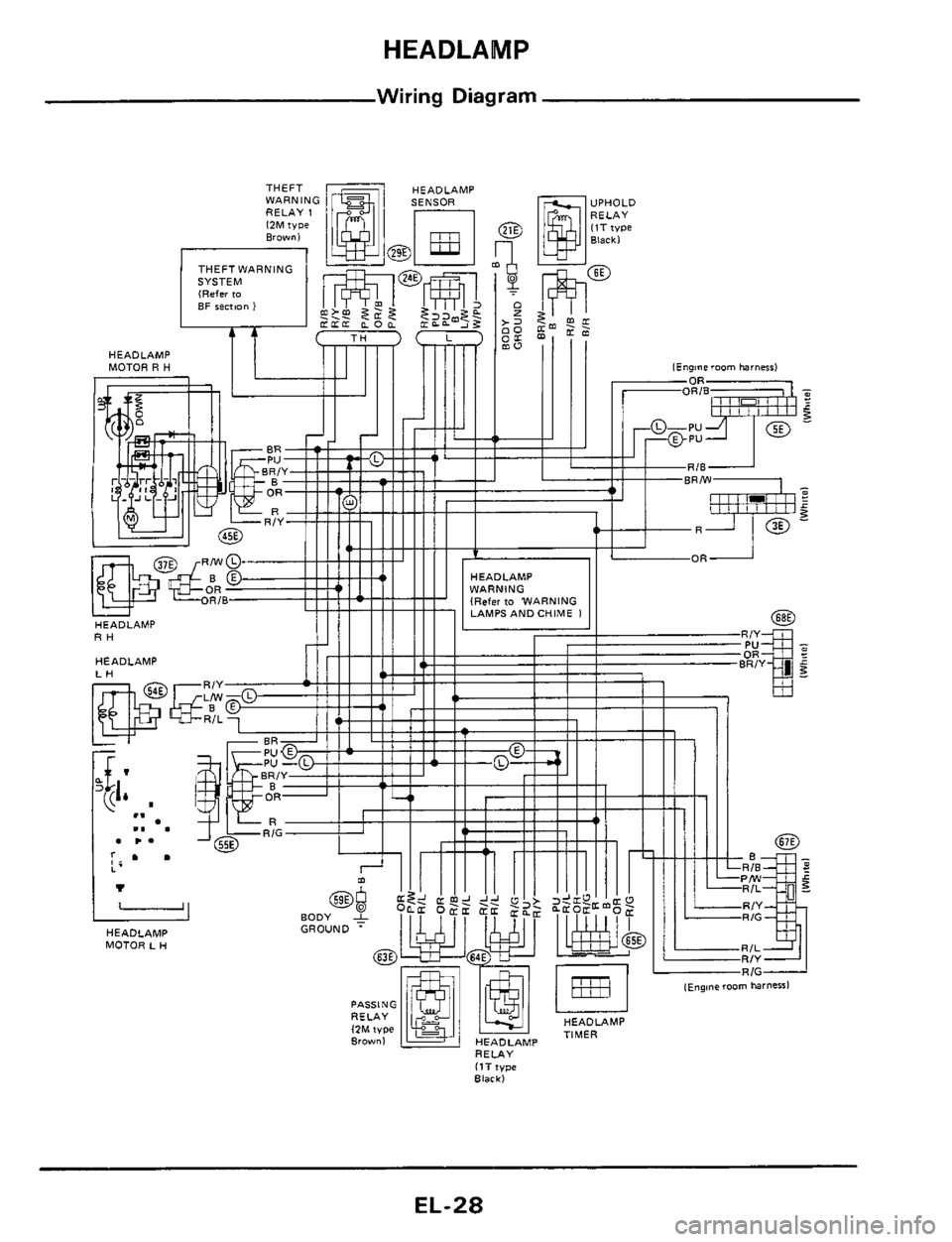
HEADLAMP
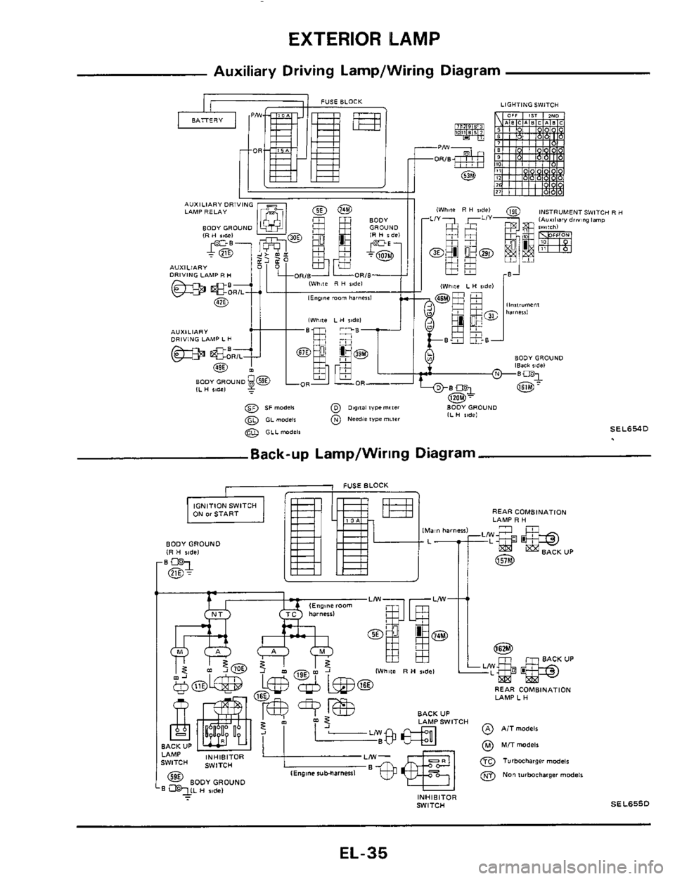
EXTERIOR LAMP,
INTERIOR LAMP
.
..
..
..
..
..
... ......
..
.. ....
..
.. ...
EL- 2
EL- 3
EL- 4
EL- 6
EL- 9
EL-
10
EL- 15
EL- 17
EL- 23
EL- 25
EL- 26
EL- 34
EL- 38
METER AND GAUGES - Digital Type Combination Meter . . EL- 41
METER AND GAUGES - Digital Type Combination Gauge . .. .. EL- 57
METER AND GAUGES - Needle Type Combination Meter .. . EL- 65
METER AND GAUGES
- Needle Type Combination Gauge.. .... EL- 68
WARNING LAMPS AND CHIME. .......... ... .... EL- 71
VOICE WARNING SYSTEM
... ... EL- 76
TIME CONTROL SYSTEM ... EL- 81
WIPER AND WASHER .... .... ... ... . EL- 89
HORN, CIGARETTE LIGHTER, CLOCK . . ......... EL- 92
REAR WINDOW DEFOGGER
... .. ... ....... EL- 93
AUDIO AND POWER ANTENNA
,. . .... .. . EL- 95
AUTOMATIC SPEED CONTROL DEVICE (AS
C D ) . ... , . EL- 97
LOCATION OF ELECTRICAL UNITS
... .. .. .. EL-104
HARNESS LAYOUT
. . .. .. .. . EL-107
Page 2 of 116
HOW TO READ DIAGRAMS
I
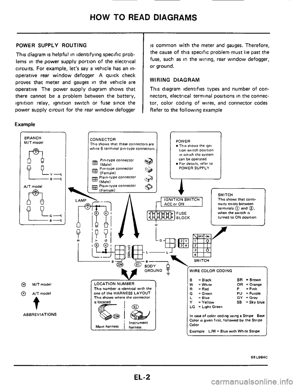
POWER SUPPLY ROUTING
This diagram is helpful in identifying specific prob-
lems
in the power supply portion of the electrical
circuits. For example, let's say
a vehicle has an in-
operative
rear window defogger A quick check
proves that meter and
gauges in the vehicle are
operative The power supply diagram shows that
there cannot be
a problem between the battery,
ignition relay, ignition switch or fuse since the
power supply circuit for the
rear window defogger
Example
BRANCH M/T model
AlT model
n
@ M/Tmodel
@ AITmodel
t
ABBREVIATIONS
is common with the meter and gauges. Therefore,
the cause of this specific problem must
lie past the
fuse, such
as in the wiring, rear window defogger,
or ground.
WIRING DIAGRAM
This diagram identifies types and number of con-
nectors, electrical
terminal positions in the connec-
tor, color coding of wires, and connector codes
Refer to the following example
CONNECTOR This shows that there connectors are white 6 terminal pin-type connectors
Pin-type connector (Male)
(Female)
(Male)
(Female)
833 Piaan-type connector
gg Piatn-type connector
POWER This shows the tgni tion witch ~osition ~n which the system can be operated For deiailr, refer 10 POWER SUPPLY
A r
I
1 v SWITCH ., , ,-,. -..,m I This shows that conti-
u
f
L-
WIRE COLOR CODING
This number IS !dentical with the one of the HARNESS LAYOUT This show where the mnnenor
CarON I nutty exists between termmels @ and 0, when the switch 16 turned 10 ON rmition
B W R
BR =Brown = Black OR =Orange =White =Red P =Pink G =Green PU =Purple L =Blue GY =Gray Y =Yellow SB =Sky blue LG = Laghi Green
In case of color coding using a Stripe Bare Color IS given fmt. followed by the Stripe Color
Example LIW = Blue with White Stripe
EL-2
Page 4 of 116
~ POWER SUPPLY ROUTING
Wiring
Diagram
FUSIBLE LINK BOX 8ATTERY BR
-
STARTING
Charging system
rc- I
-Power wmdow
EL-4
Page 9 of 116
STARTING SYSTEM
Wiring Diagram
MIT MODELS FUSIBLE LINK BOX
THEFT WARNING
RELAY 2
IGNITION
SWITCH
-1
- STARTER MOTOR
AIT MODELS
lNHlBlTOR SWITCH
BATTERY
THEFT
WARNING
RELAY9 INHIBITOR
RELAY .W
FUSIBLE LINK BOX
EL-9
Page 15 of 116
CHARGING SYSTEM
Wiring Diagram
SEL6240
EL-I 5
Page 28 of 116
HEADLAMP
Wiring Diagram
HEADLAMP
MOTOR R H
RH
HEADLAMP
HEADLAMP
MOTOR L H
HEADLAMP
RELAY
ItT type Black)
EL-28
Page 35 of 116
EXTERIOR LAMP
Auxiliary Driving Lamp/Wiring Diagram
Back-up Lamp/Wiring Diagram
BODYGROUND (R H $idel
1 FUSEBLOCK -
REAR COMBINATION
LAMP R H IMsin hsmenl
IWh8te R H ridel
lEng8nc rubharnenl @ Non WrMcharger models @ BODY GROUND qCL H sidel - INHIBITOR WITCH SEL655D
EL-35
Page 44 of 116
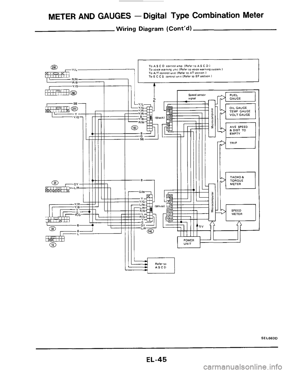
METER AND GAUGES - Digital Type Combination Meter
Wiring Diagram
EL-44
Page 45 of 116
METER AND GAUGES - Digital Type Combination Meter
Wiring Diagram (Cont'd)
GY LIR
tiT POWER
TACH0 & TORDUE METER
SPEED METER
SEL663D
EL-45
Page 58 of 116
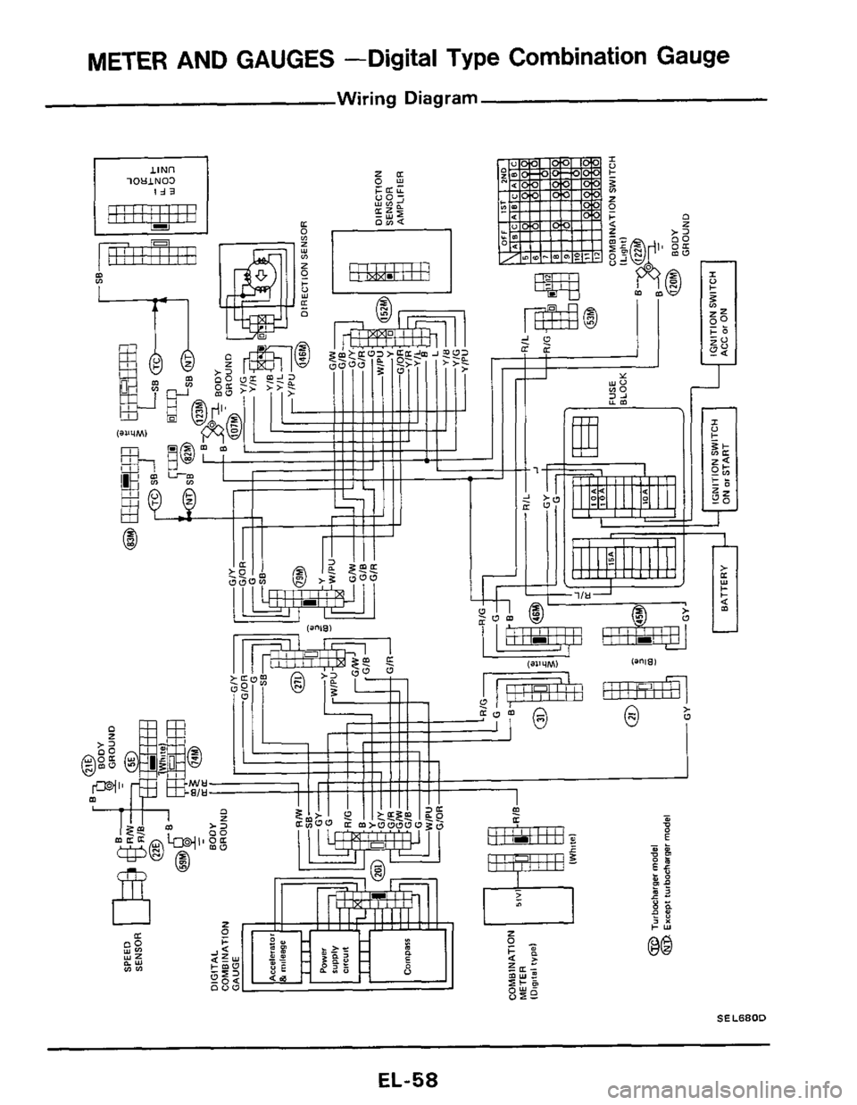
METER AND GAUGES -Digital Type Combination Gauge
Wiring Diagram
lOUlN03
m m
.? I
@q .
w-@ I I
SEL680D
EL-58


