Turbo NISSAN 300ZX 1984 Z31 Engine Fuel And Emission Control System Workshop Manual
[x] Cancel search | Manufacturer: NISSAN, Model Year: 1984, Model line: 300ZX, Model: NISSAN 300ZX 1984 Z31Pages: 79, PDF Size: 2.15 MB
Page 1 of 79

ENGINE FUEL &
- EMISSION - CONTROL SYSTEM
SECTION EFaEC
CONTENTS
PRECAUTIONS ..
COMPONENT PARTS LOCATION
ECCS DIAGRAM
. . .
ECCS CHART ..
ECC.S WIRING DIAGRAM . . ..
FUEL FLOW SYSTEM DESCRIPTION .
AIR FLOW SYSTEM DESCRIPTION ....
E C C S. DESCRIPTION . . . . ...
DIAGNOSTIC PROCEDURE . ..
SE LF-D I AGNOSIS ..
..
.. ..
..
..
..
...
ELECTRONfC CONTROL SYSTEM INSPECTION
MIXTURE RATIO FEEDBACK SYSTEM INSPECTION
. ,
FUEL SYSTEM INSPECTION
TURBOCHARGER
. ... ..
INJECTOR COOLING FAN (VG30ET) .
PRESSURE REGULATOR CONTROL
CRANKCASE EMISSION CONTROL SYSTEM
. . . .
EXHAUST EMISSION CONTROL SYSTEM . . ...
EVAPORATIVE EMISSION CONTROL SYSTEM . . .
SERVICE DATA AND SPECIFICATIONS (S DS). . . . . . .
. . EF&EC- 2
. EF&EC- 3
EF & EC- 4
EF&EC- 6
EF&EC- 8
.. EF & EC-10
EF
& EC-11
, EF&EC-13
EF
& EC-28
EF
& EC-35
EF
& EC43
EF & EC-60
EF
& EC-63
EF
& EC-66
EF
& EC-69
EF
& EC-72
. . EF & EC-74
EF
& EC-75
, EF&EC-76
EF & EC-79
Page 4 of 79

E. C.C. S. DIAGRAM
VG30E Engine (Without turbocharger)
SEF602B
EF & EC-4
Page 5 of 79
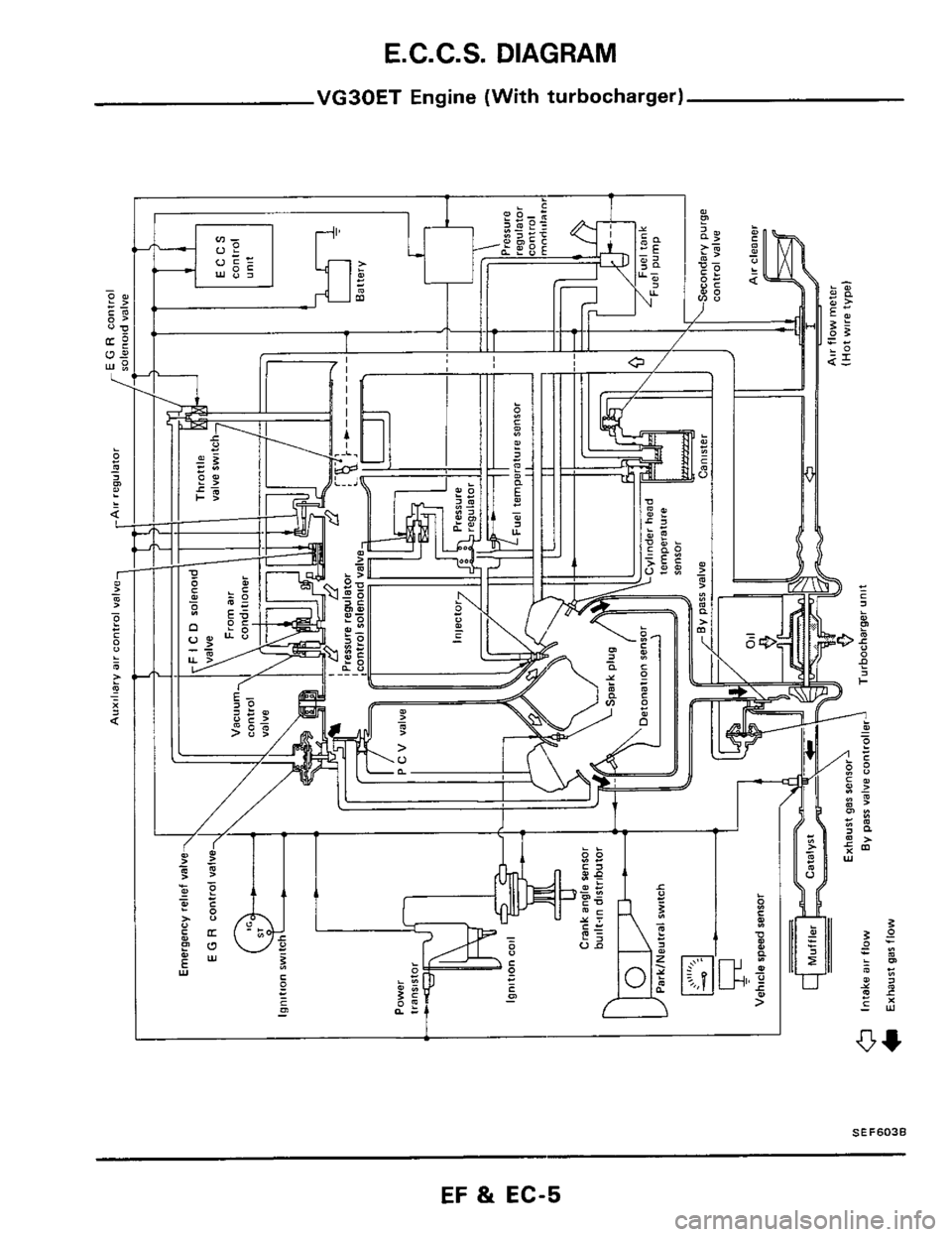
E.C.C.S. DIAGRAM
VG30ET Engine (With turbocharger)
L
SEF603B
EF & EC-5
Page 6 of 79
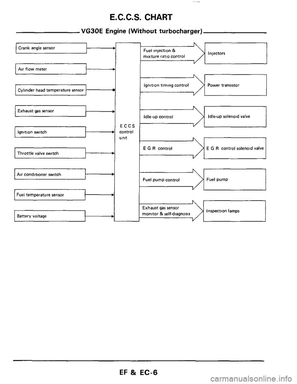
E.C.C.S. CHART
Exhaust gas sensor t
b
Throttle valve switch -b
VG30E Engine (Without turbocharger)
ECCS
control
unit
Crank angle sensor
%el pump control Fuel pump
Air conditioner switch 1 t
Battery voltage
- I
Injectors Fuel injection &
mixture ratio control
VI 1
1
Ignition timing control Power transistor
Idle-up control Idle-up solenoid valve
E G R control E G R control solenoid valve
-1 I
Inspection lamps ixhaust gas sensor
nonitor
& self-diamosis
EF & EC-6
Page 7 of 79
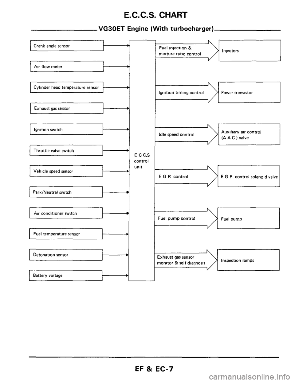
E. C. C.S. CHART
VG30ET Engine (With turbocharger)
Air flow meter c
Cylinder head temperature sensor b
b
Ignition switch b
Throttle valve switch I b
b
Park/Neutral switch
Air conditioner switch I
b
E C C.S
control
unit
b
Injectors Fuel injection &
mixture ratio control
--I
Ignition timing control Power transistor
-dI Auxiliary air control
(A A
C ) valve Idle speed control
I YL
E G R control E G R control solenoid valve
Fuel pump control Fuel pump
Inspection lamps ixhaust gas sensor
nonitor
& self diagnosis I
EF & EC-7
Page 11 of 79
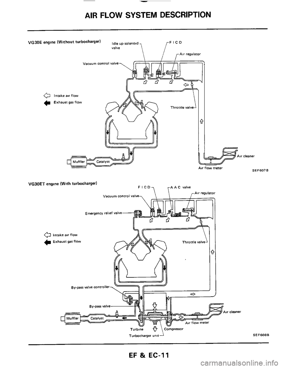
AIR FLOW SYSTEM DESCRIPTION
Air cleaner
VG30E engine (Without turbocharger) up roleno,,, FlCD
r
Valve
0 Intake air flow
C Exhaust gar flow
VGJOET engine (With turbocharger)
Vacuum control valve
Emergency relief valve
0 Intake air flow
Exhaust gar flow
cleaner
Turbbne
Turbocharger - unit- \Compresor SE F 608 B
EF & EC-11
Page 12 of 79
AIR FLOW SYSTEM DESCRIPTION
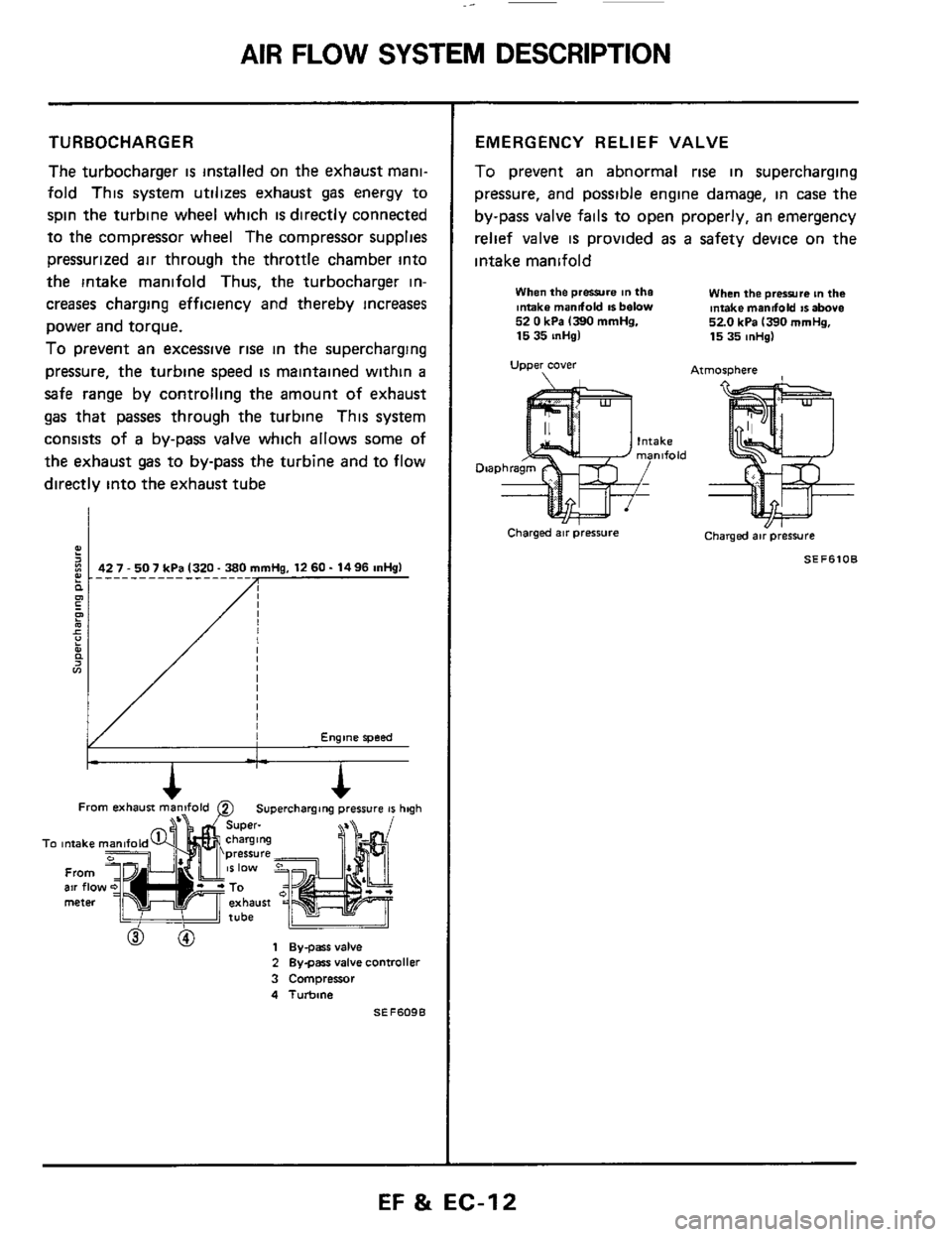
TURBOCHARGER
The turbocharger is installed on the exhaust mani-
fold This system utilizes exhaust gas energy to
spin the turbine wheel which
is directly connected
to the compressor wheel The compressor supplies
pressurized air through the throttle chamber into
the intake manifold Thus, the turbocharger in-
creases charging efficiency and thereby increases
power and torque.
To prevent an excessive rise in the supercharging
pressure, the turbine speed
is maintained within a
safe range by controlling the amount of exhaust
gas that passes through the turbine This system
consists of
a by-pass valve which allows some of
the exhaust gas to by-pass the turbine and to flow
directly into the exhaust tube
Engine speed
From b==iF exhausi man2fold 0 Superchargang pressure 41 hqh
To intake
From air flo meter
h
To intake
From air flo meter
2 Bygars valve controller
3 Compressor
4 Turbine
SEF609B
EMERGENCY RELIEF VALVE
To prevent an abnormal rise in supercharging
pressure, and possible engine damage, in case
the
by-pass valve fails to open properly, an emergency
relief valve
is provided as a safety device on the
intake manifold
When the prwre in the Intake mandold IS below 52 0 kPa 1390 mmHg. 15 35 inHgl
Upper cover
When the prerrura tn the intake mandold IS above 520 kPa 1390 mrnHg, 15 35 mHg)
Atmosphere
Charged air pressure Charged air pressure
SEF6lOB
EF & EC-12
Page 30 of 79

DIAGNOSTIC PROCEDURE
Driveabil
1. Inspect engine and E C C.S. for air leaks,
proper electrical connections, etc
1) Check all hoses and ducts for air leaks
2) Check air cleaner for clogging
3) Check harness connectors for proper connec-
tions
4) Check ignition wiring
5) Check gaskets for leaks at all air intake com-
ponents
6) Check E G.R valve operation
7) Check air regulator operation
2 Perform E C C S self-diagnosis
Follow the procedure in E CCS SELF-
DIAGNOSIS (Page EF & EC-35)
3 Check idle speed and ignition timing
a. Prepare the following conditions:
Headlampswitch' OFF
Heater blower: OFF
Air conditioner switch: OFF
Front wheel (Power steering model):
KEEP STRAIGHT AHEAD
b. Warm engine to operating temperature.
Check
and adjust as follows
[VG30E engine (Without turbocharger)]
1) Stop engine and disconnect idle-up solenoid
valve harness connector
Idle-up solenoid
2) Start engine and race engine two or three times
under no-load, then run engine
at idle speed
(Cont'd)
3) Check idle speed
M/T & A/T (in "D" position)
700250 rpm at sea level
650250 rpm at high altitude condition
If necessary, adjust to the specified
speed by
turning idle speed adjusting screw
I, SEF6456
4) Stop engine and connect idle-up solenoid valve
harness connector
5) Start engine and check ignition timing with
a
timing light
20ai2" B.T.D.C.
If necessary, adjust ignition
timing by turning
distributor
[VG30ET engine (With turbocharger)]
1) Race engine two or three times under no-load,
then run engine at idle speed
2) Check idle speed.
M/T: 70W50rpm
A/T: 650k50 rpm (in "D" position)
EF & EC-30
Page 33 of 79
DIAGNOSTIC PROCEDURE
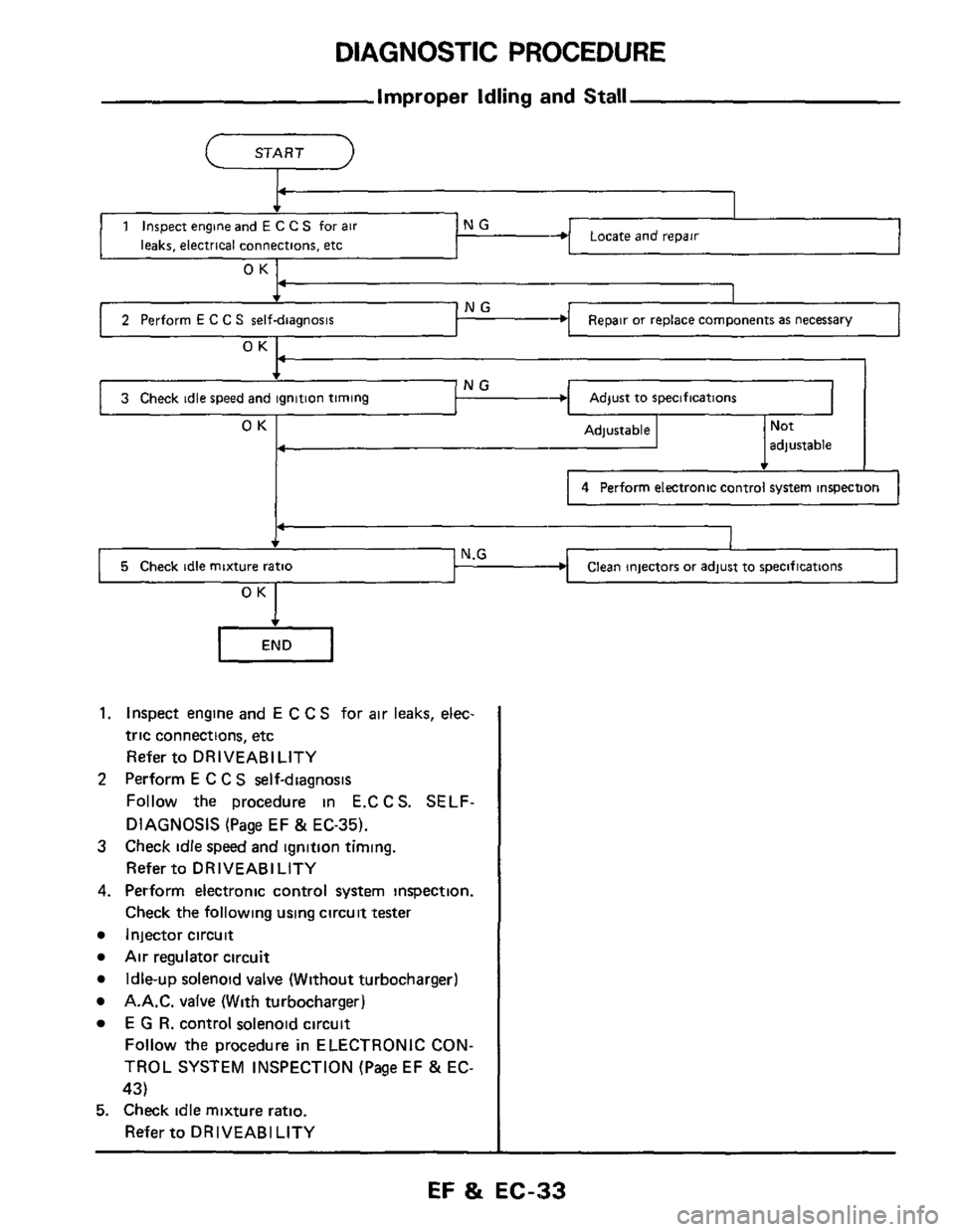
5 Check idle mixture ratio
Improper Idling and Stall
START 2
N.G Clean injectors or adjust to specifications
Locare ano repair
1
NG 4 I
2 Perform E C C S self-diagnosis Repair or replace components as necessary J OK
Adjust to specifications NG 3 Check idle speed and ignition timing
OK Adjustable adjustable
4 Perform electronic control system inspection
OK I
1. Inspect engine and E C C S for air leaks, elec-
tric connections, etc
Refer to DRIVEABILITY
Perform
E C C S self-diagnosis
Follow the procedure in E.CCS. SELF-
DIAGNOSIS
(Page EF & EC-35).
3 Check idle speed and ignition timing.
Refer to DRIVEABILITY
4. Perform electronic control system inspection.
Check the following using circuit tester
Injector circuit
Air regulator circuit
A.A.C. valve (With turbocharger)
2
Idle-up solenoid valve (Without turbocharger)
E G R. control solenoid circuit
Follow the procedure in ELECTRONIC CON-
TROL SYSTEM INSPECTION (Page EF
& EC-
43)
Refer to DRIVEABILITY
5. Check idle mixture ratio.
EF & EC-33
Page 50 of 79
ELECTRONIC CONTROL SYSTEM INSPECTION
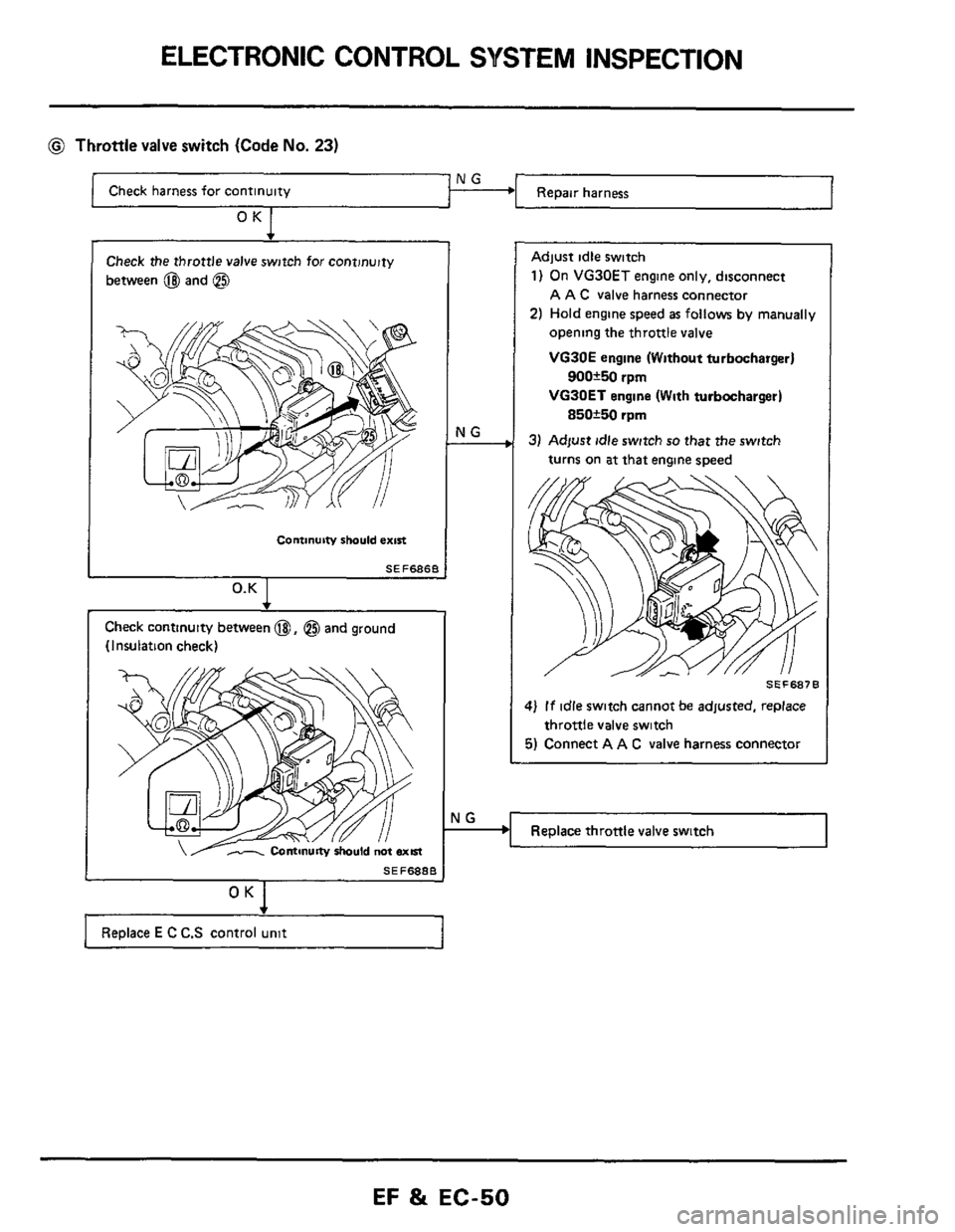
@ Throttle valve switch (Code No. 23)
Check harness for continuity
OK 1
Check the throttle valve switch for continuity
between
@ and @
Continuitv should exin
SEF686B
0.K I
Check continuity between @, @$ and ground
(Insulation check)
SEF6888
+
Replace E C C.S control unit
rlG
Adjust idle switch
1) On VG30ET engine only, disconnect
A A C
valve harness connector
2) Hold engine speed as follows by manually
opening the throttle
valve
VG30E engine (Without turbocharger)
VG30ET engine (With turbocharger)
3) Adfust idle switch so that the switch
900+50 rpm
850*50 rpm
turns on at that engine speed
SEF687B
1) If idle switch cannot be adjusted, replace
5) Connect A A C valve harness connector
throttle valve switch
Replace throttle valve switch
EF 81 EC-50