cylinder head NISSAN 300ZX 1984 Z31 Engine Fuel And Emission Control System Workshop Manual
[x] Cancel search | Manufacturer: NISSAN, Model Year: 1984, Model line: 300ZX, Model: NISSAN 300ZX 1984 Z31Pages: 79, PDF Size: 2.15 MB
Page 7 of 79
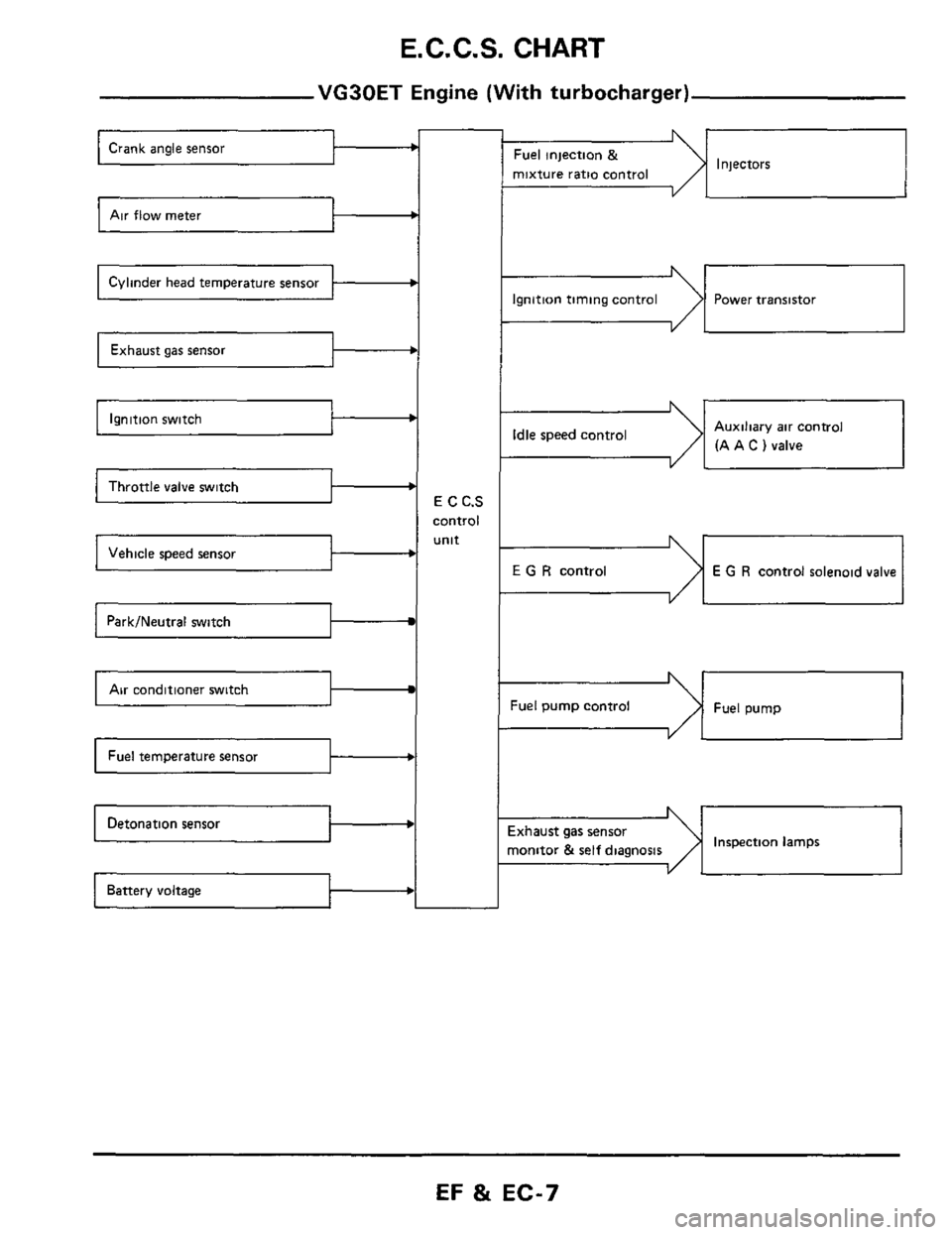
E. C. C.S. CHART
VG30ET Engine (With turbocharger)
Air flow meter c
Cylinder head temperature sensor b
b
Ignition switch b
Throttle valve switch I b
b
Park/Neutral switch
Air conditioner switch I
b
E C C.S
control
unit
b
Injectors Fuel injection &
mixture ratio control
--I
Ignition timing control Power transistor
-dI Auxiliary air control
(A A
C ) valve Idle speed control
I YL
E G R control E G R control solenoid valve
Fuel pump control Fuel pump
Inspection lamps ixhaust gas sensor
nonitor
& self diagnosis I
EF & EC-7
Page 15 of 79
E. C. C. S. DESCRIPTION
E.C.C.S. Corn1
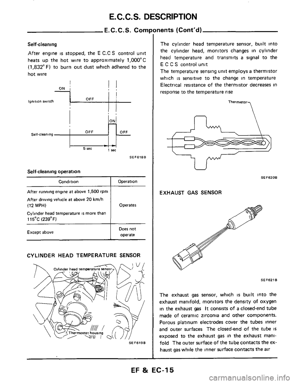
Self-cleaning
After engine is stopped, the E C.C S control unit
heats up the hot wire to approximately
1,OOO"C
(1,832"F) to burn out dust which adhered to the
hot wire
- - 1 rec 5 rec
SEF618B
Self-cleaning operation
Condition _____~ ~
After running engine at above 1,500 rpm
After driving vehicle at above
20 kmlh
(12 MPH)
Cylinder head temperature is more than
115OC
(239°F)
Except above
Operation
Operates
Does not
operate
CYLINDER HEAD TEMPERATURE SENSOR
SEF6198
nents (Cont'd)
The cylinder head temperature sensor, built into
the cylinder head, monitors changes in cylinder
head temperature and transmits
a signal to the
E C C S control unit
The temperature sensing unit employs
a thermistor
which
is sensitive to the change in temperature
Electrical resistance
of the thermistor decreases in
response to the temperature
rise
Thermmor
U
SEF6208
EXHAUST GAS SENSOR
SEF621
The exhaust gas sensor, which is built into the
exhaust manifold, monitors the density
of oxygen
in the exhaust gas It consists of a closed-end tube
made
of ceramic zirconia and other components.
Porous platinum electrodes cover the tubes inner
and outer surfaces The closed-end
of the tube IS
exposed to the exhaust gas in the exhaust mani-
fold The outer surface
of the tube contacts the ex-
haust
gas while the inner surface contacts the air
EF & EC-15
Page 20 of 79
E.C.C.S. DESCRIPTION
Fuel Injection Control
Temperature of engine Cylinder head temperature sensor
Density of oxygen in exhaust gas Exhaust gas sensor
Throttle valve idle position ' Throttle valve switch
Engine speed and piston position
Amount of intake air Air flow meter
ECCS
I I
I
control
Gear position unit NeutraVPark switch (VG30ET) I I
Vehicle speed
Start signal
Temperature of fuel
Battery voltage Battery
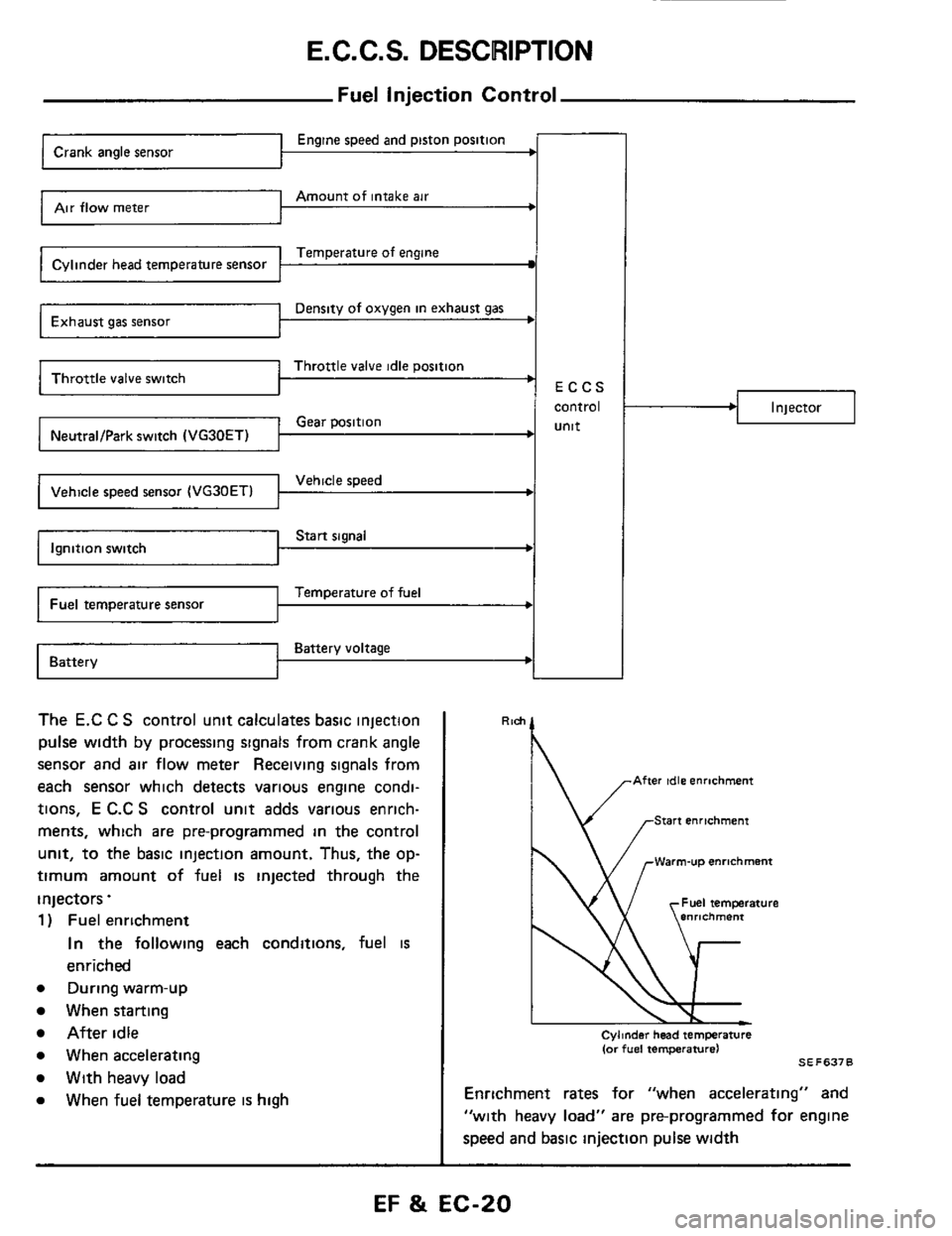
The E.C C S control unit calculates basic injection
pulse
width by processing signals from crank angle
sensor and air flow meter Receiving signals from
each sensor which detects various engine condi-
tions,
E C.C S control unit adds various enrich-
ments, which are pre-programmed
in the control
unit, to the basic injection amount. Thus, the op-
timum amount of fuel is injected through the
injectors.
1 ) Fuel enrichment
In the following each conditions, fuel is
enriched
e During warm-up
When starting
After idle
e When accelerating
e With heavy load
e When fuel temperature is high
.I Injector
Rlch
' \/ .-Warm-u~ enrichment
Cylmder head temperature (or fuel temperature1 SE F637 0
Enrichment rates for "when accelerating" and
"with heavy load" are pre-programmed for engine
speed and basic injection pulse
width
EF & EC-20
Page 22 of 79
E.C.C.S. DESCRIPTION
-Fuel injection Control (Cont'd)-
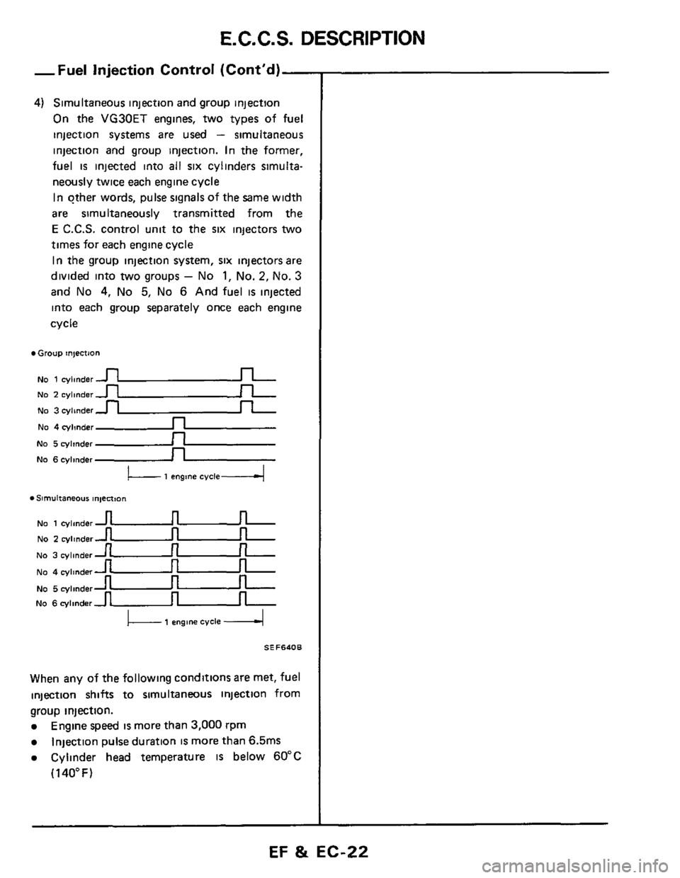
4) Simultaneous injection and group injection
On the VG30ET engines, two types of fuel
injection systems
are used - simultaneous
injection and group injection. In the former,
fuel is injected into all six cylinders simulta-
neously twice each engine cycle
In other words, pulse signals
of the same width
are simultaneously transmitted from the
E C.C.S. control unit to the six injectors two
times for each engine cycle
In the group injection system, six injectors are
divided into
two groups - No 1, No. 2, No. 3
and No 4, No 5, No 6 And fuel is injected
into each group separately once each engine
cycle
Group injection
NO 1 cylmder u
No 5 cylinder n
No 6cylinder _n
No 1 cylinder u
NO 2 cylinder -
u
u
u
u
NO 2 cylinder-
No 3 cylinder -
No 4 cylmdern
L- 1 engine cvcle4
. Slrnultaneous ln,ect,On
No 3 cylinder
No 4 cylinder
No 5 cylinder
No 6 cylinder
I 1 engm cycle I
SEF640B
When any of the following conditions are met, fuel
injection shifts to simultaneous injection from
group injection.
Engine speed is more than 3,000 rpm
Injection pulse duration is more than 6.5ms
Cylinder head temperature IS below 60°C
(1 40" F)
EF & EC-22
Page 23 of 79
E. C. C. S. DESCRIPTION
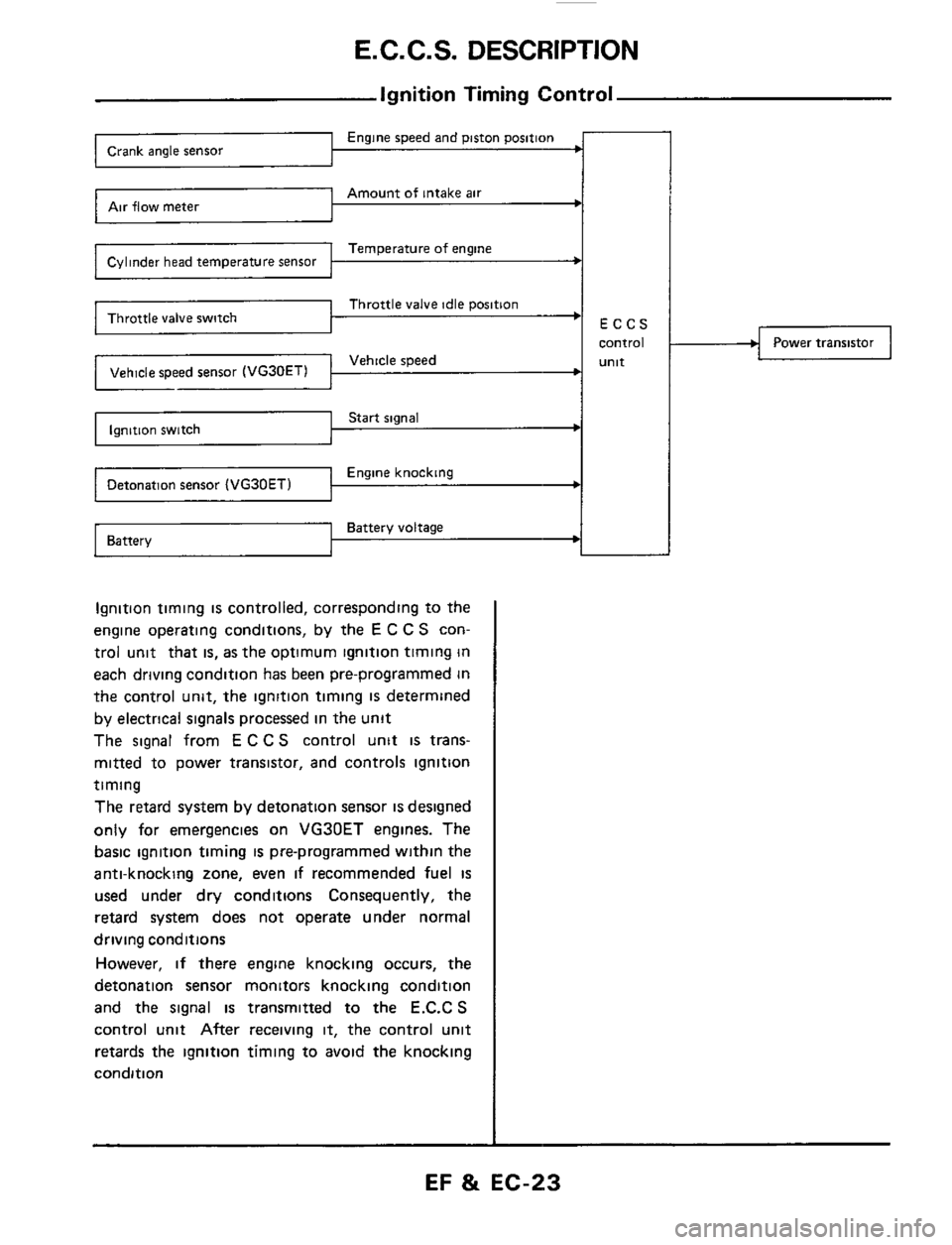
Ignition Timing Control
Engine speed and piston position Crank angle sensor
Amount of intake air Air flow meter
Temperature of engine Cylinder head temperature sensor
Throttle valve idle position
Vehicle speed Vehicle speed sensor (VG30ETl 1 I I
Start signal Ignition switch
Engine knocking Detonation sensor
Battery voltage Battery ~
Ignition
timing is controlled, corresponding to the
engine operating conditions, by the
E C C S con-
trol unit that
is, as the optimum ignition timing in
each driving condition has been pre-programmed in
the control unit, the ignition timing
IS determined
by electrical signals processed in the unit
The signal from
E C C S control unit is trans-
mitted to power transistor, and controls ignition
timing
The retard system by detonation sensor
is designed
only for emergencies on VG30ET engines. The
basic ignition timing
is pre-programmed within the
anti-knocking zone, even
if recommended fuel is
used under dry conditions Consequently, the
retard system does not operate under normal
driving conditions
However,
if there engine knocking occurs, the
detonation sensor monitors knocking condition
and the signal is transmitted to the E.C.C S
control unit After receiving it, the control unit
retards the ignition timing to avoid the knocking
condition
Power transistor
EF & EC-23
Page 25 of 79
E. C. C. S. DESCRIPTION
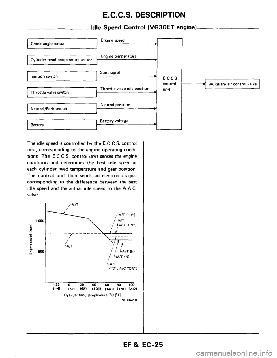
Start signal ’ Ignition switch
Throttle valve idle position
Neutral position t
Battery voltage Battery
Idle Speed Control (VG30ET engine)
Engine speed
Engine temperature
ECCS
control
Unlt
-
The idle speed is controlled by the E.C C S. control
unit, corresponding to the engine operating condi-
tions
The E C C S control unit senses the engine
condition and determines the best idle speed
at
each cylinder head temperature and gear position
The control unit then sends an electronic signal
corresponding
to the difference between the best
idle speed and the actual idle speed to the A A C.
valve.
I
,/ lAiC”ON”1 -‘I E .. -
P - 0 E 4 1 - - - -L- - - - - - lZN)
500 w
LAiT (”0”. A/C ”ON1
I -20 0 20 40 60 80 1M) 14) I321 168) 11041 1140) 1176) (212)
Cylinder head ternprature “C (OF1
SEF641B
Auxiliary air control valve
EF & EC-25
Page 35 of 79
SELF-DIAGNOSIS
Self-diagni
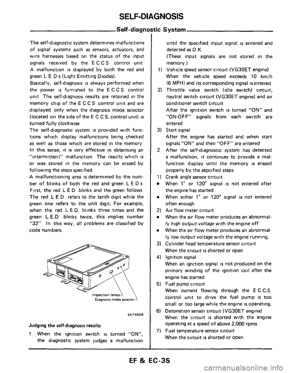
The self-diagnostic system determines malfunctions
of signal systems such as sensors, actuators, and
wire harnesses based on the status of the input
signals received by the
E C C S control unit
A malfunction is displayed by both the red and
green
L E D s (Light Emitting Diodes).
Basically, self-diagnosis
is always performed when
the power
is furnished to the E C C S control
unit The self-diagnosis results
are retained in the
memory chip of the
E C C S control unit and are
displayed only when the diagnosis mode selector
(located on
the side of the E C C S. control unit) is
turned fully clockwise
The self-diagnostic system
is provided with func-
tions which display malfunctions being checked
as well as those which are stored in the memory
In
this sense, it is very effective in determing an
"intermittent" malfunction The results which
is
or was stored in the memory can be erased by
following the steps specified
A malfunctioning area is determined by the num-
ber of blinks of both the
red and green L E D s
First, the red L E D blinks and the green follows
The red L E D refers to the tenth digit while the
green
one refers to the unit digit. For example,
when the red L
E D. blinks three times and the
green
L E.D blinks twice, this implies number
"32" In this way, all problems are classified by
code numbers.
inspection lamps1 Diagnosis mode
SEF6508
Judging the selfdiagnosis results
1 When the ignition switch is turned "ON",
the diagnostic system judges
a malfunction
tic System
until the specified input signal is entered and
detected
as 0 K
(These input signals are not stored in the
memory
)
1) Vehicle speed sensor circuit (VG30ET engine)
When the vehicle speed exceeds
10 km/h
(6 MPH) and its corresponding signal is entered
2) Throttle valve switch (idle switch) circuit,
neutral switch circuit (VG30ET engine) and
air
conditioner switch circuit
After the ignition switch
is turned "ON" and
"ON-OFF"
signals from each switch are
entered
3) Start signal
After the engine has started and when start
signals "ON" and then "OFF" are entered
2 After the self-diagnostic system has detected
a malfunction, it continues to provide a mal-
function display until the memory
is erased
properly by the sepcified steps
1) Crank angle sensor circuit
When 1" or 120" signal is not entered after
the engine has started
When either 1" or 120" signal is not entered
often enough
2) Air flow meter circuit
When the air flow meter produces an abnormal-
ly high output voltage with the engine off
When the air flow meter produces an abnormal-
ly low output voltage with the engine running.
3) Cylinder head temperature sensor circuit
When the cricuit
is shorted or open
4) Ignition signal
When an ignition signal
is not produced on the
primary winding of the ignition coil after
the
engine has started
5) Fuel pump circuit
When current flowing through the E
C C.S
control
unit to drive the fuel pump IS too
small or too large while the engine
is operating.
6) Detonation sensor circuit (VG30ET engine)
When the circuit
is shorted with the engine
operating
at a speed of above 2,000 rpms
When the circuit is shorted or open
7) Fuel temperature sensor circuit
EF & EC-35
Page 39 of 79
SELF-DIAGNOSIS
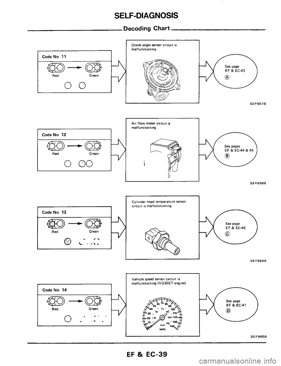
Decoding Chart
I Code No 11
I ked Green
00
1 CodeNo 12
I 'Red Green
0 00
Crank angle sensor circuit IS malfunctioning
Air flow meter circuit IS
malfunctioning 1
See page
EF & EC43
SEF6578
EF & EC44 & 45
1
SEF658B II
I CodeNo 13 I
Cylinder head temperature sensor clrcuit IS malfunctioning
See page EF & EC-46
SEF659B II
Vehtcle speed sensor circuit IS malfunctioning (VG30ET engine)
See page
EF & EC47
Id SEF660B
EF & EC-39
Page 46 of 79
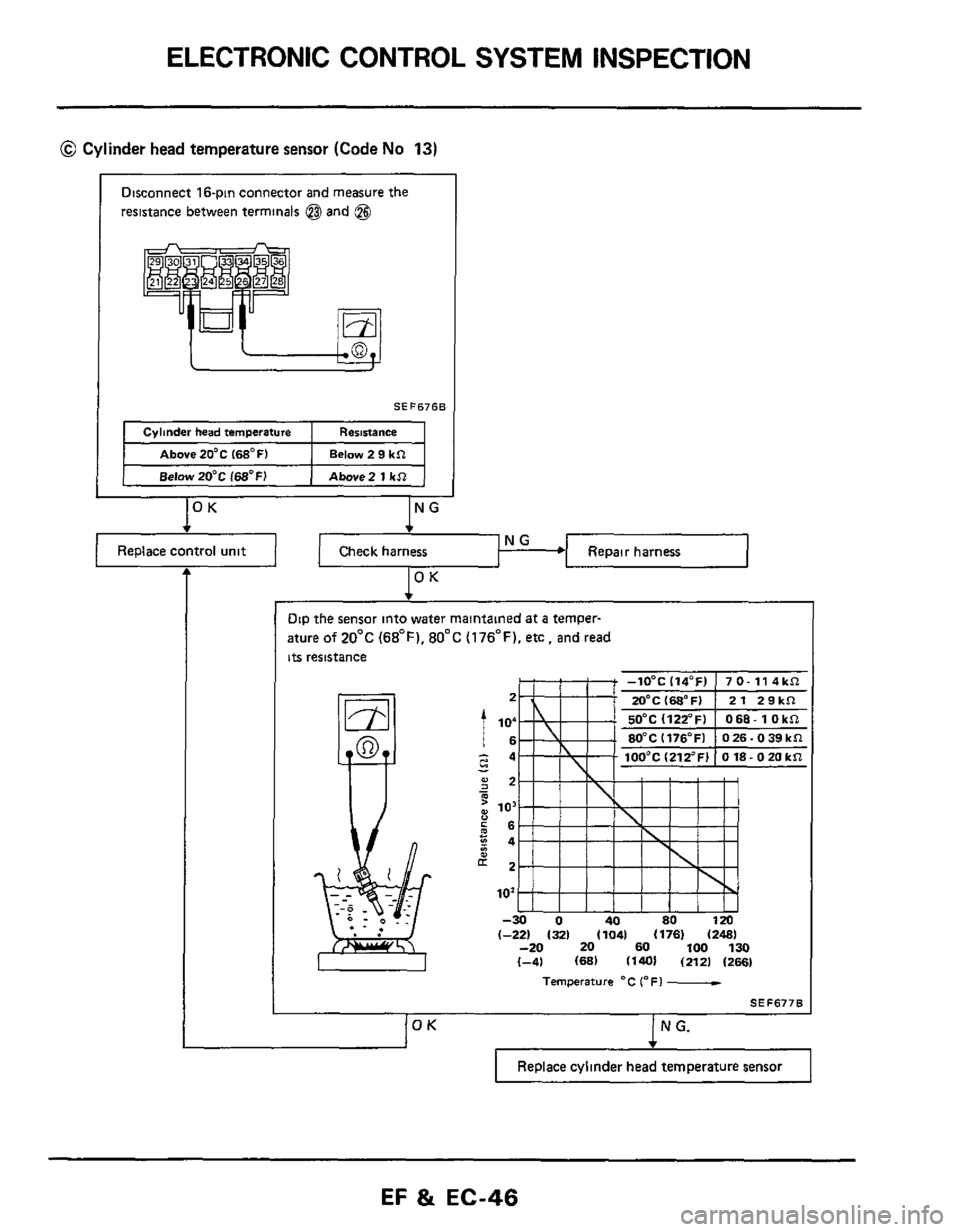
ELECTRONIC CONTROL SYSTEM INSPECTION
@ Cylinder head temperature sensor (Code No 13)
Disconnect 16-pin connector and measure the
resistance between terminals @and
@$
Dip the sensor into water maintained at a temper-
ature
of 20°C (68°F). 80°C (176°F). etc, and read
its resistance
2
I lo; - - c4
- ;2
c 66
g2
m : io3 u
z4 *
102
-30 0 40 80 120 (-221 I321 (1041 11781 (2481 -20 20 60 100 130 (-41 (681 (1401 (2121 (2661
Temperature "C (OF) -
SEF677B
(OK I N G.
Replace cylinder head temperature sensor
EF & EC-46
Page 61 of 79
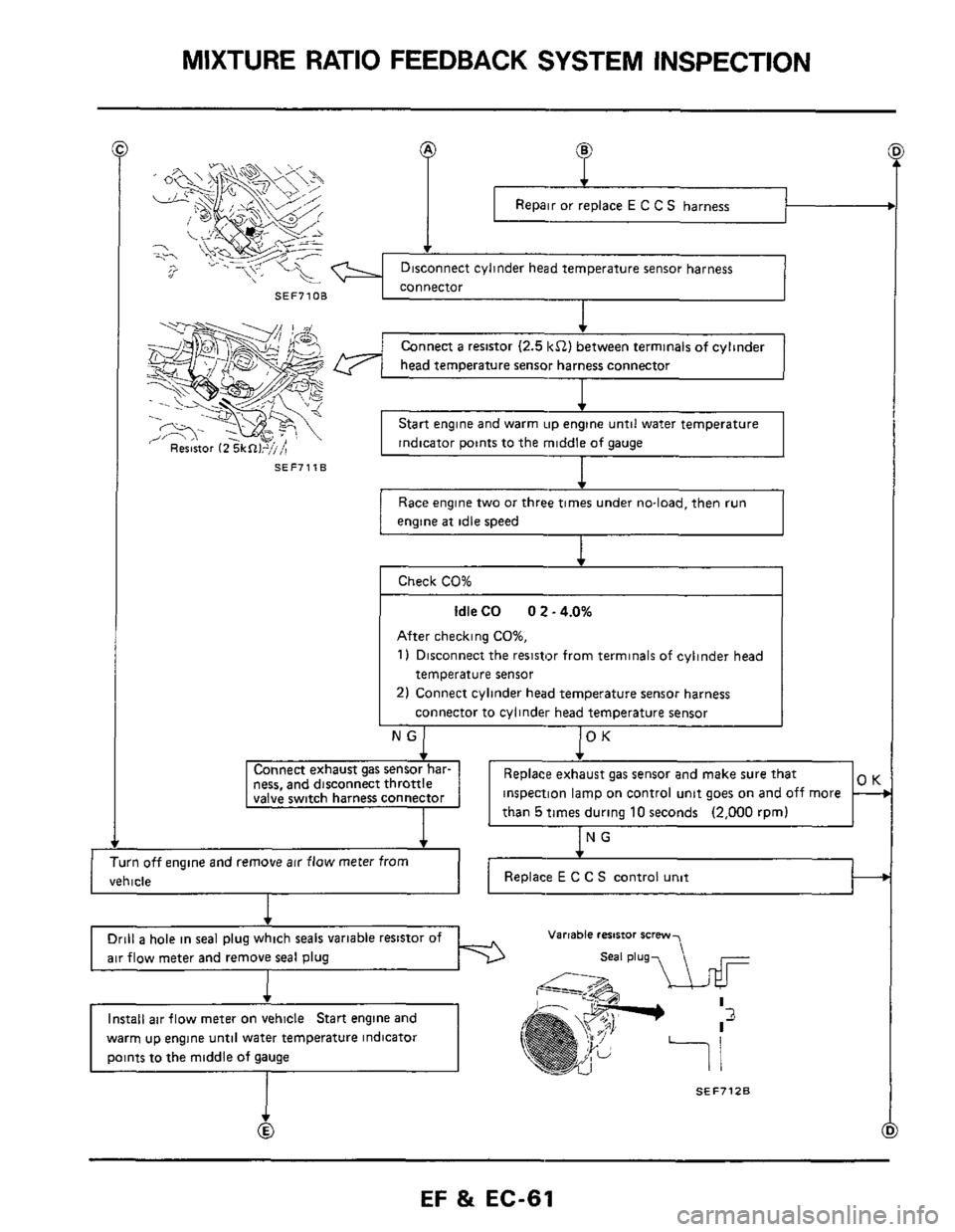
MIXTURE RATIO FEEDBACK SYSTEM INSPECTION
Repair or replace E C C S harness
SEF71OB
SEF7118
f
Connect a resistor (2.5 kS2) between terminals of cylinder
head temperature sensor harness connector
I
Start engine and warm up engine until water temperature
indicator points to the middle
of gauge
Race engine two or three times under no-load. then run
engine
at idle speed
After checking CO%,
1) Disconnect the resistor from terminals of cylinder head
temperature sensor
2) Connect cylinder head temperature sensor harness
connector to cylinder head temperature sensor
ness, and disconnect throttle inspection lamp on control unit goes on and off more
I
Turn off engine and remove air flow meter from
vehicle ~~
Drill a hole
in seal plug which seals variable resistor of
air flow meter and remove seal plug
warm up engine until water temperature indicator
Varrable resistor scmw
SEF7128