heater NISSAN 300ZX 1984 Z31 Engine Fuel And Emission Control System Workshop Manual
[x] Cancel search | Manufacturer: NISSAN, Model Year: 1984, Model line: 300ZX, Model: NISSAN 300ZX 1984 Z31Pages: 79, PDF Size: 2.15 MB
Page 16 of 79

E.C.C.S. DESCRIPTION
E. C. C. S. Corn1
In order to ensure the stable performance of the
exhaust
gas sensor, a ceramic heater is employed
inside the zirconia tube
,-Ceramic zirmnia tube
.- . .. . ... .. . . . . . .. .. --_
SEF622B
THROTTLE VALVE SWlTCl
The throttle valve switch is attached to the throttle
chamber and actuates in response
to accelerator
pedal movement
This switch has idle contact and full throttle con-
tact The idle contact closes when the throttle
valve
is positioned at idle and opens when it is at
any other position.
The full throttle contact
is used only for the
electronic controlled automatic transmission
SEF623B
Full throttle contact p0,nt
nents (Cont'd)
VEHICLE SPEED SENSOR
(VG30ET
engine only)
The vehicle speed sensor provides a vehicle speed
signal
to the E C.C S. control unit
Needle type speedometer models
The speed sensor consists of
a reed switch, which IS
installed in the speed meter unit and transforms
vehicle
speed into a pulse signal.
Magnetic line
\# Reed \I
i : !' sw17CI i N S"
Field 0 plate Field plate
SEF624B
Digital type speedometer models
The speed sensor consists of
an L E D , photo
diode, shutter and wave forming circuit.
Its princi-
ple
is the same as that of the crank angle sensor
011 seal
0 To speedometer cable
SEFS80B
EF & EC-16
Page 19 of 79

E. C. C. S. DESCRIPTION
E.C.C.S. Components (Cont’d)
E.G.R. CONTROL SOLENOID VALVE
E G R control solenoid valve cuts intake manifold
vacuum signal for
E G.R control The solenoid
valve actuates in response to the ON/OFF signal
from
the E C.C S control unit. When the solenoid
is off, vacuum signal from intake manifold is fed
into the
E G R control valve As the control
unit outputs an ON signal, the coil pulls the
plunger downward, and cuts the vacuum signal
9 Atmosphere
ToEGR control valve
From intake
SEF6336 0 manifold
FUEL PUMP
The fuel pump, which is located in the fuel tank, IS
a wet type pump where the vane rollers are directly
coupled to
a motor which is filled with fuel
1 Outlet A
AIR REGULATOR
Air regulator gives an air by-pass when the engine is
cold for the purpose of a fast idle during warm-up
SE F635 B
A bimetal, heater and rotary shutter are built into
the air regulator When the bimetal temperature
IS
low,
the air by-pass port is open As the engine
starts and electric current flows through a heater,
the bimetal begins to rotate the shutter
to close off
the by-pass port The air passage remalns closed
until the engine
is stopped and the bimetal tem-
perature drops
SEF636B
EF & EC-19
Page 30 of 79

DIAGNOSTIC PROCEDURE
Driveabil
1. Inspect engine and E C C.S. for air leaks,
proper electrical connections, etc
1) Check all hoses and ducts for air leaks
2) Check air cleaner for clogging
3) Check harness connectors for proper connec-
tions
4) Check ignition wiring
5) Check gaskets for leaks at all air intake com-
ponents
6) Check E G.R valve operation
7) Check air regulator operation
2 Perform E C C S self-diagnosis
Follow the procedure in E CCS SELF-
DIAGNOSIS (Page EF & EC-35)
3 Check idle speed and ignition timing
a. Prepare the following conditions:
Headlampswitch' OFF
Heater blower: OFF
Air conditioner switch: OFF
Front wheel (Power steering model):
KEEP STRAIGHT AHEAD
b. Warm engine to operating temperature.
Check
and adjust as follows
[VG30E engine (Without turbocharger)]
1) Stop engine and disconnect idle-up solenoid
valve harness connector
Idle-up solenoid
2) Start engine and race engine two or three times
under no-load, then run engine
at idle speed
(Cont'd)
3) Check idle speed
M/T & A/T (in "D" position)
700250 rpm at sea level
650250 rpm at high altitude condition
If necessary, adjust to the specified
speed by
turning idle speed adjusting screw
I, SEF6456
4) Stop engine and connect idle-up solenoid valve
harness connector
5) Start engine and check ignition timing with
a
timing light
20ai2" B.T.D.C.
If necessary, adjust ignition
timing by turning
distributor
[VG30ET engine (With turbocharger)]
1) Race engine two or three times under no-load,
then run engine at idle speed
2) Check idle speed.
M/T: 70W50rpm
A/T: 650k50 rpm (in "D" position)
EF & EC-30
Page 31 of 79

DIAGNOSTIC PROCEDURE
Driveabili
If out of specification, adjust as follows
ness connector
a Stop engine and disconnect A A C valve har-
SEF646B
b Start engine and adjust engine speed by turning
idle speed adjusting screw
M/T: 650 rpm
A/T. 600 rpm (in "D" position)
c. Stop engine and connect A.A.C. valve har-
ness connector Then
start engine
d Make sure that idle speed
is in the specified
range.
3) Check ignition timing with a timing light
ZO"r2" B.T.D.C.
If necessary, adjust ignition timing by turning
distributor
Perform mixture ratio feedback
system inspec-
tion Follow the procedure
in MIXTURE RATIO
4
(Cont'd)
FEEDBACK SYSTEM INSPECTION (Page EF
lk EC-60)
5 Perform driveability test
Evaluate effectiveness of adjustments by driv-
ing vehicle If unsatisfactory, proceed to step
6
6
Perform electronic control system inspection
Check the following using circuit tester
Injector circuits
Air regulator circuit
E G R control solenoid circuit
E xhaust gas sensor heater circuit
Follow the procedure in ELECTRONIC CON-
TROL SYSTEM INSPECTION (Page EF
& EC-
43)
7 Check idle mixture ratio
1) Warm up engine to operating temperature
2) Turn off engine and disconnect throttle valve
switch harness connector
3) Verify that the diagnosis mode selector is
turned fully counterclockwise
4) Start engine and verify that engine IS still at
operating temperature.
5) Race engine two or three times under no-load,
then run engine
at idle speed
6) Look at inspection lamps (red and green)
SEF648B
When both inspection lamps blink, it indicates
that the idle mixture ratio IS correct.
EF & EC-31
Page 57 of 79

ELECTRONIC CONTROL SYSTEM INSPECTION
OK -
@ Exhaust gas sensor heater
Disconnect E C C S 15-pm connector, and check
voltage between terminal@ and ground when igni
tion switch
IS turned to ON
Check harness
I J
Battery dtqe
SEF701
NG
+
Measure the resistance of exhaust gas sensor heater
Renslance 2 87kO Pa
SEF702E
NG I
Replace exhaust gas sensor
EF & EC-57
Page 79 of 79
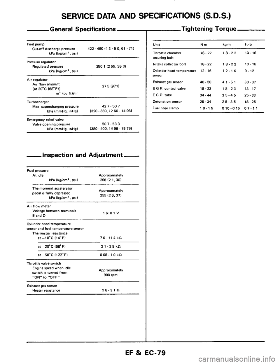
SERVICE DATA AND SPECIFICATIONS (S.D.S.)
General Specifications
Fuel pump Cut-off discharge pressure 422 -490 I4 3 -5 0.61 .71)
kPa (kg/cm'. psi1
Pressure regulator Regulated pressure 250 1 (2 55.36 3) kPa Ikalcm'. Dsll
Air regulatoi
27 5 (971 I Air flow amount
[atZO'C (68OF)I m3 (cu ft)/hr ~~
Turbocharger
Max supercharging pressure 42 7 - 507
kPa (mmHa.
InHal (320-380.1260-1496)
Emergency relief valve Valve opening pressure 507 - 53 3
(380 -400.14 96 - 15 75) kPa (mmHg, InHg)
-inspection and Adjustment -
Fuel pressure
At idle Approximately
kPa (kg/cm', psi) 206 (2 1.30)
The moment accelerator
pedal IS fully depressed Approximately
255 (2 6.371 kPa (kglcm'. psi)
Air flow meter
Voltage between terminals
B and D 1 620 1 V
Cylinder head temperature
sensor and fuel temperature sensor Thermistor resistance
at-lO'C 114'F) 7 0- 11 4 kSl
at 20'C I68'Fl 21-29kSl
at 50°C Il22'FI 068- 1 0 kSl ~~~~
Throttle
valve switch Engine speed when idle
swmh
IS turned from
"ON" to "OFF"
Approximately
900 rpm
Exhaust gas sensor Heater resistance 26-31Sl
- Tightening Torque
-
U"lt Nm kwn ft-lb
Throttle chamber 18-22 18-22 13-16 securing bolt
Intakecollector bolt
18-22 18-22 13-16
Cylinder head temperature 12. 16 1 2.1 6 9.12 SeIlSOr
Exhaust gar senior 40.50 41-51 30-37
E G R control valve 18-23 18-23 13-17
E G H tube 34-44 35-45 25-33
Detonation sensor 25.34 25-35 18-25
Fuel hose clamp 10-15 010-015 07-1 1
EF %i EC-79