NISSAN 350Z 2007 Z33 Body, Lock And Security System Workshop Manual
Manufacturer: NISSAN, Model Year: 2007,
Model line: 350Z,
Model: NISSAN 350Z 2007 Z33
Pages: 260, PDF Size: 11.8 MB
NISSAN 350Z 2007 Z33 Body, Lock And Security System Workshop Manual
350Z 2007 Z33
NISSAN
NISSAN
https://www.carmanualsonline.info/img/5/757/w960_757-0.png
NISSAN 350Z 2007 Z33 Body, Lock And Security System Workshop Manual
Trending: Fuse, audio, change key battery, light, mirror, spare wheel, receiver
Page 221 of 260
BODY REPAIR
BL-221
C
D
E
F
G
H
J
K
L
MA
B
BL
Revision: 2006 November2007 350Z
LOCATION OF PLASTIC PARTS (ROADSTER)
SIIA2361E
Page 222 of 260
BL-222
BODY REPAIR
Revision: 2006 November2007 350Z
SIIA2447E
Page 223 of 260
BODY REPAIR
BL-223
C
D
E
F
G
H
J
K
L
MA
B
BL
Revision: 2006 November2007 350Z
Precautions In Repairing High Strength SteelNIS00046
High strength steel is used for body panels in order to reduce vehicle weight.
Accordingly, precautions in repairing automotive bodies made of high strength steel are described below:
HIGH STRENGTH STEEL (HSS) USED IN NISSAN VEHICLES
SP130 is the most commonly used HSS.Tensile strength Nissan/Infiniti designation Major applicable parts
373 N/mm
2
(38kg/mm2 ,54klb/sq in)SP130
�Front & rear side member assembly
�Hoodledge assembly
�Upper dash
�Body side
�Other reinforcements
785-981 N/mm
2
(80-100kg/mm2 ,114-142klb/sq in)SP150�Front door guard beam
Page 224 of 260
 by heat-
in")
BL-224
BODY REPAIR
Revision: 2006 November2007 350Z
Read the following precautions when repairing HSS:
1. Additional points to consider
�The repair of reinforcements (such as side members) by heat-
ing is not recommended since it may weaken the component.
When heating is unavoidable, do not heat HSS parts above
550°C (1,022°F).
Verify heating temperature with a thermometer.
(Crayon-type and other similar type thermometer are appro-
priate.)
�When straightening body panels, use caution in pulling any
HSS panel. Because HSS is very strong, pulling may cause
deformation in adjacent portions of the body. In this case,
increase the number of measuring points, and carefully pull
the HSS panel.
�When cutting HSS panels, avoid gas (torch) cutting if possi-
ble. Instead, use a saw to avoid weakening surrounding areas
due to heat. If gas (torch) cutting is unavoidable, allow a mini-
mum margin of 50 mm (1.97in).
�When welding HSS panels, use spot welding whenever possi-
ble in order to minimize weakening surrounding areas due to
heat.
If spot welding is impossible, use M.I.G. welding. Do not use
gas (torch) welding because it is inferior in welding strength.
PIIA0115E
PIIA0116E
PIIA0117E
PIIA0144E
Page 225 of 260
BODY REPAIR
BL-225
C
D
E
F
G
H
J
K
L
MA
B
BL
Revision: 2006 November2007 350Z
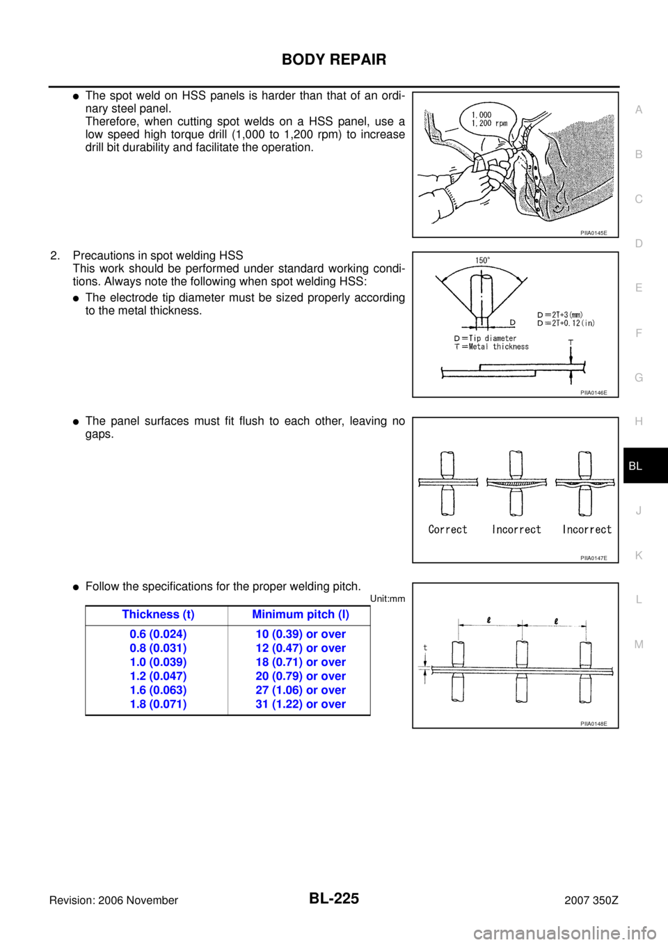
�The spot weld on HSS panels is harder than that of an ordi-
nary steel panel.
Therefore, when cutting spot welds on a HSS panel, use a
low speed high torque drill (1,000 to 1,200 rpm) to increase
drill bit durability and facilitate the operation.
2. Precautions in spot welding HSS
This work should be performed under standard working condi-
tions. Always note the following when spot welding HSS:
�The electrode tip diameter must be sized properly according
to the metal thickness.
�The panel surfaces must fit flush to each other, leaving no
gaps.
�Follow the specifications for the proper welding pitch.
Unit:mm
PIIA0145E
PIIA0146E
PIIA0147E
Thickness (t) Minimum pitch (l)
0.6 (0.024)
0.8 (0.031)
1.0 (0.039)
1.2 (0.047)
1.6 (0.063)
1.8 (0.071)10 (0.39) or over
12 (0.47) or over
18 (0.71) or over
20 (0.79) or over
27 (1.06) or over
31 (1.22) or over
PIIA0148E
Page 226 of 260
BL-226
BODY REPAIR
Revision: 2006 November2007 350Z
Replacement Operations (Coupe)NIS00047
DESCRIPTION
This section is prepared for technicians who have attained a high level of skill and experience in repairing col-
lision-damaged vehicles and also use modern service tools and equipment. Persons unfamiliar with body
repair techniques should not attempt to repair collision-damaged vehicles by using this section.
Technicians are also encouraged to read Body Repair Manual (Fundamentals) in order to ensure that the orig-
inal functions and quality of the vehicle can be maintained. The Body Repair Manual (Fundamentals) contains
additional information, including cautions and warning, that are not including in this manual. Technicians
should refer to both manuals to ensure proper repairs.
Please note that these information are prepared for worldwide usage, and as such, certain procedures might
not apply in some regions or countries.
Page 227 of 260
BODY REPAIR
BL-227
C
D
E
F
G
H
J
K
L
MA
B
BL
Revision: 2006 November2007 350Z
The symbols used in this section for cutting and welding / brazing operations are shown below.
PIIA0149E
Page 228 of 260

BL-228
BODY REPAIR
Revision: 2006 November2007 350Z
�Front pillar butt joint can be determined anywhere within shaded
area as shown in the figure. The best location for the butt joint is
at position A due to the construction of the vehicle. Refer to the
front pillar section.
�Determine cutting position and record distance from the locating
indent. Use this distance when cutting the service part. Cut outer
front pillar over 60 mm above inner front pillar cut position.
�Prepare a cutting jig to make outer pillar easier to cut. Also, this
will permit service part to be accurately cut at joint position.
�An example of cutting operation using a cutting jig is as follows.
1. Mark cutting lines.
A: Cut position of outer pillar
B: Cut position of inner pillar
2. Align cutting line with notch on jig. Clamp jig to pillar.
3. Cut outer pillar along groove of jig. (At position A)
4. Remove jig and cut remaining portions.
5. Cut inner pillar at position B in same manner.
PIIA0150E
PIIA0151E
PIIA0152E
PIIA0153E
Page 229 of 260
BODY REPAIR
BL-229
C
D
E
F
G
H
J
K
L
MA
B
BL
Revision: 2006 November2007 350Z
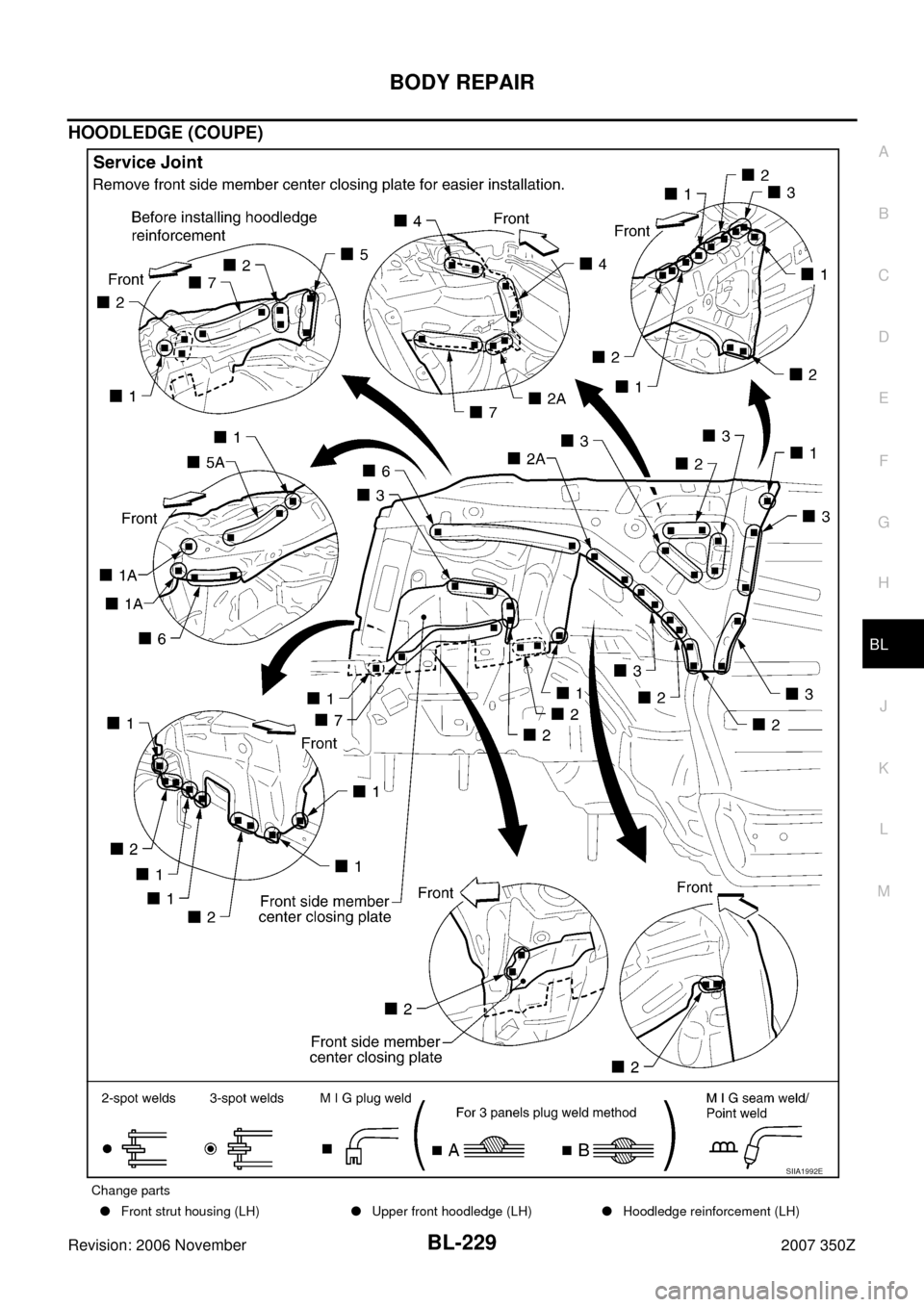
HOODLEDGE (COUPE)
Change parts
�Front strut housing (LH)�Upper front hoodledge (LH)�Hoodledge reinforcement (LH)
SIIA1992E
Page 230 of 260
BL-230
BODY REPAIR
Revision: 2006 November2007 350Z
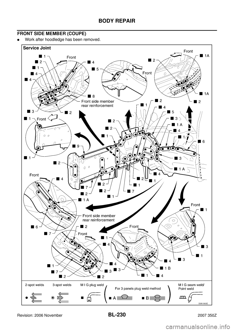
FRONT SIDE MEMBER (COUPE)
�Work after hoodledge has been removed.
SIIA1993E
Trending: mirror, length, spare tire, Reverse light, weight, roof, key

SIIA2361E")


NIS00047
DESCRIPTION
This section is prepared for technicians who have attained a high level of skill and experience i")