diagram NISSAN 350Z 2007 Z33 Engine Control Repair Manual
[x] Cancel search | Manufacturer: NISSAN, Model Year: 2007, Model line: 350Z, Model: NISSAN 350Z 2007 Z33Pages: 720
Page 301 of 720
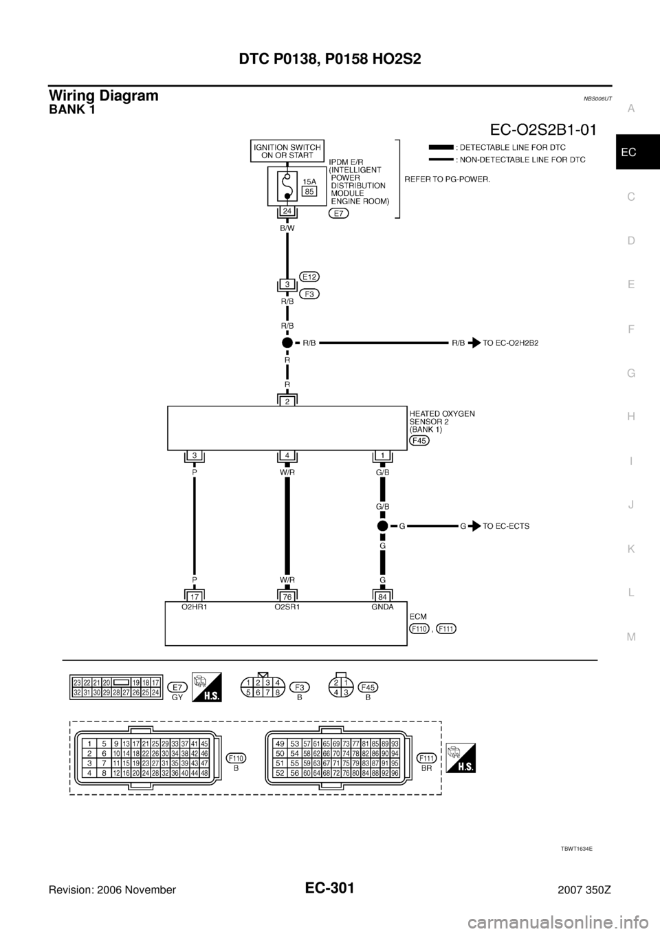
DTC P0138, P0158 HO2S2
EC-301
C
D
E
F
G
H
I
J
K
L
MA
EC
Revision: 2006 November2007 350Z
Wiring DiagramNBS006UT
BANK 1
TBWT1634E
Page 306 of 720
EC-306
DTC P0138, P0158 HO2S2
Revision: 2006 November2007 350Z
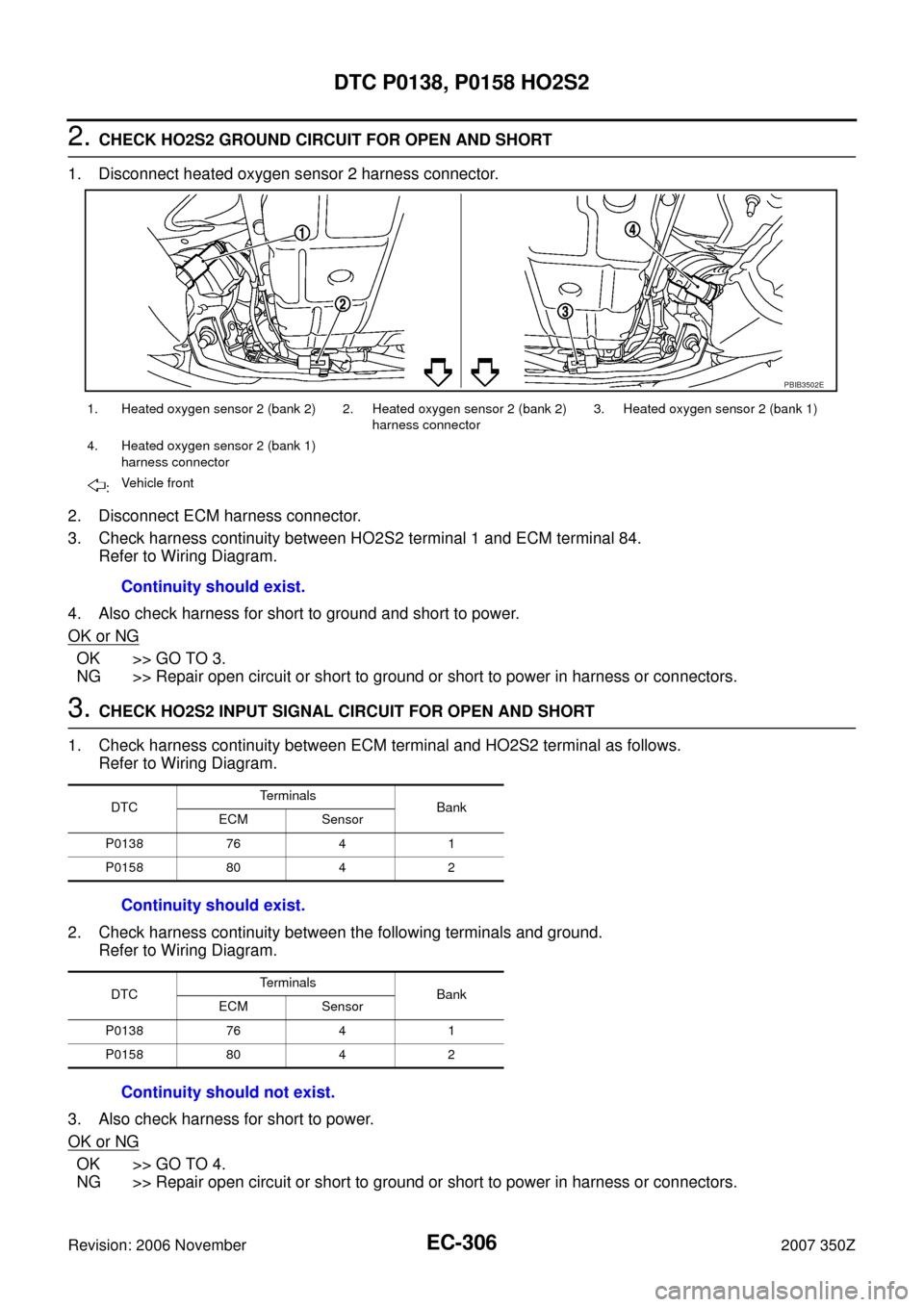
2. CHECK HO2S2 GROUND CIRCUIT FOR OPEN AND SHORT
1. Disconnect heated oxygen sensor 2 harness connector.
2. Disconnect ECM harness connector.
3. Check harness continuity between HO2S2 terminal 1 and ECM terminal 84.
Refer to Wiring Diagram.
4. Also check harness for short to ground and short to power.
OK or NG
OK >> GO TO 3.
NG >> Repair open circuit or short to ground or short to power in harness or connectors.
3. CHECK HO2S2 INPUT SIGNAL CIRCUIT FOR OPEN AND SHORT
1. Check harness continuity between ECM terminal and HO2S2 terminal as follows.
Refer to Wiring Diagram.
2. Check harness continuity between the following terminals and ground.
Refer to Wiring Diagram.
3. Also check harness for short to power.
OK or NG
OK >> GO TO 4.
NG >> Repair open circuit or short to ground or short to power in harness or connectors.
1. Heated oxygen sensor 2 (bank 2) 2. Heated oxygen sensor 2 (bank 2)
harness connector3. Heated oxygen sensor 2 (bank 1)
4. Heated oxygen sensor 2 (bank 1)
harness connector
:Vehicle front
Continuity should exist.
PBIB3502E
DTCTerminals
Bank
ECM Sensor
P0138 76 4 1
P0158 80 4 2
Continuity should exist.
DTCTerminals
Bank
ECM Sensor
P0138 76 4 1
P0158 80 4 2
Continuity should not exist.
Page 310 of 720
EC-310
DTC P0138, P0158 HO2S2
Revision: 2006 November2007 350Z
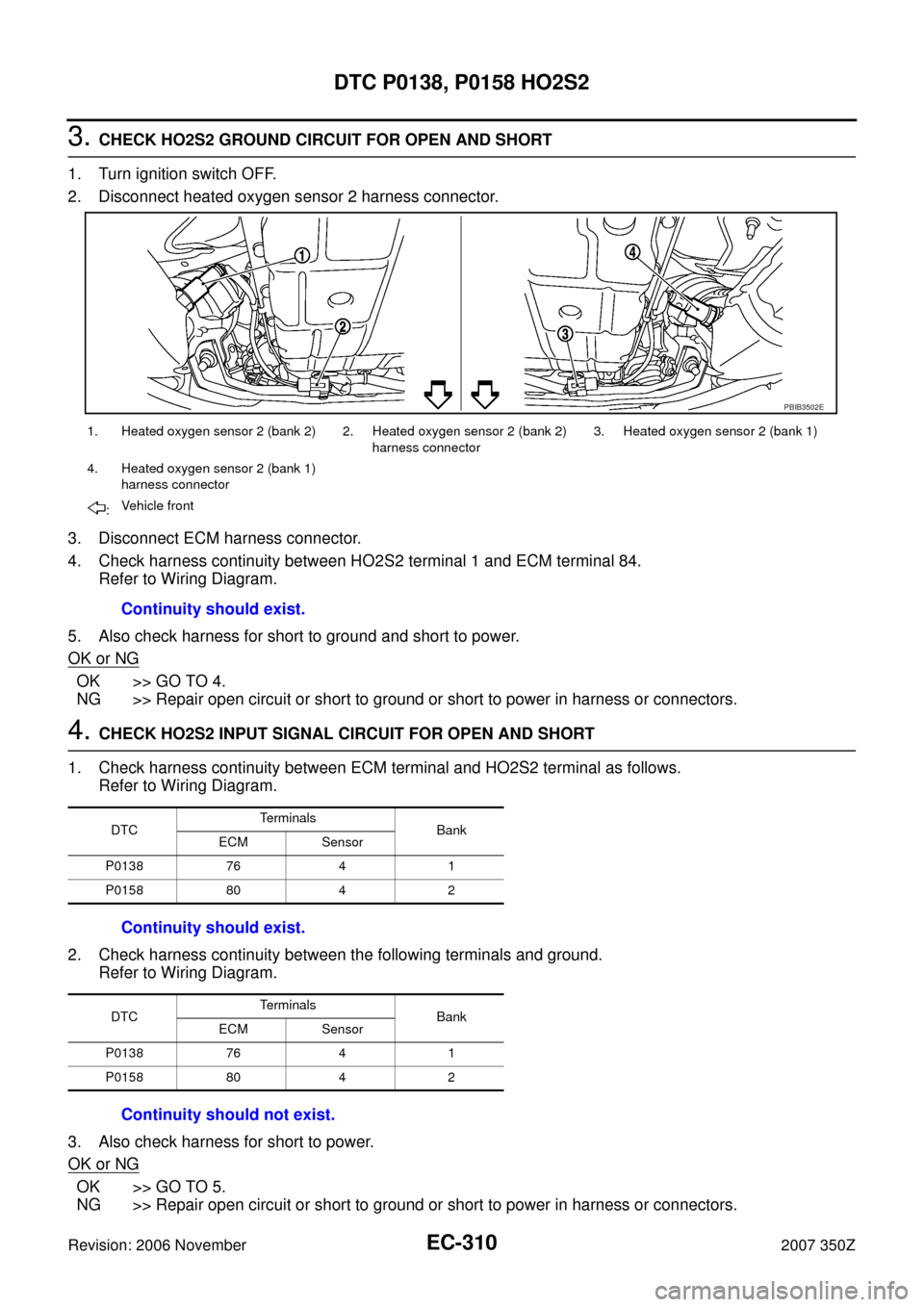
3. CHECK HO2S2 GROUND CIRCUIT FOR OPEN AND SHORT
1. Turn ignition switch OFF.
2. Disconnect heated oxygen sensor 2 harness connector.
3. Disconnect ECM harness connector.
4. Check harness continuity between HO2S2 terminal 1 and ECM terminal 84.
Refer to Wiring Diagram.
5. Also check harness for short to ground and short to power.
OK or NG
OK >> GO TO 4.
NG >> Repair open circuit or short to ground or short to power in harness or connectors.
4. CHECK HO2S2 INPUT SIGNAL CIRCUIT FOR OPEN AND SHORT
1. Check harness continuity between ECM terminal and HO2S2 terminal as follows.
Refer to Wiring Diagram.
2. Check harness continuity between the following terminals and ground.
Refer to Wiring Diagram.
3. Also check harness for short to power.
OK or NG
OK >> GO TO 5.
NG >> Repair open circuit or short to ground or short to power in harness or connectors.
1. Heated oxygen sensor 2 (bank 2) 2. Heated oxygen sensor 2 (bank 2)
harness connector3. Heated oxygen sensor 2 (bank 1)
4. Heated oxygen sensor 2 (bank 1)
harness connector
:Vehicle front
Continuity should exist.
PBIB3502E
DTCTerminals
Bank
ECM Sensor
P0138 76 4 1
P0158 80 4 2
Continuity should exist.
DTCTerminals
Bank
ECM Sensor
P0138 76 4 1
P0158 80 4 2
Continuity should not exist.
Page 315 of 720
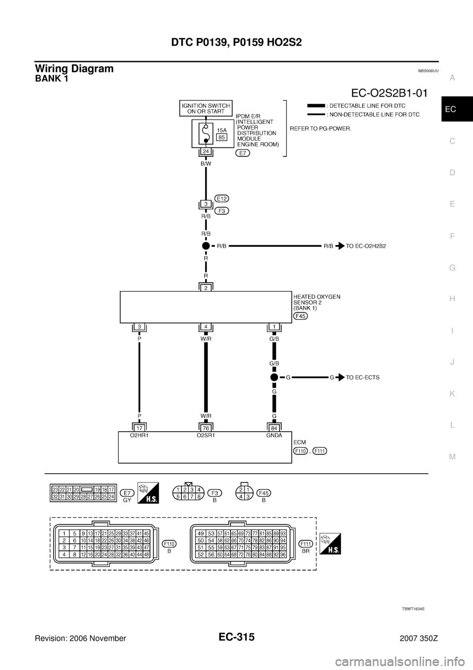
DTC P0139, P0159 HO2S2
EC-315
C
D
E
F
G
H
I
J
K
L
MA
EC
Revision: 2006 November2007 350Z
Wiring DiagramNBS006UU
BANK 1
TBWT1634E
Page 321 of 720
DTC P0139, P0159 HO2S2
EC-321
C
D
E
F
G
H
I
J
K
L
MA
EC
Revision: 2006 November2007 350Z
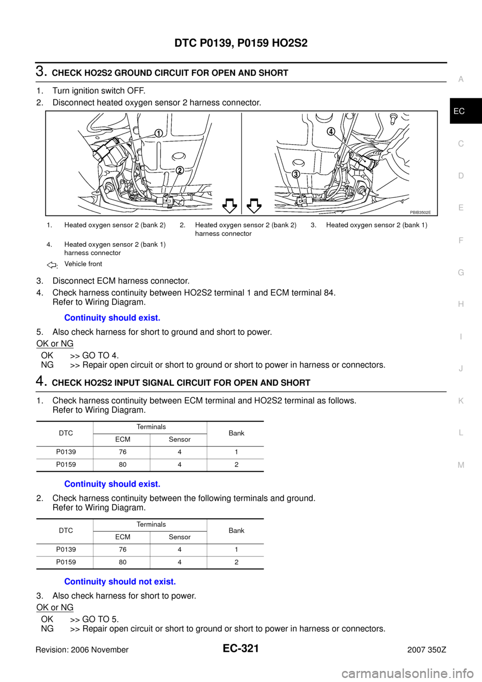
3. CHECK HO2S2 GROUND CIRCUIT FOR OPEN AND SHORT
1. Turn ignition switch OFF.
2. Disconnect heated oxygen sensor 2 harness connector.
3. Disconnect ECM harness connector.
4. Check harness continuity between HO2S2 terminal 1 and ECM terminal 84.
Refer to Wiring Diagram.
5. Also check harness for short to ground and short to power.
OK or NG
OK >> GO TO 4.
NG >> Repair open circuit or short to ground or short to power in harness or connectors.
4. CHECK HO2S2 INPUT SIGNAL CIRCUIT FOR OPEN AND SHORT
1. Check harness continuity between ECM terminal and HO2S2 terminal as follows.
Refer to Wiring Diagram.
2. Check harness continuity between the following terminals and ground.
Refer to Wiring Diagram.
3. Also check harness for short to power.
OK or NG
OK >> GO TO 5.
NG >> Repair open circuit or short to ground or short to power in harness or connectors.
1. Heated oxygen sensor 2 (bank 2) 2. Heated oxygen sensor 2 (bank 2)
harness connector3. Heated oxygen sensor 2 (bank 1)
4. Heated oxygen sensor 2 (bank 1)
harness connector
:Vehicle front
Continuity should exist.
PBIB3502E
DTCTe r m i n a l s
Bank
ECM Sensor
P0139 76 4 1
P0159 80 4 2
Continuity should exist.
DTCTe r m i n a l s
Bank
ECM Sensor
P0139 76 4 1
P0159 80 4 2
Continuity should not exist.
Page 326 of 720
EC-326
DTC P0171, P0174 FUEL INJECTION SYSTEM FUNCTION
Revision: 2006 November2007 350Z
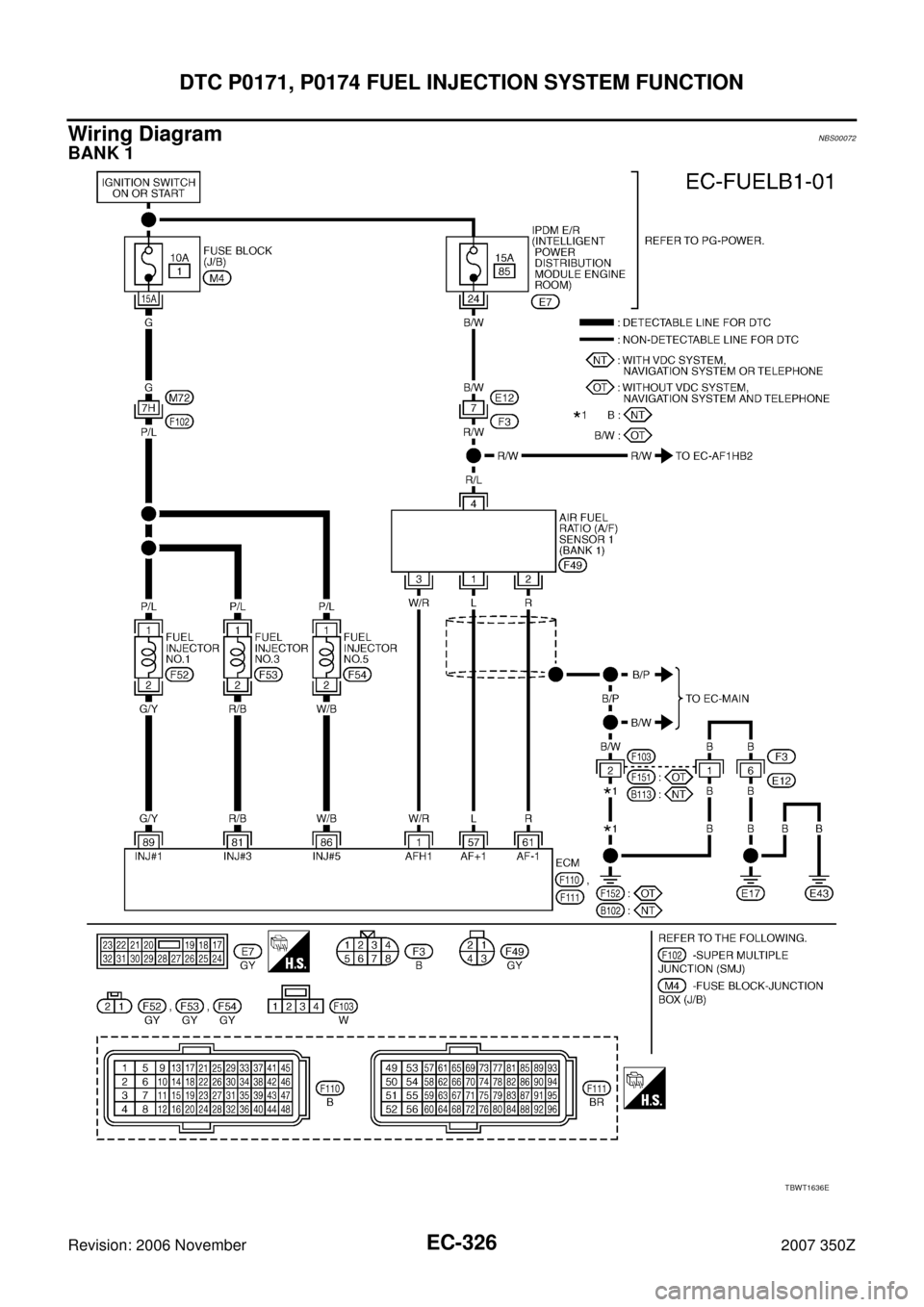
Wiring DiagramNBS00072
BANK 1
TBWT1636E
Page 331 of 720
DTC P0171, P0174 FUEL INJECTION SYSTEM FUNCTION
EC-331
C
D
E
F
G
H
I
J
K
L
MA
EC
Revision: 2006 November2007 350Z
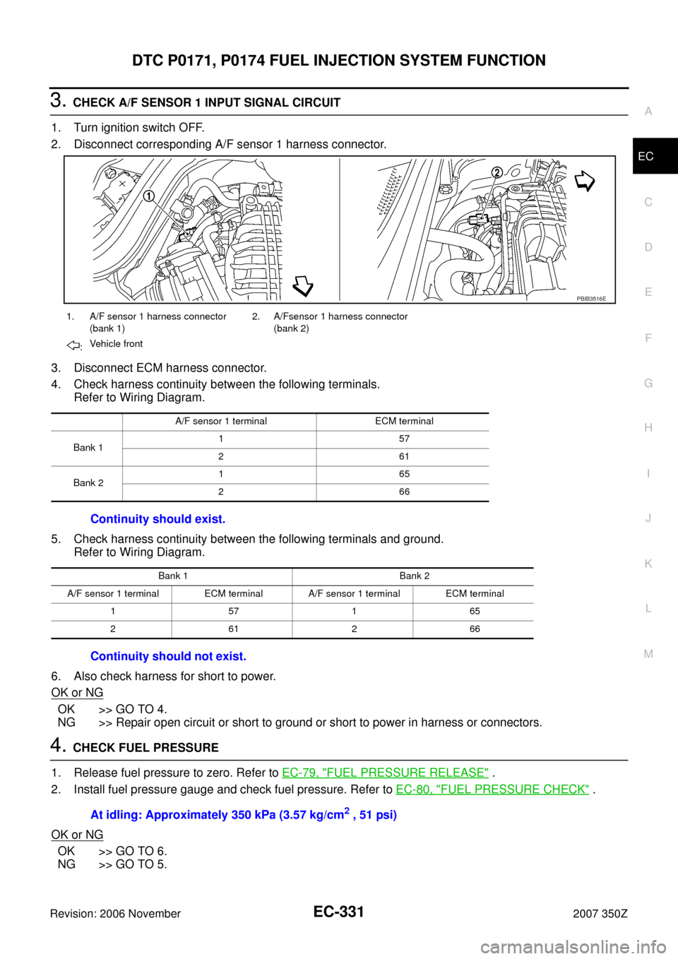
3. CHECK A/F SENSOR 1 INPUT SIGNAL CIRCUIT
1. Turn ignition switch OFF.
2. Disconnect corresponding A/F sensor 1 harness connector.
3. Disconnect ECM harness connector.
4. Check harness continuity between the following terminals.
Refer to Wiring Diagram.
5. Check harness continuity between the following terminals and ground.
Refer to Wiring Diagram.
6. Also check harness for short to power.
OK or NG
OK >> GO TO 4.
NG >> Repair open circuit or short to ground or short to power in harness or connectors.
4. CHECK FUEL PRESSURE
1. Release fuel pressure to zero. Refer to EC-79, "
FUEL PRESSURE RELEASE" .
2. Install fuel pressure gauge and check fuel pressure. Refer to EC-80, "
FUEL PRESSURE CHECK" .
OK or NG
OK >> GO TO 6.
NG >> GO TO 5.
1. A/F sensor 1 harness connector
(bank 1)2. A/Fsensor 1 harness connector
(bank 2)
:Vehicle front
A/F sensor 1 terminal ECM terminal
Bank 1157
261
Bank 2165
266
Continuity should exist.
Bank 1 Bank 2
A/F sensor 1 terminal ECM terminal A/F sensor 1 terminal ECM terminal
157165
261266
Continuity should not exist.
PBIB3516E
At idling: Approximately 350 kPa (3.57 kg/cm2 , 51 psi)
Page 336 of 720
EC-336
DTC P0172, P0175 FUEL INJECTION SYSTEM FUNCTION
Revision: 2006 November2007 350Z
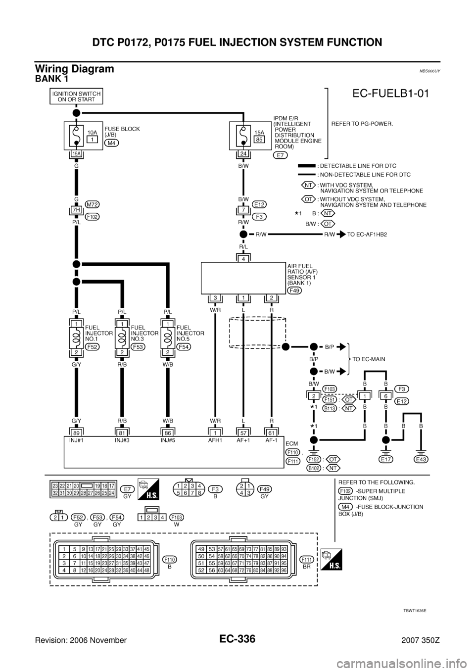
Wiring DiagramNBS006UY
BANK 1
TBWT1636E
Page 341 of 720
DTC P0172, P0175 FUEL INJECTION SYSTEM FUNCTION
EC-341
C
D
E
F
G
H
I
J
K
L
MA
EC
Revision: 2006 November2007 350Z
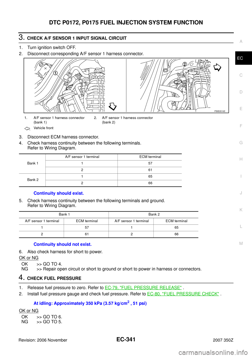
3. CHECK A/F SENSOR 1 INPUT SIGNAL CIRCUIT
1. Turn ignition switch OFF.
2. Disconnect corresponding A/F sensor 1 harness connector.
3. Disconnect ECM harness connector.
4. Check harness continuity between the following terminals.
Refer to Wiring Diagram.
5. Check harness continuity between the following terminals and ground.
Refer to Wiring Diagram.
6. Also check harness for short to power.
OK or NG
OK >> GO TO 4.
NG >> Repair open circuit or short to ground or short to power in harness or connectors.
4. CHECK FUEL PRESSURE
1. Release fuel pressure to zero. Refer to EC-79, "
FUEL PRESSURE RELEASE" .
2. Install fuel pressure gauge and check fuel pressure. Refer to EC-80, "
FUEL PRESSURE CHECK" .
OK or NG
OK >> GO TO 6.
NG >> GO TO 5.
1. A/F sensor 1 harness connector
(bank 1)2. A/F sensor 1 harness connector
(bank 2)
:Vehicle front
Bank 1A/F sensor 1 terminal ECM terminal
157
261
Bank 2165
266
Continuity should exist.
Bank 1 Bank 2
A/F sensor 1 terminal ECM terminal A/F sensor 1 terminal ECM terminal
157165
261266
Continuity should not exist.
PBIB3516E
At idling: Approximately 350 kPa (3.57 kg/cm2 , 51 psi)
Page 345 of 720
DTC P0181 FTT SENSOR
EC-345
C
D
E
F
G
H
I
J
K
L
MA
EC
Revision: 2006 November2007 350Z
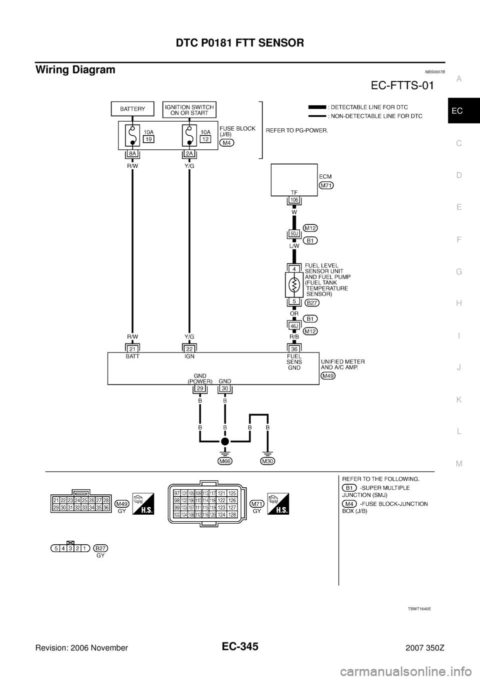
Wiring DiagramNBS0007B
TBWT1640E