NISSAN ALMERA 2001 Service Manual
ALMERA 2001
NISSAN
NISSAN
https://www.carmanualsonline.info/img/5/57348/w960_57348-0.png
NISSAN ALMERA 2001 Service Manual
Trending: child restraint, spark plugs replace, dimensions, wheel alignment, adding oil, lights, fuel cap release
Page 1711 of 2898
Meter/Gauge Operation and Odo/Trip Meter
Segment Check in Diagnosis Mode/Sedan
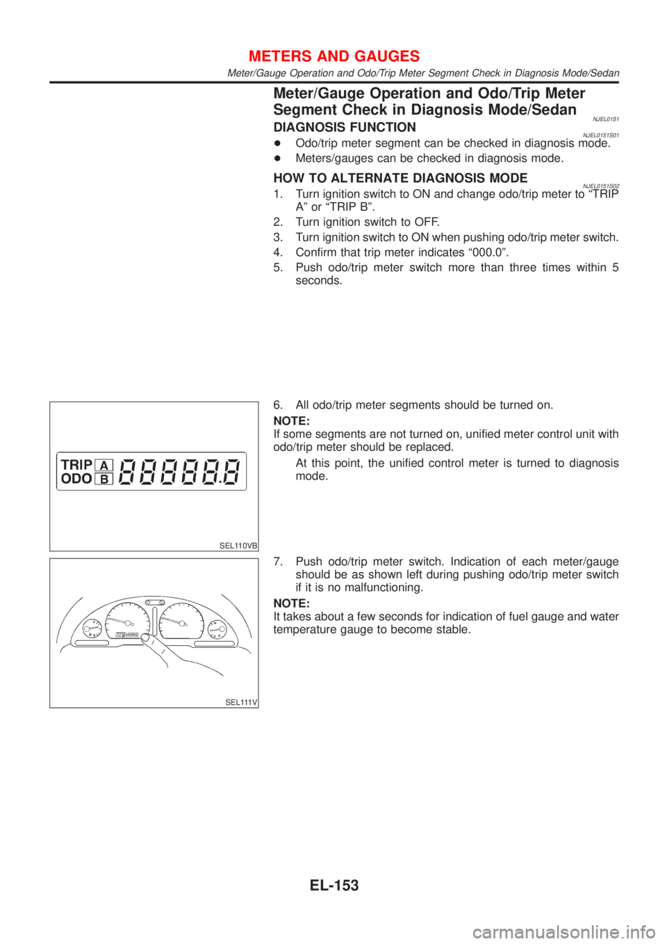
NJEL0151DIAGNOSIS FUNCTIONNJEL0151S01+Odo/trip meter segment can be checked in diagnosis mode.
+Meters/gauges can be checked in diagnosis mode.
HOW TO ALTERNATE DIAGNOSIS MODENJEL0151S021. Turn ignition switch to ON and change odo/trip meter to ªTRIP
Aº or ªTRIP Bº.
2. Turn ignition switch to OFF.
3. Turn ignition switch to ON when pushing odo/trip meter switch.
4. Confirm that trip meter indicates ª000.0º.
5. Push odo/trip meter switch more than three times within 5
seconds.
SEL110VB
6. All odo/trip meter segments should be turned on.
NOTE:
If some segments are not turned on, unified meter control unit with
odo/trip meter should be replaced.
At this point, the unified control meter is turned to diagnosis
mode.
SEL111V
7. Push odo/trip meter switch. Indication of each meter/gauge
should be as shown left during pushing odo/trip meter switch
if it is no malfunctioning.
NOTE:
It takes about a few seconds for indication of fuel gauge and water
temperature gauge to become stable.
METERS AND GAUGES
Meter/Gauge Operation and Odo/Trip Meter Segment Check in Diagnosis Mode/Sedan
EL-153
Page 1712 of 2898
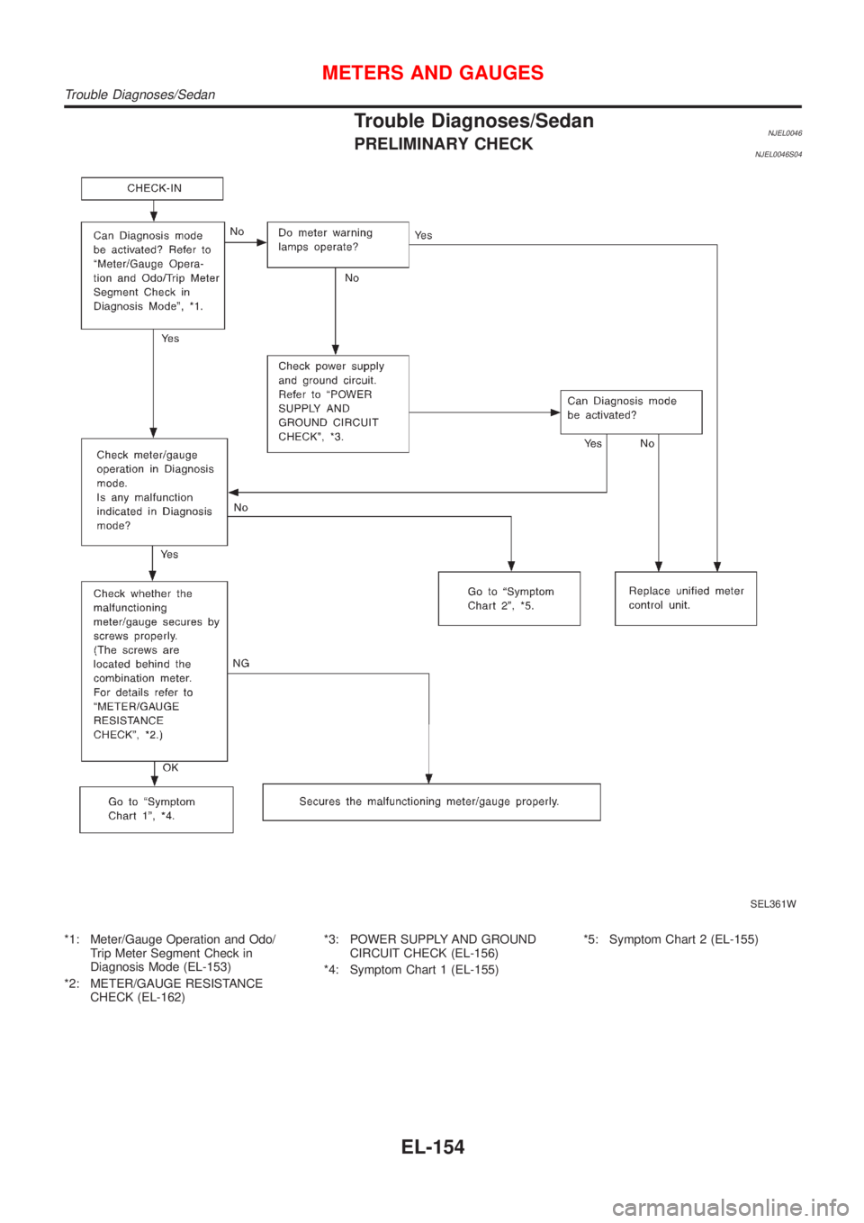
Trouble Diagnoses/SedanNJEL0046PRELIMINARY CHECKNJEL0046S04
SEL361W
*1: Meter/Gauge Operation and Odo/
Trip Meter Segment Check in
Diagnosis Mode (EL-153)
*2: METER/GAUGE RESISTANCE
CHECK (EL-162)*3: POWER SUPPLY AND GROUND
CIRCUIT CHECK (EL-156)
*4: Symptom Chart 1 (EL-155)*5: Symptom Chart 2 (EL-155)
METERS AND GAUGES
Trouble Diagnoses/Sedan
EL-154
Page 1713 of 2898
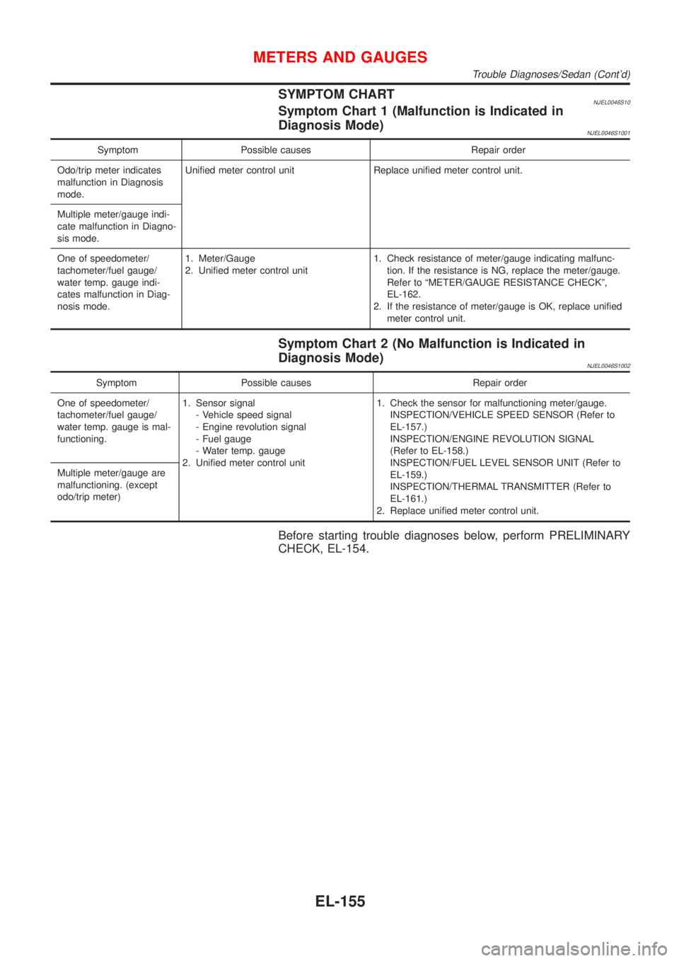
SYMPTOM CHARTNJEL0046S10Symptom Chart 1 (Malfunction is Indicated in
Diagnosis Mode)
NJEL0046S1001
Symptom Possible causes Repair order
Odo/trip meter indicates
malfunction in Diagnosis
mode.Unified meter control unit Replace unified meter control unit.
Multiple meter/gauge indi-
cate malfunction in Diagno-
sis mode.
One of speedometer/
tachometer/fuel gauge/
water temp. gauge indi-
cates malfunction in Diag-
nosis mode.1. Meter/Gauge
2. Unified meter control unit1. Check resistance of meter/gauge indicating malfunc-
tion. If the resistance is NG, replace the meter/gauge.
Refer to ªMETER/GAUGE RESISTANCE CHECKº,
EL-162.
2. If the resistance of meter/gauge is OK, replace unified
meter control unit.
Symptom Chart 2 (No Malfunction is Indicated in
Diagnosis Mode)
NJEL0046S1002
Symptom Possible causes Repair order
One of speedometer/
tachometer/fuel gauge/
water temp. gauge is mal-
functioning.1. Sensor signal
- Vehicle speed signal
- Engine revolution signal
- Fuel gauge
- Water temp. gauge
2. Unified meter control unit1. Check the sensor for malfunctioning meter/gauge.
INSPECTION/VEHICLE SPEED SENSOR (Refer to
EL-157.)
INSPECTION/ENGINE REVOLUTION SIGNAL
(Refer to EL-158.)
INSPECTION/FUEL LEVEL SENSOR UNIT (Refer to
EL-159.)
INSPECTION/THERMAL TRANSMITTER (Refer to
EL-161.)
2. Replace unified meter control unit. Multiple meter/gauge are
malfunctioning. (except
odo/trip meter)
Before starting trouble diagnoses below, perform PRELIMINARY
CHECK, EL-154.
METERS AND GAUGES
Trouble Diagnoses/Sedan (Cont'd)
EL-155
Page 1714 of 2898
SEL655X
POWER SUPPLY AND GROUND CIRCUIT CHECK=NJEL0046S07Power Supply Circuit CheckNJEL0046S0701
Terminals Ignition switch position
(+) (þ) OFF ACC ON
18 (with
tachometer)
or 21 (without
tachometer)GroundBattery
voltageBattery
voltageBattery
voltage
17 (with
tachometer)
or 22 (without
tachometer)Ground 0V 0VBattery
voltage
If NG, check the following.
+10A fuse [No. 12, located in fuse block (J/B)]
+10A fuse [No. 30, located in fuse block (J/B)]
+Harness for open or short between fuse and combination
meter
SEL656X
Ground Circuit CheckNJEL0046S0702
Terminals Continuity
24 - Ground (with tachometer) or 23 -
Ground (without tachometer)Ye s
METERS AND GAUGES
Trouble Diagnoses/Sedan (Cont'd)
EL-156
Page 1715 of 2898
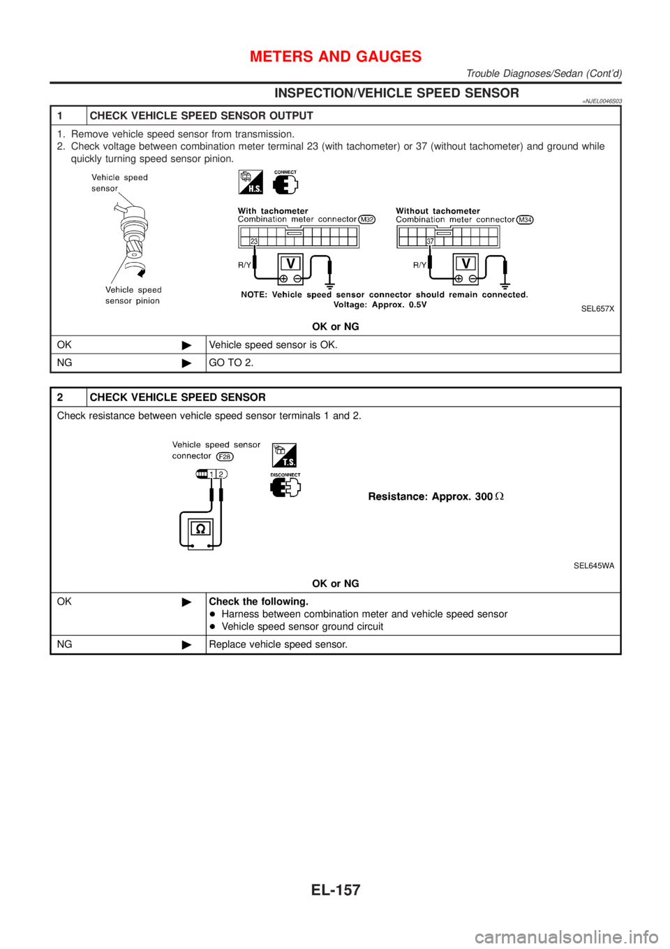
INSPECTION/VEHICLE SPEED SENSOR=NJEL0046S03
1 CHECK VEHICLE SPEED SENSOR OUTPUT
1. Remove vehicle speed sensor from transmission.
2. Check voltage between combination meter terminal 23 (with tachometer) or 37 (without tachometer) and ground while
quickly turning speed sensor pinion.
SEL657X
OK or NG
OK©Vehicle speed sensor is OK.
NG©GO TO 2.
2 CHECK VEHICLE SPEED SENSOR
Check resistance between vehicle speed sensor terminals 1 and 2.
SEL645WA
OK or NG
OK©Check the following.
+Harness between combination meter and vehicle speed sensor
+Vehicle speed sensor ground circuit
NG©Replace vehicle speed sensor.
METERS AND GAUGES
Trouble Diagnoses/Sedan (Cont'd)
EL-157
Page 1716 of 2898
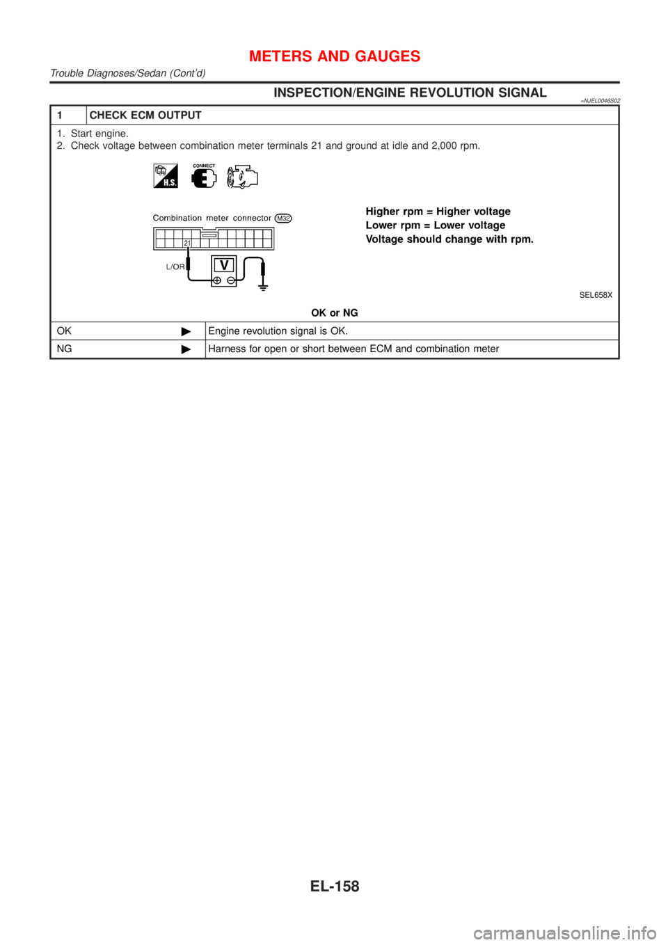
INSPECTION/ENGINE REVOLUTION SIGNAL=NJEL0046S02
1 CHECK ECM OUTPUT
1. Start engine.
2. Check voltage between combination meter terminals 21 and ground at idle and 2,000 rpm.
SEL658X
OK or NG
OK©Engine revolution signal is OK.
NG©Harness for open or short between ECM and combination meter
METERS AND GAUGES
Trouble Diagnoses/Sedan (Cont'd)
EL-158
Page 1717 of 2898
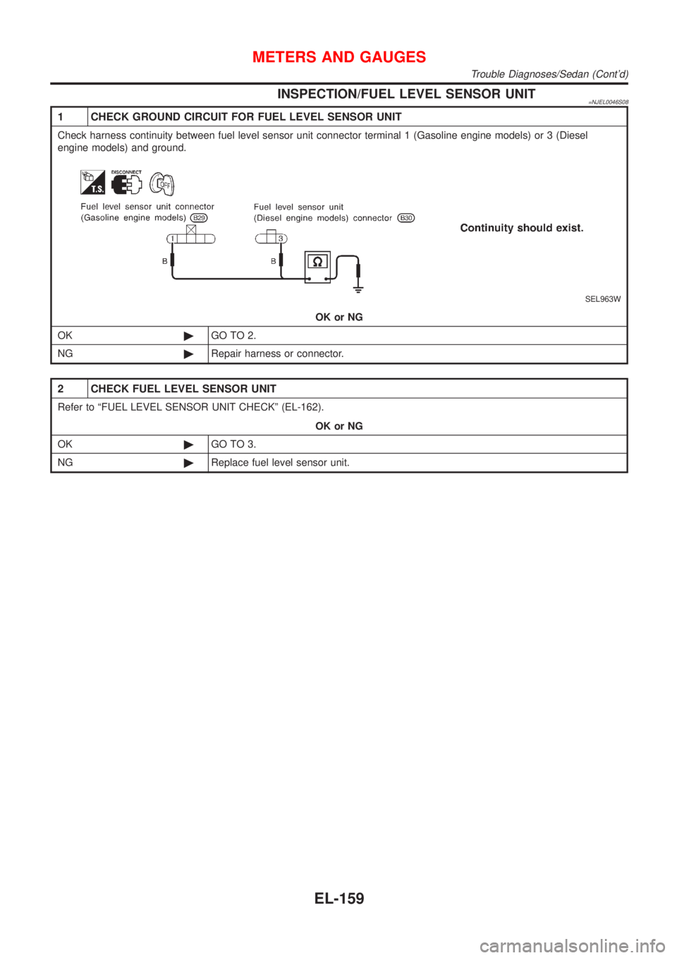
INSPECTION/FUEL LEVEL SENSOR UNIT=NJEL0046S08
1 CHECK GROUND CIRCUIT FOR FUEL LEVEL SENSOR UNIT
Check harness continuity between fuel level sensor unit connector terminal 1 (Gasoline engine models) or 3 (Diesel
engine models) and ground.
SEL963W
OK or NG
OK©GO TO 2.
NG©Repair harness or connector.
2 CHECK FUEL LEVEL SENSOR UNIT
Refer to ªFUEL LEVEL SENSOR UNIT CHECKº (EL-162).
OK or NG
OK©GO TO 3.
NG©Replace fuel level sensor unit.
METERS AND GAUGES
Trouble Diagnoses/Sedan (Cont'd)
EL-159
Page 1718 of 2898
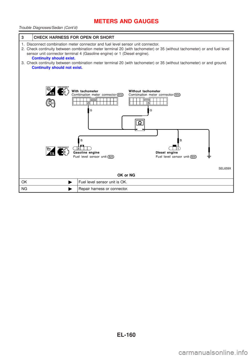
3 CHECK HARNESS FOR OPEN OR SHORT
1. Disconnect combination meter connector and fuel level sensor unit connector.
2. Check continuity between combination meter terminal 20 (with tachometer) or 35 (without tachometer) or and fuel level
sensor unit connector terminal 4 (Gasoline engine) or 1 (Diesel engine).
Continuity should exist.
3. Check continuity between combination meter terminal 20 (with tachometer) or 35 (without tachometer) or and ground.
Continuity should not exist.
SEL659X
OK or NG
OK©Fuel level sensor unit is OK.
NG©Repair harness or connector.
METERS AND GAUGES
Trouble Diagnoses/Sedan (Cont'd)
EL-160
Page 1719 of 2898
INSPECTION/THERMAL TRANSMITTER=NJEL0046S09
1 CHECK THERMAL TRANSMITTER
Refer to ªTHERMAL TRANSMITTER CHECKº (EL-163).
OK or NG
OK©GO TO 2.
NG©Replace.
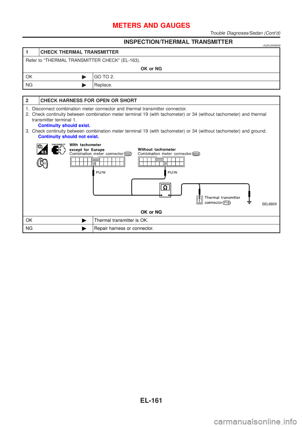
2 CHECK HARNESS FOR OPEN OR SHORT
1. Disconnect combination meter connector and thermal transmitter connector.
2. Check continuity between combination meter terminal 19 (with tachometer) or 34 (without tachometer) and thermal
transmitter terminal 1.
Continuity should exist.
3. Check continuity between combination meter terminal 19 (with tachometer) or 34 (without tachometer) and ground.
Continuity should not exist.
SEL660X
OK or NG
OK©Thermal transmitter is OK.
NG©Repair harness or connector.
METERS AND GAUGES
Trouble Diagnoses/Sedan (Cont'd)
EL-161
Page 1720 of 2898
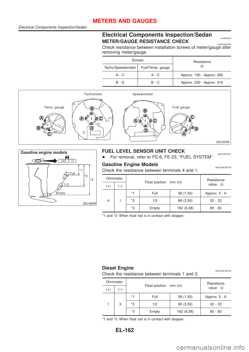
Electrical Components Inspection/Sedan=NJEL0047METER/GAUGE RESISTANCE CHECKNJEL0047S04Check resistance between installation screws of meter/gauge after
removing meter/gauge.
Screws
Resistance
W
Tacho/Speedometer Fuel/Temp. gauge
A - C A - C Approx. 190 - Approx. 260
B - D B - C Approx. 230 - Approx. 310
SEL933W
SEL962W
FUEL LEVEL SENSOR UNIT CHECKNJEL0047S01+For removal, refer to FE-6, FE-23, ªFUEL SYSTEMº.
Gasoline Engine ModelsNJEL0047S0103Check the resistance between terminals 4 and 1.
Ohmmeter
Float position mm (in)Resistance
valueW
(+) (þ)
41*1 Full 38 (1.50) Approx.5-6
*2 1/2 89 (3.50) 32 - 33
*3 Empty 162 (6.38) 80 - 83
*1 and *3: When float rod is in contact with stopper.
Diesel EngineNJEL0047S0104Check the resistance between terminals 1 and 3.
Ohmmeter
Float position mm (in)Resistance
valueW
(+) (þ)
13*1 Full 38 (1.50) Approx.5-6
*2 1/2 90 (3.50) 32 - 33
*3 Empty 162 (6.38) 80 - 83
*1 and *3: When float rod is in contact with stopper.
METERS AND GAUGES
Electrical Components Inspection/Sedan
EL-162
Trending: light, coolant temperature, brakes, coolant level, tow, jump start terminals, transmission oil

