NISSAN ALMERA 2001 Service Manual
ALMERA 2001
NISSAN
NISSAN
https://www.carmanualsonline.info/img/5/57348/w960_57348-0.png
NISSAN ALMERA 2001 Service Manual
Trending: display, jacking points, check oil, tires, bulb, tire size, sat nav
Page 2441 of 2898
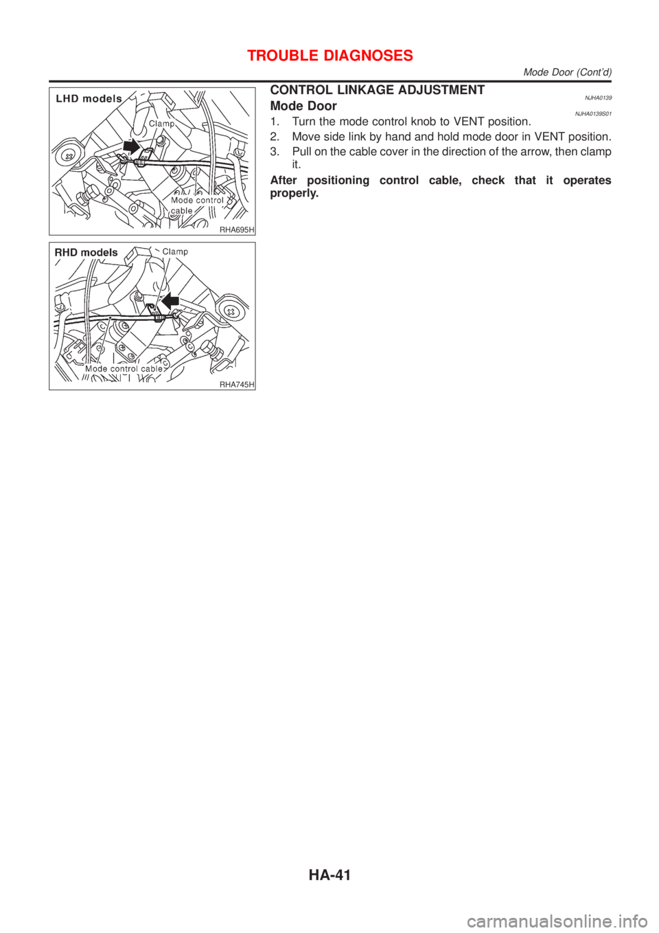
RHA695H
RHA745H
CONTROL LINKAGE ADJUSTMENTNJHA0139Mode DoorNJHA0139S011. Turn the mode control knob to VENT position.
2. Move side link by hand and hold mode door in VENT position.
3. Pull on the cable cover in the direction of the arrow, then clamp
it.
After positioning control cable, check that it operates
properly.
TROUBLE DIAGNOSES
Mode Door (Cont'd)
HA-41
Page 2442 of 2898
Air Mix Door
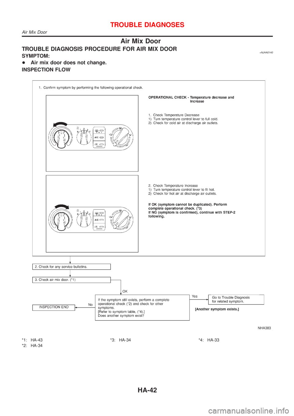
TROUBLE DIAGNOSIS PROCEDURE FOR AIR MIX DOOR=NJHA0140SYMPTOM:
+Air mix door does not change.
INSPECTION FLOW
NHA383
*1: HA-43
*2: HA-34*3: HA-34 *4: HA-33
TROUBLE DIAGNOSES
Air Mix Door
HA-42
Page 2443 of 2898
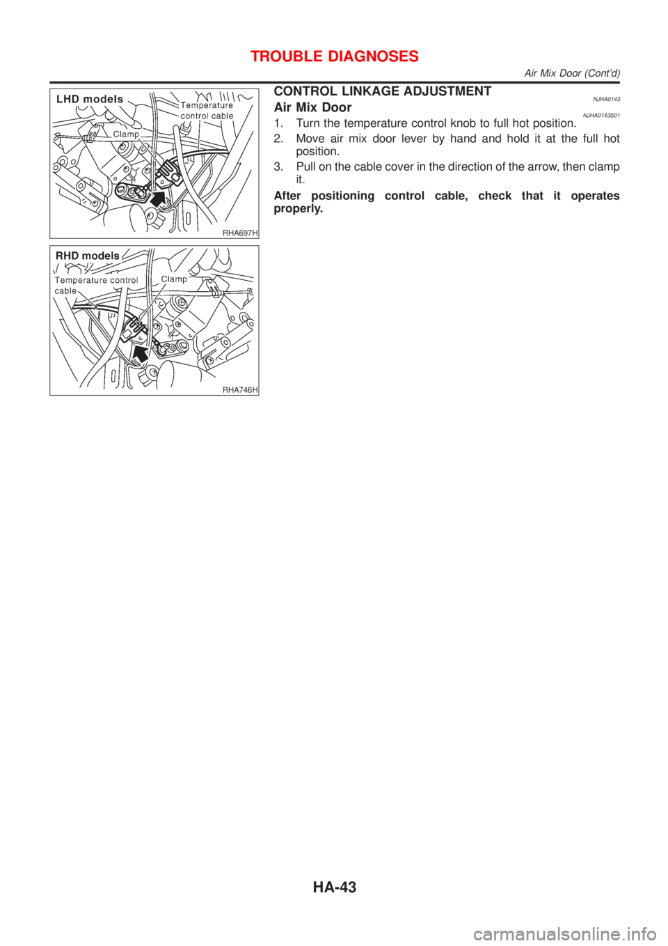
RHA697H
RHA746H
CONTROL LINKAGE ADJUSTMENTNJHA0143Air Mix DoorNJHA0143S011. Turn the temperature control knob to full hot position.
2. Move air mix door lever by hand and hold it at the full hot
position.
3. Pull on the cable cover in the direction of the arrow, then clamp
it.
After positioning control cable, check that it operates
properly.
TROUBLE DIAGNOSES
Air Mix Door (Cont'd)
HA-43
Page 2444 of 2898
Max Hot Door (For Scandinavia and Cold Spec
Models)
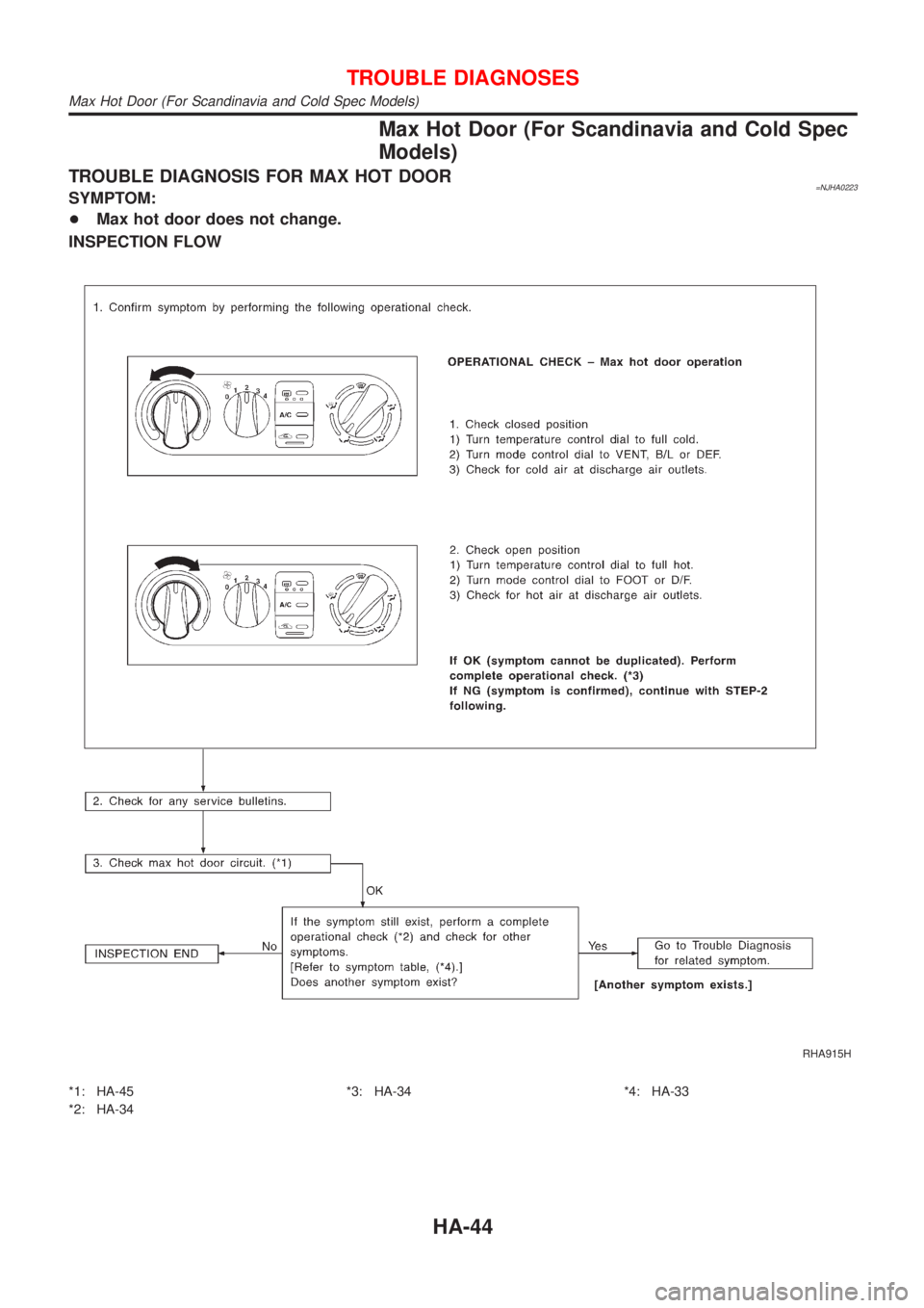
TROUBLE DIAGNOSIS FOR MAX HOT DOOR=NJHA0223SYMPTOM:
+Max hot door does not change.
INSPECTION FLOW
RHA915H
*1: HA-45
*2: HA-34*3: HA-34 *4: HA-33
TROUBLE DIAGNOSES
Max Hot Door (For Scandinavia and Cold Spec Models)
HA-44
Page 2445 of 2898
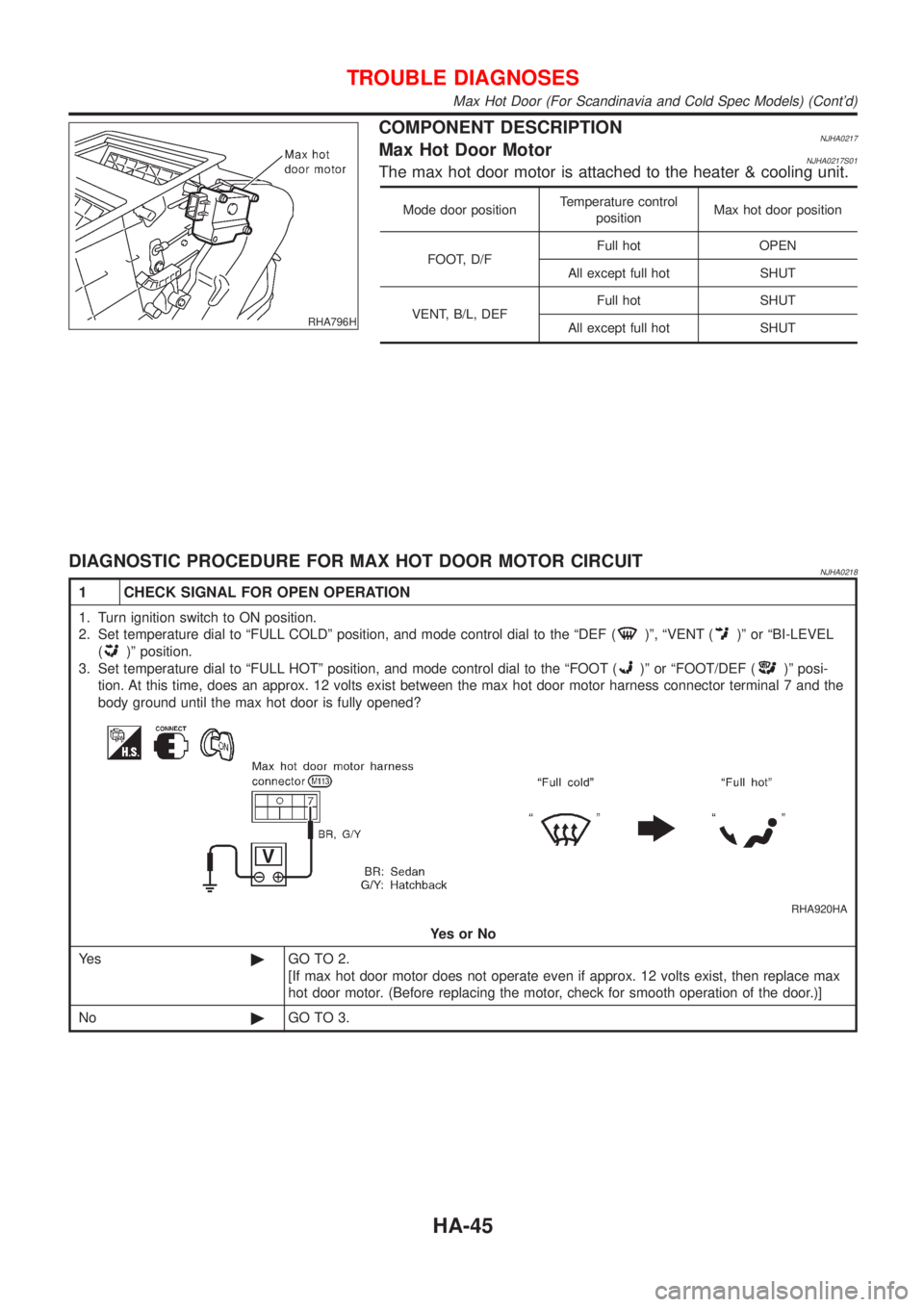
RHA796H
COMPONENT DESCRIPTIONNJHA0217Max Hot Door MotorNJHA0217S01The max hot door motor is attached to the heater & cooling unit.
Mode door positionTemperature control
positionMax hot door position
FOOT, D/FFull hot OPEN
All except full hot SHUT
VENT, B/L, DEFFull hot SHUT
All except full hot SHUT
DIAGNOSTIC PROCEDURE FOR MAX HOT DOOR MOTOR CIRCUITNJHA0218
1 CHECK SIGNAL FOR OPEN OPERATION
1. Turn ignition switch to ON position.
2. Set temperature dial to ªFULL COLDº position, and mode control dial to the ªDEF (
)º, ªVENT ()º or ªBI-LEVEL
(
)º position.
3. Set temperature dial to ªFULL HOTº position, and mode control dial to the ªFOOT (
)º or ªFOOT/DEF ()º posi-
tion. At this time, does an approx. 12 volts exist between the max hot door motor harness connector terminal 7 and the
body ground until the max hot door is fully opened?
RHA920HA
YesorNo
Ye s©GO TO 2.
[If max hot door motor does not operate even if approx. 12 volts exist, then replace max
hot door motor. (Before replacing the motor, check for smooth operation of the door.)]
No©GO TO 3.
TROUBLE DIAGNOSES
Max Hot Door (For Scandinavia and Cold Spec Models) (Cont'd)
HA-45
Page 2446 of 2898
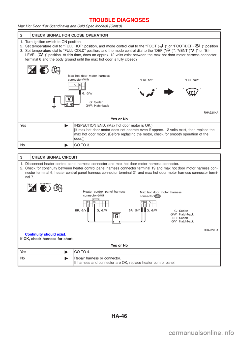
2 CHECK SIGNAL FOR CLOSE OPERATION
1. Turn ignition switch to ON position.
2. Set temperature dial to ªFULL HOTº position, and mode control dial to the ªFOOT (
)º or ªFOOT/DEF ()º position
3. Set temperature dial to ªFULL COLDº position, and the mode control dial to the ªDEF (
)º, ªVENT ()º or ªBI-
LEVEL (
)º position. At this time, does an approx. 12 volts exist between the max hot door motor harness connector
terminal 6 and the body ground until the max hot door is fully closed?
RHA921HA
YesorNo
Ye s©INSPECTION END. (Max hot door motor is OK.)
[If max hot door motor does not operate even if approx. 12 volts exist, then replace the
max hot door motor. (Before replacing the motor, check for smooth operation of the
door.)]
No©GO TO 3.
3 CHECK SIGNAL CIRCUIT
1. Disconnect heater control panel harness connector and max hot door motor harness connector.
2. Check for continuity between heater control panel harness connector terminal 19 and max hot door motor harness con-
nector terminal 6, heater control panel harness connector terminal 21 and max hot door motor harness connector termi-
nal 7.
RHA922HA
Continuity should exist.
If OK, check harness for short.
YesorNo
Ye s©GO TO 4.
No©Repair harness or connector.
If harness and connector are OK, replace heater control panel.
TROUBLE DIAGNOSES
Max Hot Door (For Scandinavia and Cold Spec Models) (Cont'd)
HA-46
Page 2447 of 2898
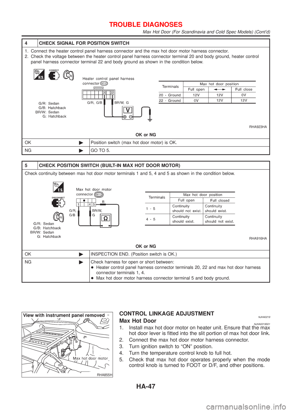
4 CHECK SIGNAL FOR POSITION SWITCH
1. Connect the heater control panel harness connector and the max hot door motor harness connector.
2. Check the voltage between the heater control panel harness connector terminal 20 and body ground, heater control
panel harness connector terminal 22 and body ground as shown in the condition below.
RHA923HA
OK or NG
OK©Position switch (max hot door motor) is OK.
NG©GO TO 5.
5 CHECK POSITION SWITCH (BUILT-IN MAX HOT DOOR MOTOR)
Check continuity between max hot door motor terminals 1 and 5, 4 and 5 as shown in the condition below.
RHA916HA
OK or NG
OK©INSPECTION END. (Position switch is OK.)
NG©Check harness for open or short between:
+Heater control panel harness connector terminals 20, 22 and max hot door harness
connector terminals 1, 4.
+Max hot door motor harness connector terminal 5 and body ground.
RHA855H
CONTROL LINKAGE ADJUSTMENTNJHA0219Max Hot DoorNJHA0219S011. Install max hot door motor on heater unit. Ensure that the max
hot door lever is fitted into the slit portion of max hot door link.
2. Connect the max hot door motor harness connector.
3. Turn ignition switch to ªONº position.
4. Turn the temperature control knob to full hot.
5. Check that max hot door operates properly when the mode
control knob is turned to FOOT or D/F, and other positions.
TROUBLE DIAGNOSES
Max Hot Door (For Scandinavia and Cold Spec Models) (Cont'd)
HA-47
Page 2448 of 2898
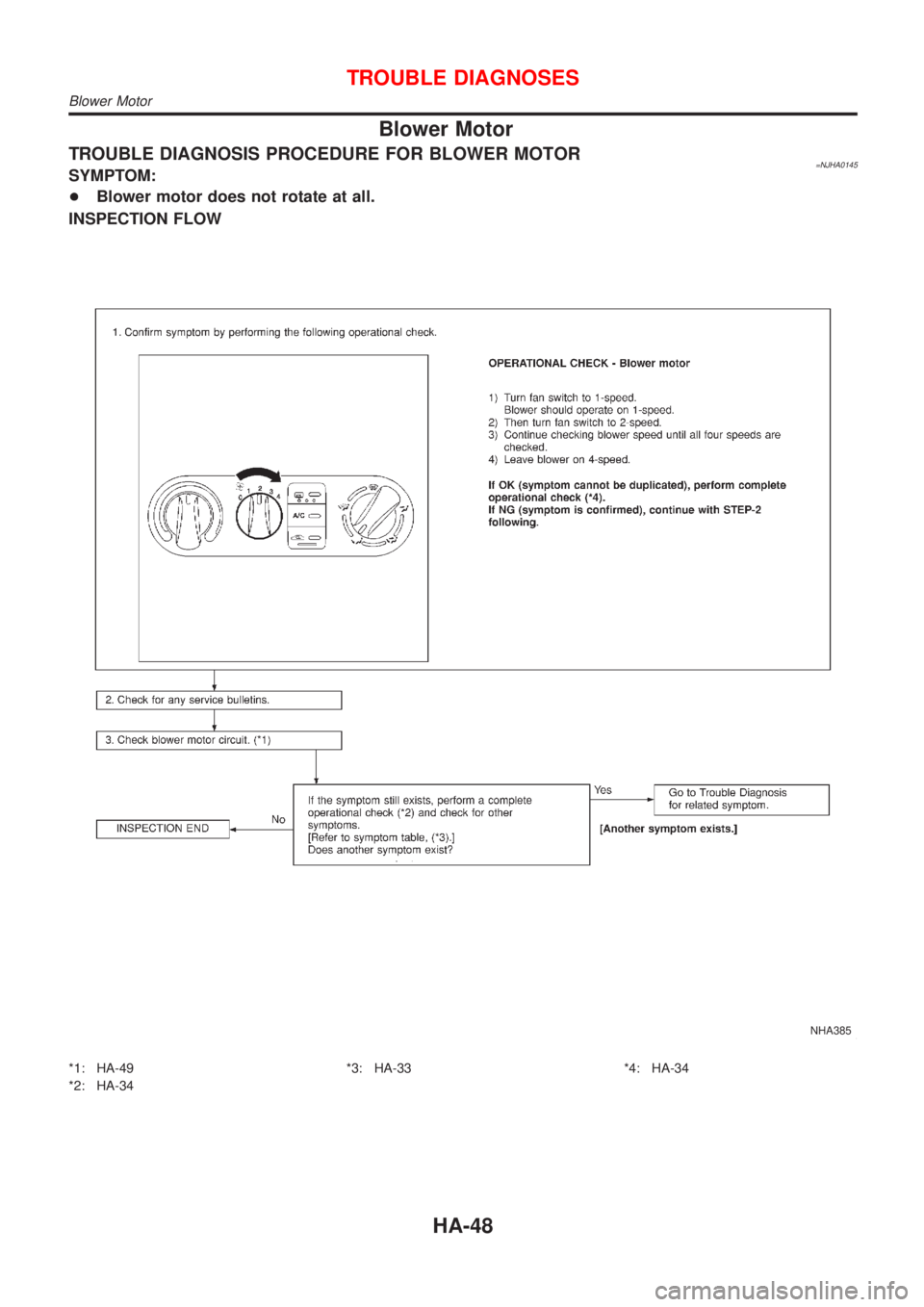
Blower Motor
TROUBLE DIAGNOSIS PROCEDURE FOR BLOWER MOTOR=NJHA0145SYMPTOM:
+Blower motor does not rotate at all.
INSPECTION FLOW
NHA385
*1: HA-49
*2: HA-34*3: HA-33 *4: HA-34
TROUBLE DIAGNOSES
Blower Motor
HA-48
Page 2449 of 2898
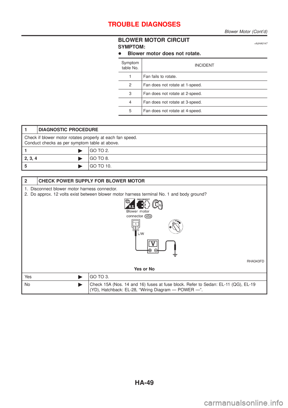
BLOWER MOTOR CIRCUIT=NJHA0147SYMPTOM:
+Blower motor does not rotate.
Symptom
table No.INCIDENT
1 Fan fails to rotate.
2 Fan does not rotate at 1-speed.
3 Fan does not rotate at 2-speed.
4 Fan does not rotate at 3-speed.
5 Fan does not rotate at 4-speed.
1 DIAGNOSTIC PROCEDURE
Check if blower motor rotates properly at each fan speed.
Conduct checks as per symptom table at above.
1©GO TO 2.
2, 3, 4©GO TO 8.
5©GO TO 10.
2 CHECK POWER SUPPLY FOR BLOWER MOTOR
1. Disconnect blower motor harness connector.
2. Do approx. 12 volts exist between blower motor harness terminal No. 1 and body ground?
RHA343FD
YesorNo
Ye s©GO TO 3.
No©Check 15A (Nos. 14 and 16) fuses at fuse block. Refer to Sedan: EL-11 (QG), EL-19
(YD), Hatchback: EL-28, ªWiring Diagram Ð POWER к.
TROUBLE DIAGNOSES
Blower Motor (Cont'd)
HA-49
Page 2450 of 2898
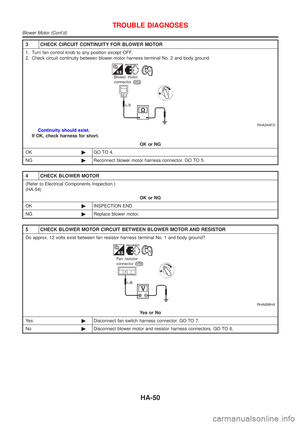
3 CHECK CIRCUIT CONTINUITY FOR BLOWER MOTOR
1. Turn fan control knob to any position except OFF.
2. Check circuit continuity between blower motor harness terminal No. 2 and body ground.
RHA344FD
Continuity should exist.
If OK, check harness for short.
OK or NG
OK©GO TO 4.
NG©Reconnect blower motor harness connector. GO TO 5.
4 CHECK BLOWER MOTOR
(Refer to Electrical Components Inspection.)
(HA-54)
OK or NG
OK©INSPECTION END
NG©Replace blower motor.
5 CHECK BLOWER MOTOR CIRCUIT BETWEEN BLOWER MOTOR AND RESISTOR
Do approx. 12 volts exist between fan resistor harness terminal No. 1 and body ground?
RHA699HA
YesorNo
Ye s©Disconnect fan switch harness connector. GO TO 7.
No©Disconnect blower motor and resistor harness connectors. GO TO 6.
TROUBLE DIAGNOSES
Blower Motor (Cont'd)
HA-50
Trending: child seat, brake fluid, spark plugs, alternator, instrument panel, towing, high beam
