NISSAN ALMERA 2001 Service Manual
Manufacturer: NISSAN, Model Year: 2001, Model line: ALMERA, Model: NISSAN ALMERA 2001Pages: 2898, PDF Size: 60.76 MB
Page 721 of 2898
![NISSAN ALMERA 2001 Service Manual +Clean old grease and abrasive materials off the grease
application area.
SCL815
NOTE:
+Equally apply a coat [approximately 1 mm (0.04 in) thick] of
clutch sleeve grease to withdrawal lever and holder NISSAN ALMERA 2001 Service Manual +Clean old grease and abrasive materials off the grease
application area.
SCL815
NOTE:
+Equally apply a coat [approximately 1 mm (0.04 in) thick] of
clutch sleeve grease to withdrawal lever and holder](/img/5/57348/w960_57348-720.png)
+Clean old grease and abrasive materials off the grease
application area.
SCL815
NOTE:
+Equally apply a coat [approximately 1 mm (0.04 in) thick] of
clutch sleeve grease to withdrawal lever and holder spring
frictional surfaces.
+Apply a coat of clutch sleeve grease to the grooves on contact
surfaces of the withdrawal lever ball pin and inner surface of
release bearing so that grease application, make sure that
grease is flush with grooves.
+Equally apply a thin coat of clutch sleeve grease to release
bearing frictional surface. After grease application, install
release bearing. Wipe off excess grease forced out during
bearing installation. Remove release bearing.
2. Installation is in the reverse order of removal.
CLUTCH RELEASE MECHANISMRS5F50A
Installation (Cont'd)
CL-21
Page 722 of 2898
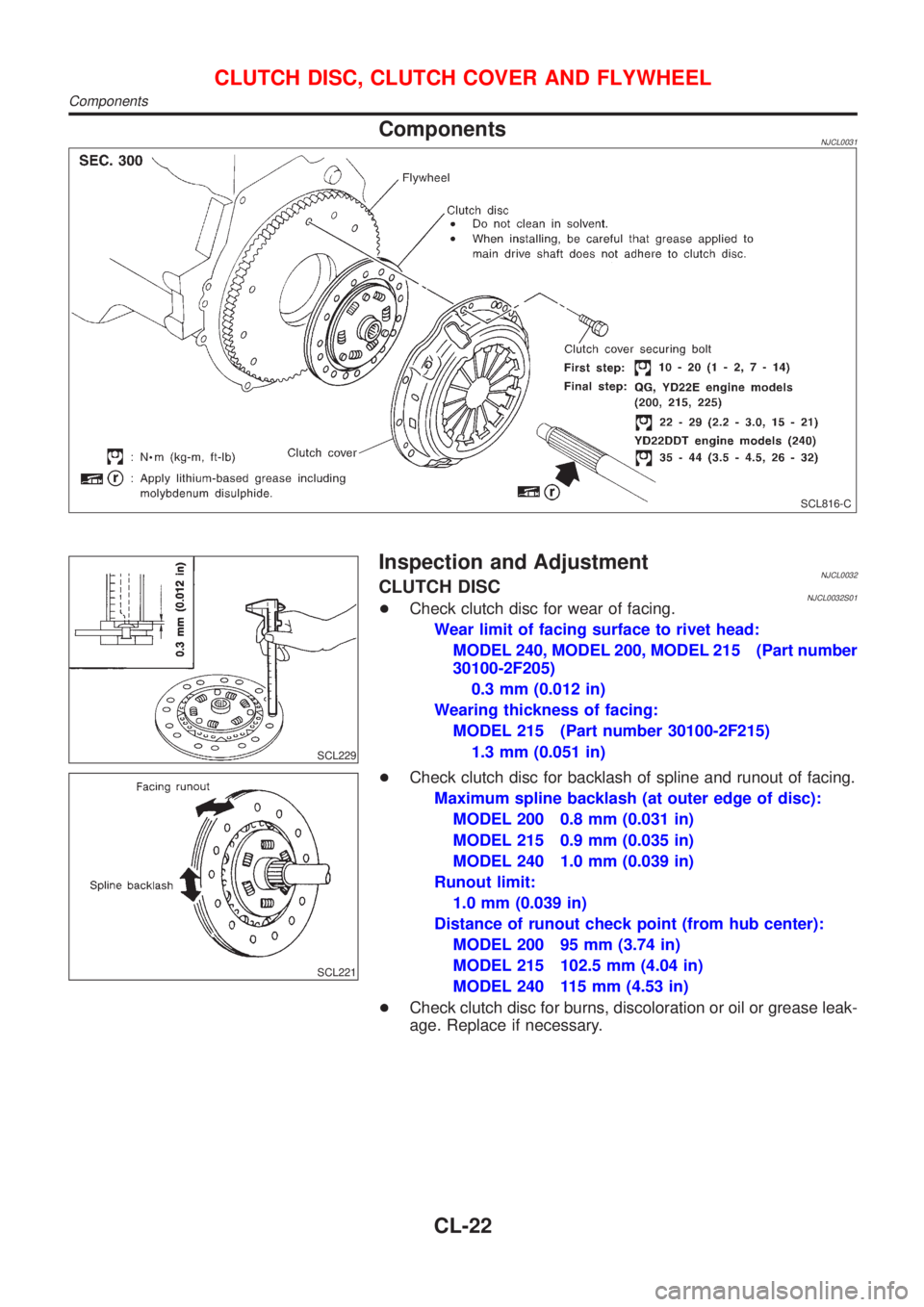
ComponentsNJCL0031
SCL816-C
SCL229
Inspection and AdjustmentNJCL0032CLUTCH DISCNJCL0032S01+Check clutch disc for wear of facing.
Wear limit of facing surface to rivet head:
MODEL 240, MODEL 200, MODEL 215 (Part number
30100-2F205)
0.3 mm (0.012 in)
Wearing thickness of facing:
MODEL 215 (Part number 30100-2F215)
1.3 mm (0.051 in)
SCL221
+Check clutch disc for backlash of spline and runout of facing.
Maximum spline backlash (at outer edge of disc):
MODEL 200 0.8 mm (0.031 in)
MODEL 215 0.9 mm (0.035 in)
MODEL 240 1.0 mm (0.039 in)
Runout limit:
1.0 mm (0.039 in)
Distance of runout check point (from hub center):
MODEL 200 95 mm (3.74 in)
MODEL 215 102.5 mm (4.04 in)
MODEL 240 115 mm (4.53 in)
+Check clutch disc for burns, discoloration or oil or grease leak-
age. Replace if necessary.
CLUTCH DISC, CLUTCH COVER AND FLYWHEEL
Components
CL-22
Page 723 of 2898
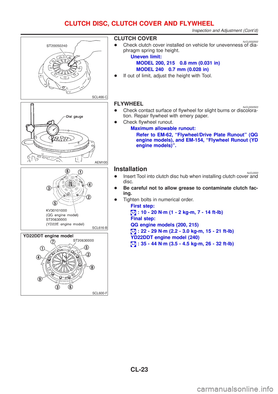
SCL466-C
CLUTCH COVERNJCL0032S02+Check clutch cover installed on vehicle for unevenness of dia-
phragm spring toe height.
Uneven limit:
MODEL 200, 215 0.8 mm (0.031 in)
MODEL 240 0.7 mm (0.028 in)
+If out of limit, adjust the height with Tool.
AEM100
FLYWHEELNJCL0032S03+Check contact surface of flywheel for slight burns or discolora-
tion. Repair flywheel with emery paper.
+Check flywheel runout.
Maximum allowable runout:
Refer to EM-62, ªFlywheel/Drive Plate Runoutº (QG
engine models), and EM-154, ªFlywheel Runout (YD
engine models)º.
SCL616-B
SCL600-F
InstallationNJCL0033+Insert Tool into clutch disc hub when installing clutch cover and
disc.
+Be careful not to allow grease to contaminate clutch fac-
ing.
+Tighten bolts in numerical order.
First step:
: 10 - 20 N´m (1 - 2 kg-m,7-14ft-lb)
Final step:
QG engine models (200, 215)
: 22 - 29 N´m (2.2 - 3.0 kg-m, 15 - 21 ft-lb)
YD22DDT engine model (240)
: 35 - 44 N´m (3.5 - 4.5 kg-m, 26 - 32 ft-lb)
CLUTCH DISC, CLUTCH COVER AND FLYWHEEL
Inspection and Adjustment (Cont'd)
CL-23
Page 724 of 2898
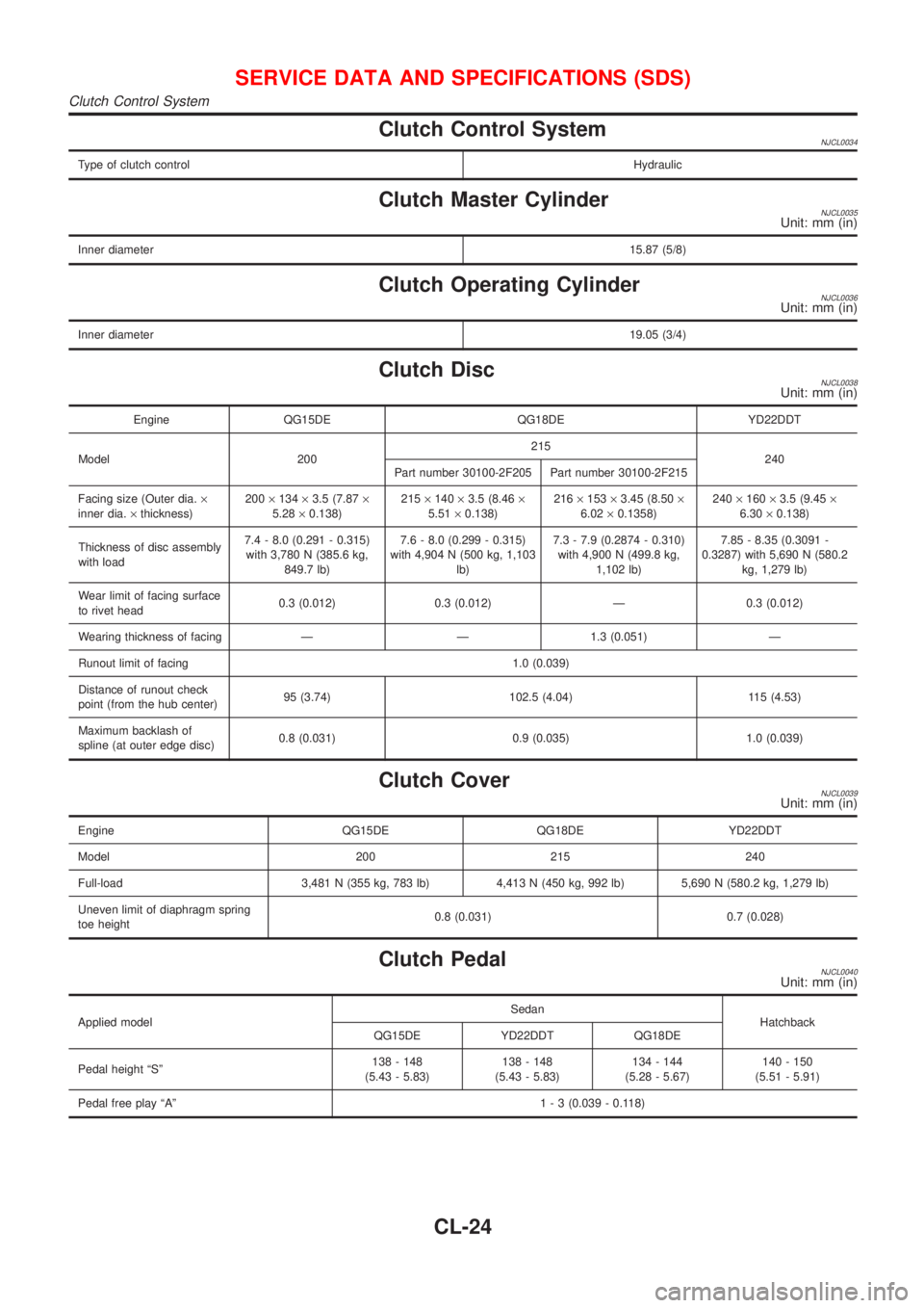
Clutch Control SystemNJCL0034
Type of clutch controlHydraulic
Clutch Master CylinderNJCL0035Unit: mm (in)
Inner diameter15.87 (5/8)
Clutch Operating CylinderNJCL0036Unit: mm (in)
Inner diameter19.05 (3/4)
Clutch DiscNJCL0038Unit: mm (in)
Engine QG15DE QG18DE YD22DDT
Model 200215
240
Part number 30100-2F205 Part number 30100-2F215
Facing size (Outer dia.´
inner dia.´thickness)200´134´3.5 (7.87´
5.28´0.138)215´140´3.5 (8.46´
5.51´0.138)216´153´3.45 (8.50´
6.02´0.1358)240´160´3.5 (9.45´
6.30´0.138)
Thickness of disc assembly
with load7.4 - 8.0 (0.291 - 0.315)
with 3,780 N (385.6 kg,
849.7 lb)7.6 - 8.0 (0.299 - 0.315)
with 4,904 N (500 kg, 1,103
lb)7.3 - 7.9 (0.2874 - 0.310)
with 4,900 N (499.8 kg,
1,102 lb)7.85 - 8.35 (0.3091 -
0.3287) with 5,690 N (580.2
kg, 1,279 lb)
Wear limit of facing surface
to rivet head0.3 (0.012) 0.3 (0.012) Ð 0.3 (0.012)
Wearing thickness of facing Ð Ð 1.3 (0.051) Ð
Runout limit of facing 1.0 (0.039)
Distance of runout check
point (from the hub center)95 (3.74) 102.5 (4.04) 115 (4.53)
Maximum backlash of
spline (at outer edge disc)0.8 (0.031) 0.9 (0.035) 1.0 (0.039)
Clutch CoverNJCL0039Unit: mm (in)
Engine QG15DE QG18DE YD22DDT
Model 200 215 240
Full-load 3,481 N (355 kg, 783 lb) 4,413 N (450 kg, 992 lb) 5,690 N (580.2 kg, 1,279 lb)
Uneven limit of diaphragm spring
toe height0.8 (0.031) 0.7 (0.028)
Clutch PedalNJCL0040Unit: mm (in)
Applied modelSedan
Hatchback
QG15DE YD22DDT QG18DE
Pedal height ªSº138 - 148
(5.43 - 5.83)138 - 148
(5.43 - 5.83)134 - 144
(5.28 - 5.67)140 - 150
(5.51 - 5.91)
Pedal free play ªAº1 - 3 (0.039 - 0.118)
SERVICE DATA AND SPECIFICATIONS (SDS)
Clutch Control System
CL-24
Page 725 of 2898
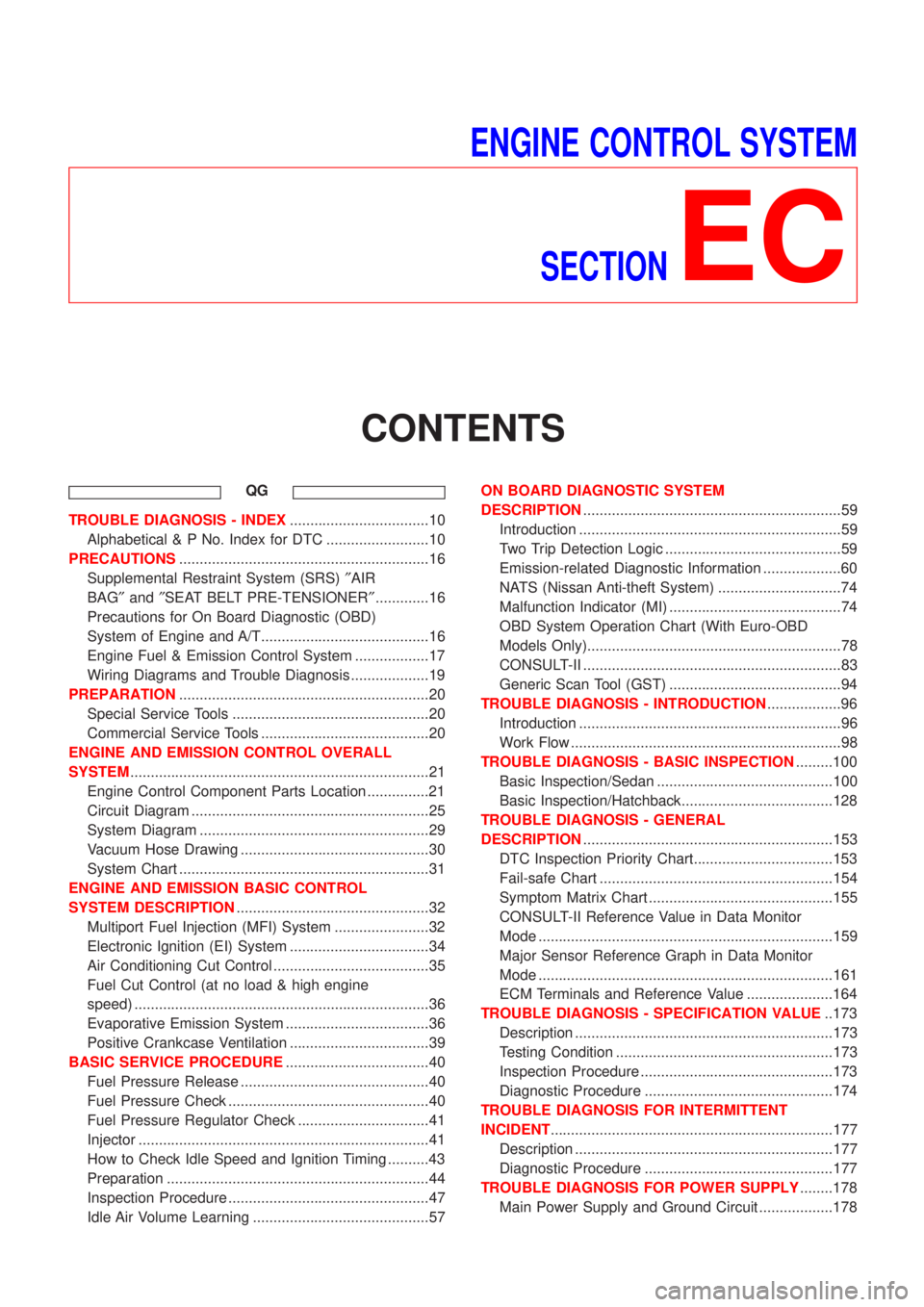
ENGINE CONTROL SYSTEM
SECTION
EC
CONTENTS
QG
TROUBLE DIAGNOSIS - INDEX..................................10
Alphabetical & P No. Index for DTC .........................10
PRECAUTIONS.............................................................16
Supplemental Restraint System (SRS)²AIR
BAG²and²SEAT BELT PRE-TENSIONER².............16
Precautions for On Board Diagnostic (OBD)
System of Engine and A/T.........................................16
Engine Fuel & Emission Control System ..................17
Wiring Diagrams and Trouble Diagnosis ...................19
PREPARATION.............................................................20
Special Service Tools ................................................20
Commercial Service Tools .........................................20
ENGINE AND EMISSION CONTROL OVERALL
SYSTEM.........................................................................21
Engine Control Component Parts Location ...............21
Circuit Diagram ..........................................................25
System Diagram ........................................................29
Vacuum Hose Drawing ..............................................30
System Chart .............................................................31
ENGINE AND EMISSION BASIC CONTROL
SYSTEM DESCRIPTION...............................................32
Multiport Fuel Injection (MFI) System .......................32
Electronic Ignition (EI) System ..................................34
Air Conditioning Cut Control ......................................35
Fuel Cut Control (at no load & high engine
speed) ........................................................................36
Evaporative Emission System ...................................36
Positive Crankcase Ventilation ..................................39
BASIC SERVICE PROCEDURE...................................40
Fuel Pressure Release ..............................................40
Fuel Pressure Check .................................................40
Fuel Pressure Regulator Check ................................41
Injector .......................................................................41
How to Check Idle Speed and Ignition Timing ..........43
Preparation ................................................................44
Inspection Procedure .................................................47
Idle Air Volume Learning ...........................................57ON BOARD DIAGNOSTIC SYSTEM
DESCRIPTION...............................................................59
Introduction ................................................................59
Two Trip Detection Logic ...........................................59
Emission-related Diagnostic Information ...................60
NATS (Nissan Anti-theft System) ..............................74
Malfunction Indicator (MI) ..........................................74
OBD System Operation Chart (With Euro-OBD
Models Only)..............................................................78
CONSULT-II ...............................................................83
Generic Scan Tool (GST) ..........................................94
TROUBLE DIAGNOSIS - INTRODUCTION..................96
Introduction ................................................................96
Work Flow ..................................................................98
TROUBLE DIAGNOSIS - BASIC INSPECTION.........100
Basic Inspection/Sedan ...........................................100
Basic Inspection/Hatchback.....................................128
TROUBLE DIAGNOSIS - GENERAL
DESCRIPTION.............................................................153
DTC Inspection Priority Chart..................................153
Fail-safe Chart .........................................................154
Symptom Matrix Chart .............................................155
CONSULT-II Reference Value in Data Monitor
Mode ........................................................................159
Major Sensor Reference Graph in Data Monitor
Mode ........................................................................161
ECM Terminals and Reference Value .....................164
TROUBLE DIAGNOSIS - SPECIFICATION VALUE..173
Description ...............................................................173
Testing Condition .....................................................173
Inspection Procedure ...............................................173
Diagnostic Procedure ..............................................174
TROUBLE DIAGNOSIS FOR INTERMITTENT
INCIDENT.....................................................................177
Description ...............................................................177
Diagnostic Procedure ..............................................177
TROUBLE DIAGNOSIS FOR POWER SUPPLY........178
Main Power Supply and Ground Circuit ..................178
Page 726 of 2898
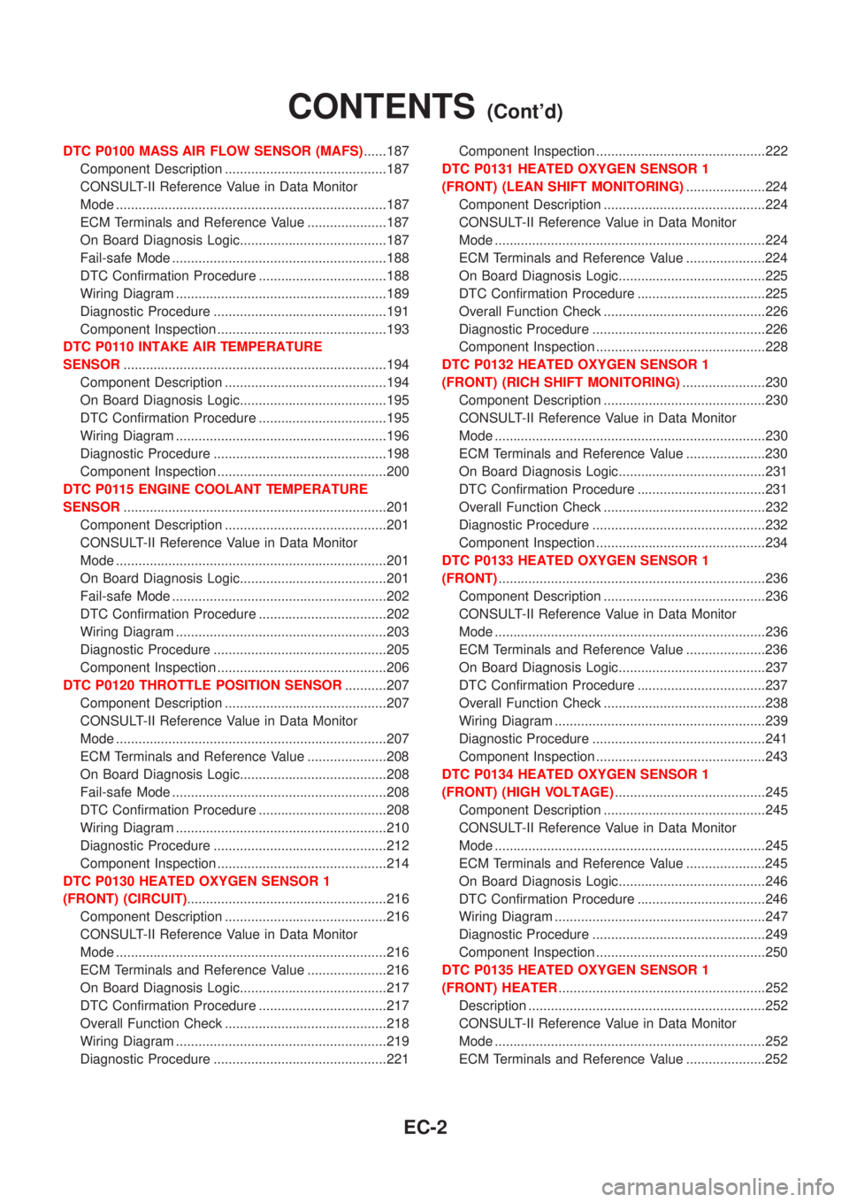
DTC P0100 MASS AIR FLOW SENSOR (MAFS)......187
Component Description ...........................................187
CONSULT-II Reference Value in Data Monitor
Mode ........................................................................187
ECM Terminals and Reference Value .....................187
On Board Diagnosis Logic.......................................187
Fail-safe Mode .........................................................188
DTC Confirmation Procedure ..................................188
Wiring Diagram ........................................................189
Diagnostic Procedure ..............................................191
Component Inspection .............................................193
DTC P0110 INTAKE AIR TEMPERATURE
SENSOR......................................................................194
Component Description ...........................................194
On Board Diagnosis Logic.......................................195
DTC Confirmation Procedure ..................................195
Wiring Diagram ........................................................196
Diagnostic Procedure ..............................................198
Component Inspection .............................................200
DTC P0115 ENGINE COOLANT TEMPERATURE
SENSOR......................................................................201
Component Description ...........................................201
CONSULT-II Reference Value in Data Monitor
Mode ........................................................................201
On Board Diagnosis Logic.......................................201
Fail-safe Mode .........................................................202
DTC Confirmation Procedure ..................................202
Wiring Diagram ........................................................203
Diagnostic Procedure ..............................................205
Component Inspection .............................................206
DTC P0120 THROTTLE POSITION SENSOR...........207
Component Description ...........................................207
CONSULT-II Reference Value in Data Monitor
Mode ........................................................................207
ECM Terminals and Reference Value .....................208
On Board Diagnosis Logic.......................................208
Fail-safe Mode .........................................................208
DTC Confirmation Procedure ..................................208
Wiring Diagram ........................................................210
Diagnostic Procedure ..............................................212
Component Inspection .............................................214
DTC P0130 HEATED OXYGEN SENSOR 1
(FRONT) (CIRCUIT).....................................................216
Component Description ...........................................216
CONSULT-II Reference Value in Data Monitor
Mode ........................................................................216
ECM Terminals and Reference Value .....................216
On Board Diagnosis Logic.......................................217
DTC Confirmation Procedure ..................................217
Overall Function Check ...........................................218
Wiring Diagram ........................................................219
Diagnostic Procedure ..............................................221Component Inspection .............................................222
DTC P0131 HEATED OXYGEN SENSOR 1
(FRONT) (LEAN SHIFT MONITORING).....................224
Component Description ...........................................224
CONSULT-II Reference Value in Data Monitor
Mode ........................................................................224
ECM Terminals and Reference Value .....................224
On Board Diagnosis Logic.......................................225
DTC Confirmation Procedure ..................................225
Overall Function Check ...........................................226
Diagnostic Procedure ..............................................226
Component Inspection .............................................228
DTC P0132 HEATED OXYGEN SENSOR 1
(FRONT) (RICH SHIFT MONITORING)......................230
Component Description ...........................................230
CONSULT-II Reference Value in Data Monitor
Mode ........................................................................230
ECM Terminals and Reference Value .....................230
On Board Diagnosis Logic.......................................231
DTC Confirmation Procedure ..................................231
Overall Function Check ...........................................232
Diagnostic Procedure ..............................................232
Component Inspection .............................................234
DTC P0133 HEATED OXYGEN SENSOR 1
(FRONT).......................................................................236
Component Description ...........................................236
CONSULT-II Reference Value in Data Monitor
Mode ........................................................................236
ECM Terminals and Reference Value .....................236
On Board Diagnosis Logic.......................................237
DTC Confirmation Procedure ..................................237
Overall Function Check ...........................................238
Wiring Diagram ........................................................239
Diagnostic Procedure ..............................................241
Component Inspection .............................................243
DTC P0134 HEATED OXYGEN SENSOR 1
(FRONT) (HIGH VOLTAGE)........................................245
Component Description ...........................................245
CONSULT-II Reference Value in Data Monitor
Mode ........................................................................245
ECM Terminals and Reference Value .....................245
On Board Diagnosis Logic.......................................246
DTC Confirmation Procedure ..................................246
Wiring Diagram ........................................................247
Diagnostic Procedure ..............................................249
Component Inspection .............................................250
DTC P0135 HEATED OXYGEN SENSOR 1
(FRONT) HEATER.......................................................252
Description ...............................................................252
CONSULT-II Reference Value in Data Monitor
Mode ........................................................................252
ECM Terminals and Reference Value .....................252
CONTENTS(Cont'd)
EC-2
Page 727 of 2898
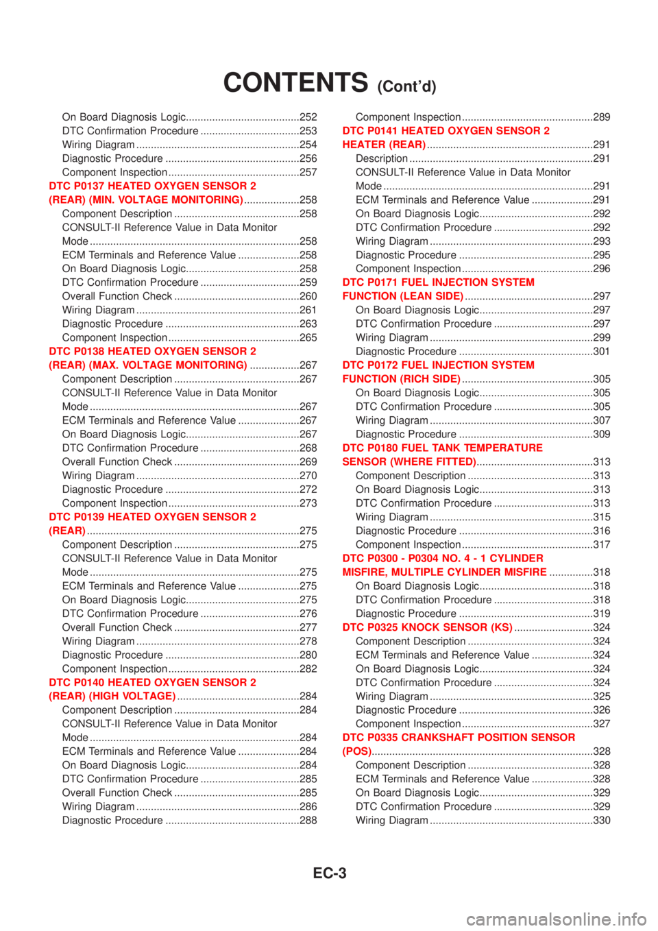
On Board Diagnosis Logic.......................................252
DTC Confirmation Procedure ..................................253
Wiring Diagram ........................................................254
Diagnostic Procedure ..............................................256
Component Inspection .............................................257
DTC P0137 HEATED OXYGEN SENSOR 2
(REAR) (MIN. VOLTAGE MONITORING)...................258
Component Description ...........................................258
CONSULT-II Reference Value in Data Monitor
Mode ........................................................................258
ECM Terminals and Reference Value .....................258
On Board Diagnosis Logic.......................................258
DTC Confirmation Procedure ..................................259
Overall Function Check ...........................................260
Wiring Diagram ........................................................261
Diagnostic Procedure ..............................................263
Component Inspection .............................................265
DTC P0138 HEATED OXYGEN SENSOR 2
(REAR) (MAX. VOLTAGE MONITORING).................267
Component Description ...........................................267
CONSULT-II Reference Value in Data Monitor
Mode ........................................................................267
ECM Terminals and Reference Value .....................267
On Board Diagnosis Logic.......................................267
DTC Confirmation Procedure ..................................268
Overall Function Check ...........................................269
Wiring Diagram ........................................................270
Diagnostic Procedure ..............................................272
Component Inspection .............................................273
DTC P0139 HEATED OXYGEN SENSOR 2
(REAR).........................................................................275
Component Description ...........................................275
CONSULT-II Reference Value in Data Monitor
Mode ........................................................................275
ECM Terminals and Reference Value .....................275
On Board Diagnosis Logic.......................................275
DTC Confirmation Procedure ..................................276
Overall Function Check ...........................................277
Wiring Diagram ........................................................278
Diagnostic Procedure ..............................................280
Component Inspection .............................................282
DTC P0140 HEATED OXYGEN SENSOR 2
(REAR) (HIGH VOLTAGE)..........................................284
Component Description ...........................................284
CONSULT-II Reference Value in Data Monitor
Mode ........................................................................284
ECM Terminals and Reference Value .....................284
On Board Diagnosis Logic.......................................284
DTC Confirmation Procedure ..................................285
Overall Function Check ...........................................285
Wiring Diagram ........................................................286
Diagnostic Procedure ..............................................288Component Inspection .............................................289
DTC P0141 HEATED OXYGEN SENSOR 2
HEATER (REAR).........................................................291
Description ...............................................................291
CONSULT-II Reference Value in Data Monitor
Mode ........................................................................291
ECM Terminals and Reference Value .....................291
On Board Diagnosis Logic.......................................292
DTC Confirmation Procedure ..................................292
Wiring Diagram ........................................................293
Diagnostic Procedure ..............................................295
Component Inspection .............................................296
DTC P0171 FUEL INJECTION SYSTEM
FUNCTION (LEAN SIDE)............................................297
On Board Diagnosis Logic.......................................297
DTC Confirmation Procedure ..................................297
Wiring Diagram ........................................................299
Diagnostic Procedure ..............................................301
DTC P0172 FUEL INJECTION SYSTEM
FUNCTION (RICH SIDE).............................................305
On Board Diagnosis Logic.......................................305
DTC Confirmation Procedure ..................................305
Wiring Diagram ........................................................307
Diagnostic Procedure ..............................................309
DTC P0180 FUEL TANK TEMPERATURE
SENSOR (WHERE FITTED)........................................313
Component Description ...........................................313
On Board Diagnosis Logic.......................................313
DTC Confirmation Procedure ..................................313
Wiring Diagram ........................................................315
Diagnostic Procedure ..............................................316
Component Inspection .............................................317
DTC P0300 - P0304 NO.4-1CYLINDER
MISFIRE, MULTIPLE CYLINDER MISFIRE...............318
On Board Diagnosis Logic.......................................318
DTC Confirmation Procedure ..................................318
Diagnostic Procedure ..............................................319
DTC P0325 KNOCK SENSOR (KS)...........................324
Component Description ...........................................324
ECM Terminals and Reference Value .....................324
On Board Diagnosis Logic.......................................324
DTC Confirmation Procedure ..................................324
Wiring Diagram ........................................................325
Diagnostic Procedure ..............................................326
Component Inspection .............................................327
DTC P0335 CRANKSHAFT POSITION SENSOR
(POS)............................................................................328
Component Description ...........................................328
ECM Terminals and Reference Value .....................328
On Board Diagnosis Logic.......................................329
DTC Confirmation Procedure ..................................329
Wiring Diagram ........................................................330
CONTENTS(Cont'd)
EC-3
Page 728 of 2898
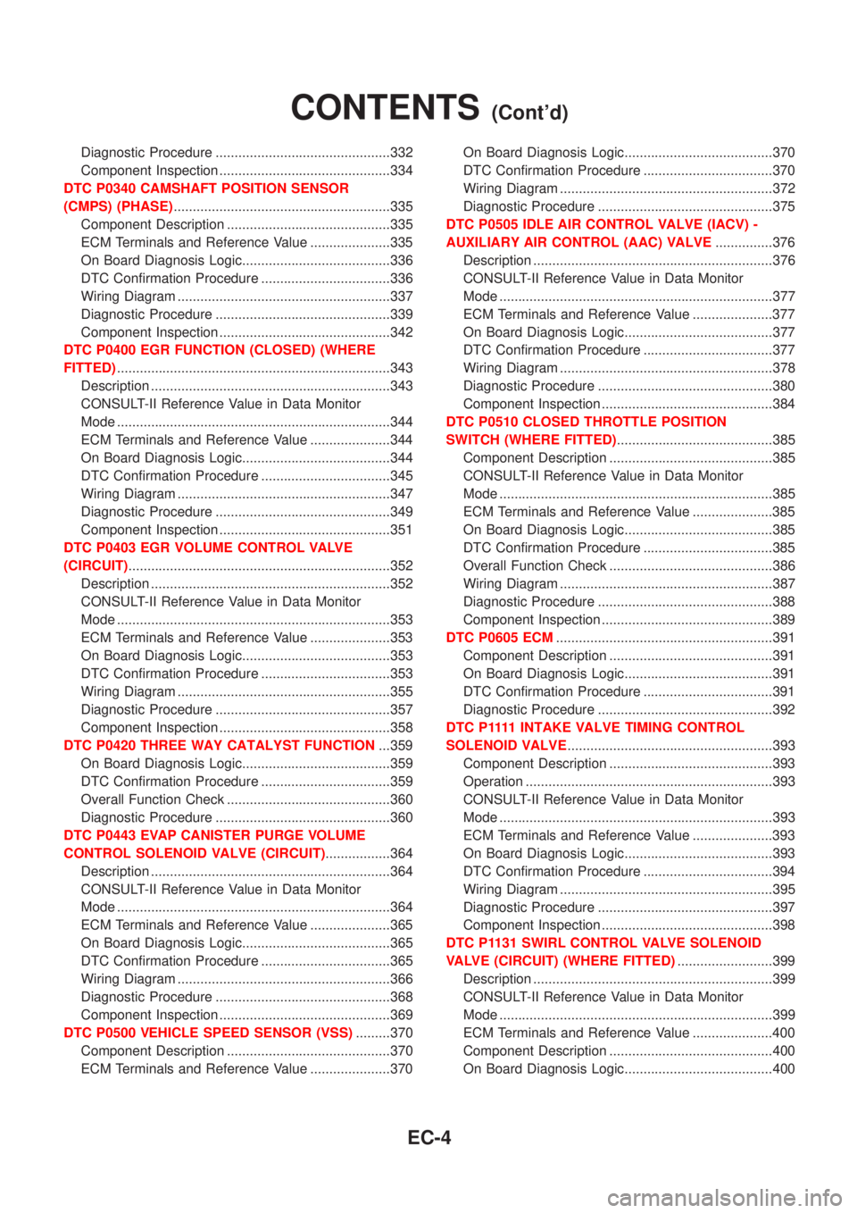
Diagnostic Procedure ..............................................332
Component Inspection .............................................334
DTC P0340 CAMSHAFT POSITION SENSOR
(CMPS) (PHASE).........................................................335
Component Description ...........................................335
ECM Terminals and Reference Value .....................335
On Board Diagnosis Logic.......................................336
DTC Confirmation Procedure ..................................336
Wiring Diagram ........................................................337
Diagnostic Procedure ..............................................339
Component Inspection .............................................342
DTC P0400 EGR FUNCTION (CLOSED) (WHERE
FITTED)........................................................................343
Description ...............................................................343
CONSULT-II Reference Value in Data Monitor
Mode ........................................................................344
ECM Terminals and Reference Value .....................344
On Board Diagnosis Logic.......................................344
DTC Confirmation Procedure ..................................345
Wiring Diagram ........................................................347
Diagnostic Procedure ..............................................349
Component Inspection .............................................351
DTC P0403 EGR VOLUME CONTROL VALVE
(CIRCUIT).....................................................................352
Description ...............................................................352
CONSULT-II Reference Value in Data Monitor
Mode ........................................................................353
ECM Terminals and Reference Value .....................353
On Board Diagnosis Logic.......................................353
DTC Confirmation Procedure ..................................353
Wiring Diagram ........................................................355
Diagnostic Procedure ..............................................357
Component Inspection .............................................358
DTC P0420 THREE WAY CATALYST FUNCTION...359
On Board Diagnosis Logic.......................................359
DTC Confirmation Procedure ..................................359
Overall Function Check ...........................................360
Diagnostic Procedure ..............................................360
DTC P0443 EVAP CANISTER PURGE VOLUME
CONTROL SOLENOID VALVE (CIRCUIT).................364
Description ...............................................................364
CONSULT-II Reference Value in Data Monitor
Mode ........................................................................364
ECM Terminals and Reference Value .....................365
On Board Diagnosis Logic.......................................365
DTC Confirmation Procedure ..................................365
Wiring Diagram ........................................................366
Diagnostic Procedure ..............................................368
Component Inspection .............................................369
DTC P0500 VEHICLE SPEED SENSOR (VSS).........370
Component Description ...........................................370
ECM Terminals and Reference Value .....................370On Board Diagnosis Logic.......................................370
DTC Confirmation Procedure ..................................370
Wiring Diagram ........................................................372
Diagnostic Procedure ..............................................375
DTC P0505 IDLE AIR CONTROL VALVE (IACV) -
AUXILIARY AIR CONTROL (AAC) VALVE...............376
Description ...............................................................376
CONSULT-II Reference Value in Data Monitor
Mode ........................................................................377
ECM Terminals and Reference Value .....................377
On Board Diagnosis Logic.......................................377
DTC Confirmation Procedure ..................................377
Wiring Diagram ........................................................378
Diagnostic Procedure ..............................................380
Component Inspection .............................................384
DTC P0510 CLOSED THROTTLE POSITION
SWITCH (WHERE FITTED).........................................385
Component Description ...........................................385
CONSULT-II Reference Value in Data Monitor
Mode ........................................................................385
ECM Terminals and Reference Value .....................385
On Board Diagnosis Logic.......................................385
DTC Confirmation Procedure ..................................385
Overall Function Check ...........................................386
Wiring Diagram ........................................................387
Diagnostic Procedure ..............................................388
Component Inspection .............................................389
DTC P0605 ECM.........................................................391
Component Description ...........................................391
On Board Diagnosis Logic.......................................391
DTC Confirmation Procedure ..................................391
Diagnostic Procedure ..............................................392
D T C P 1111INTAKE VALVE TIMING CONTROL
SOLENOID VALVE......................................................393
Component Description ...........................................393
Operation .................................................................393
CONSULT-II Reference Value in Data Monitor
Mode ........................................................................393
ECM Terminals and Reference Value .....................393
On Board Diagnosis Logic.......................................393
DTC Confirmation Procedure ..................................394
Wiring Diagram ........................................................395
Diagnostic Procedure ..............................................397
Component Inspection .............................................398
DTC P1131 SWIRL CONTROL VALVE SOLENOID
VALVE (CIRCUIT) (WHERE FITTED).........................399
Description ...............................................................399
CONSULT-II Reference Value in Data Monitor
Mode ........................................................................399
ECM Terminals and Reference Value .....................400
Component Description ...........................................400
On Board Diagnosis Logic.......................................400
CONTENTS(Cont'd)
EC-4
Page 729 of 2898
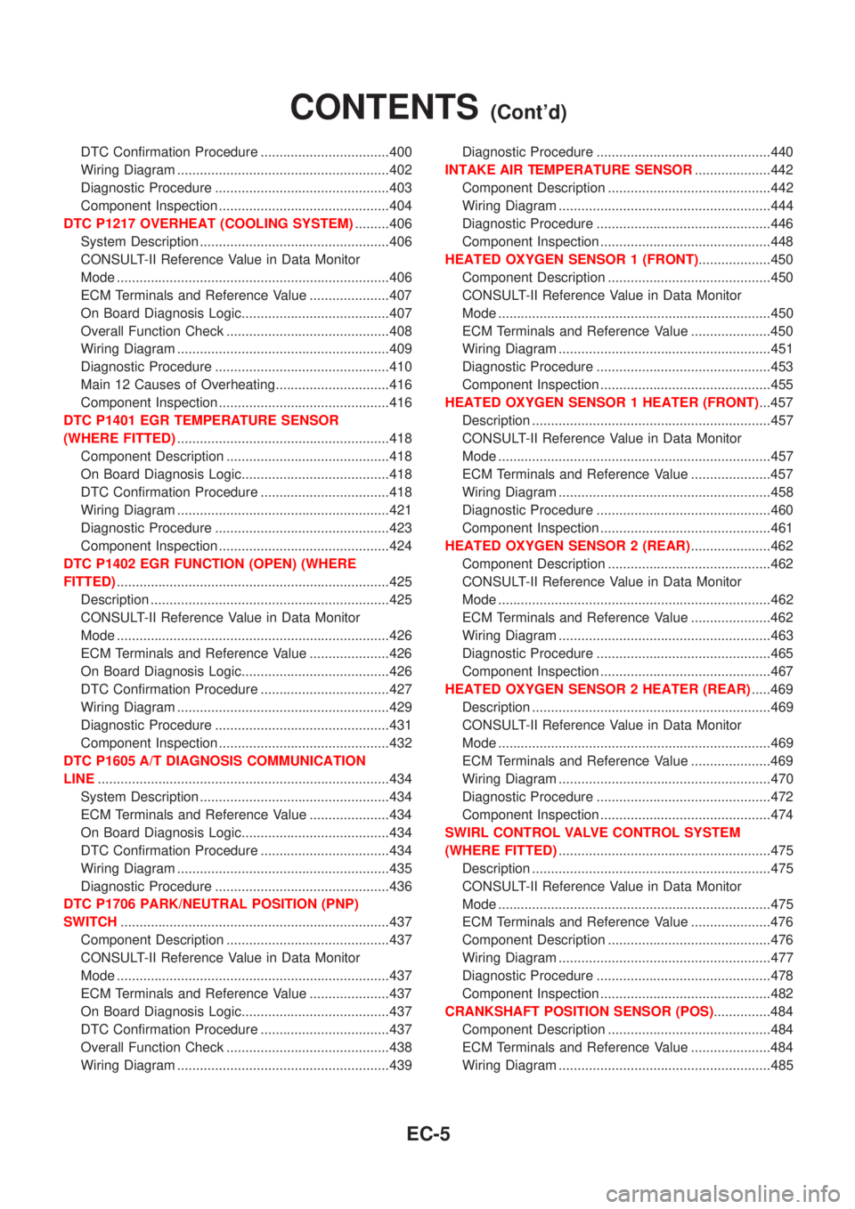
DTC Confirmation Procedure ..................................400
Wiring Diagram ........................................................402
Diagnostic Procedure ..............................................403
Component Inspection .............................................404
DTC P1217 OVERHEAT (COOLING SYSTEM).........406
System Description ..................................................406
CONSULT-II Reference Value in Data Monitor
Mode ........................................................................406
ECM Terminals and Reference Value .....................407
On Board Diagnosis Logic.......................................407
Overall Function Check ...........................................408
Wiring Diagram ........................................................409
Diagnostic Procedure ..............................................410
Main 12 Causes of Overheating..............................416
Component Inspection .............................................416
DTC P1401 EGR TEMPERATURE SENSOR
(WHERE FITTED)........................................................418
Component Description ...........................................418
On Board Diagnosis Logic.......................................418
DTC Confirmation Procedure ..................................418
Wiring Diagram ........................................................421
Diagnostic Procedure ..............................................423
Component Inspection .............................................424
DTC P1402 EGR FUNCTION (OPEN) (WHERE
FITTED)........................................................................425
Description ...............................................................425
CONSULT-II Reference Value in Data Monitor
Mode ........................................................................426
ECM Terminals and Reference Value .....................426
On Board Diagnosis Logic.......................................426
DTC Confirmation Procedure ..................................427
Wiring Diagram ........................................................429
Diagnostic Procedure ..............................................431
Component Inspection .............................................432
DTC P1605 A/T DIAGNOSIS COMMUNICATION
LINE.............................................................................434
System Description ..................................................434
ECM Terminals and Reference Value .....................434
On Board Diagnosis Logic.......................................434
DTC Confirmation Procedure ..................................434
Wiring Diagram ........................................................435
Diagnostic Procedure ..............................................436
DTC P1706 PARK/NEUTRAL POSITION (PNP)
SWITCH.......................................................................437
Component Description ...........................................437
CONSULT-II Reference Value in Data Monitor
Mode ........................................................................437
ECM Terminals and Reference Value .....................437
On Board Diagnosis Logic.......................................437
DTC Confirmation Procedure ..................................437
Overall Function Check ...........................................438
Wiring Diagram ........................................................439Diagnostic Procedure ..............................................440
INTAKE AIR TEMPERATURE SENSOR....................442
Component Description ...........................................442
Wiring Diagram ........................................................444
Diagnostic Procedure ..............................................446
Component Inspection .............................................448
HEATED OXYGEN SENSOR 1 (FRONT)...................450
Component Description ...........................................450
CONSULT-II Reference Value in Data Monitor
Mode ........................................................................450
ECM Terminals and Reference Value .....................450
Wiring Diagram ........................................................451
Diagnostic Procedure ..............................................453
Component Inspection .............................................455
HEATED OXYGEN SENSOR 1 HEATER (FRONT)...457
Description ...............................................................457
CONSULT-II Reference Value in Data Monitor
Mode ........................................................................457
ECM Terminals and Reference Value .....................457
Wiring Diagram ........................................................458
Diagnostic Procedure ..............................................460
Component Inspection .............................................461
HEATED OXYGEN SENSOR 2 (REAR).....................462
Component Description ...........................................462
CONSULT-II Reference Value in Data Monitor
Mode ........................................................................462
ECM Terminals and Reference Value .....................462
Wiring Diagram ........................................................463
Diagnostic Procedure ..............................................465
Component Inspection .............................................467
HEATED OXYGEN SENSOR 2 HEATER (REAR).....469
Description ...............................................................469
CONSULT-II Reference Value in Data Monitor
Mode ........................................................................469
ECM Terminals and Reference Value .....................469
Wiring Diagram ........................................................470
Diagnostic Procedure ..............................................472
Component Inspection .............................................474
SWIRL CONTROL VALVE CONTROL SYSTEM
(WHERE FITTED)........................................................475
Description ...............................................................475
CONSULT-II Reference Value in Data Monitor
Mode ........................................................................475
ECM Terminals and Reference Value .....................476
Component Description ...........................................476
Wiring Diagram ........................................................477
Diagnostic Procedure ..............................................478
Component Inspection .............................................482
CRANKSHAFT POSITION SENSOR (POS)...............484
Component Description ...........................................484
ECM Terminals and Reference Value .....................484
Wiring Diagram ........................................................485
CONTENTS(Cont'd)
EC-5
Page 730 of 2898
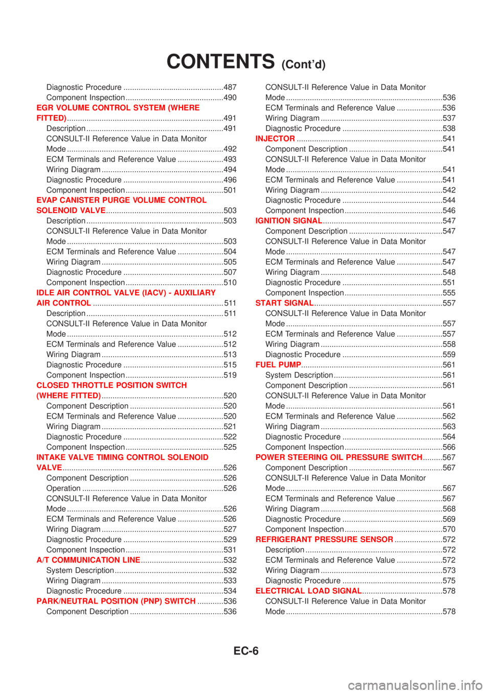
Diagnostic Procedure ..............................................487
Component Inspection .............................................490
EGR VOLUME CONTROL SYSTEM (WHERE
FITTED)........................................................................491
Description ...............................................................491
CONSULT-II Reference Value in Data Monitor
Mode ........................................................................492
ECM Terminals and Reference Value .....................493
Wiring Diagram ........................................................494
Diagnostic Procedure ..............................................496
Component Inspection .............................................501
EVAP CANISTER PURGE VOLUME CONTROL
SOLENOID VALVE......................................................503
Description ...............................................................503
CONSULT-II Reference Value in Data Monitor
Mode ........................................................................503
ECM Terminals and Reference Value .....................504
Wiring Diagram ........................................................505
Diagnostic Procedure ..............................................507
Component Inspection .............................................510
IDLE AIR CONTROL VALVE (IACV) - AUXILIARY
AIR CONTROL............................................................ 511
Description ............................................................... 511
CONSULT-II Reference Value in Data Monitor
Mode ........................................................................512
ECM Terminals and Reference Value .....................512
Wiring Diagram ........................................................513
Diagnostic Procedure ..............................................515
Component Inspection .............................................519
CLOSED THROTTLE POSITION SWITCH
(WHERE FITTED)........................................................520
Component Description ...........................................520
ECM Terminals and Reference Value .....................520
Wiring Diagram ........................................................521
Diagnostic Procedure ..............................................522
Component Inspection .............................................525
INTAKE VALVE TIMING CONTROL SOLENOID
VALVE..........................................................................526
Component Description ...........................................526
Operation .................................................................526
CONSULT-II Reference Value in Data Monitor
Mode ........................................................................526
ECM Terminals and Reference Value .....................526
Wiring Diagram ........................................................527
Diagnostic Procedure ..............................................529
Component Inspection .............................................531
A/T COMMUNICATION LINE......................................532
System Description ..................................................532
Wiring Diagram ........................................................533
Diagnostic Procedure ..............................................534
PARK/NEUTRAL POSITION (PNP) SWITCH............536
Component Description ...........................................536CONSULT-II Reference Value in Data Monitor
Mode ........................................................................536
ECM Terminals and Reference Value .....................536
Wiring Diagram ........................................................537
Diagnostic Procedure ..............................................538
INJECTOR...................................................................541
Component Description ...........................................541
CONSULT-II Reference Value in Data Monitor
Mode ........................................................................541
ECM Terminals and Reference Value .....................541
Wiring Diagram ........................................................542
Diagnostic Procedure ..............................................544
Component Inspection .............................................546
IGNITION SIGNAL.......................................................547
Component Description ...........................................547
CONSULT-II Reference Value in Data Monitor
Mode ........................................................................547
ECM Terminals and Reference Value .....................547
Wiring Diagram ........................................................548
Diagnostic Procedure ..............................................551
Component Inspection .............................................555
START SIGNAL...........................................................557
CONSULT-II Reference Value in Data Monitor
Mode ........................................................................557
ECM Terminals and Reference Value .....................557
Wiring Diagram ........................................................558
Diagnostic Procedure ..............................................559
FUEL PUMP.................................................................561
System Description ..................................................561
Component Description ...........................................561
CONSULT-II Reference Value in Data Monitor
Mode ........................................................................561
ECM Terminals and Reference Value .....................562
Wiring Diagram ........................................................563
Diagnostic Procedure ..............................................564
Component Inspection .............................................566
POWER STEERING OIL PRESSURE SWITCH.........567
Component Description ...........................................567
CONSULT-II Reference Value in Data Monitor
Mode ........................................................................567
ECM Terminals and Reference Value .....................567
Wiring Diagram ........................................................568
Diagnostic Procedure ..............................................569
Component Inspection .............................................570
REFRIGERANT PRESSURE SENSOR......................572
Description ...............................................................572
ECM Terminals and Reference Value .....................572
Wiring Diagram ........................................................573
Diagnostic Procedure ..............................................575
ELECTRICAL LOAD SIGNAL.....................................578
CONSULT-II Reference Value in Data Monitor
Mode ........................................................................578
CONTENTS(Cont'd)
EC-6