NISSAN ALMERA N15 1995 Service Manual
Manufacturer: NISSAN, Model Year: 1995, Model line: ALMERA N15, Model: NISSAN ALMERA N15 1995Pages: 1701, PDF Size: 82.27 MB
Page 1481 of 1701
Pulleyassembly SERVICE
PROCEDURES
Compressor Clutch(Cont'd)
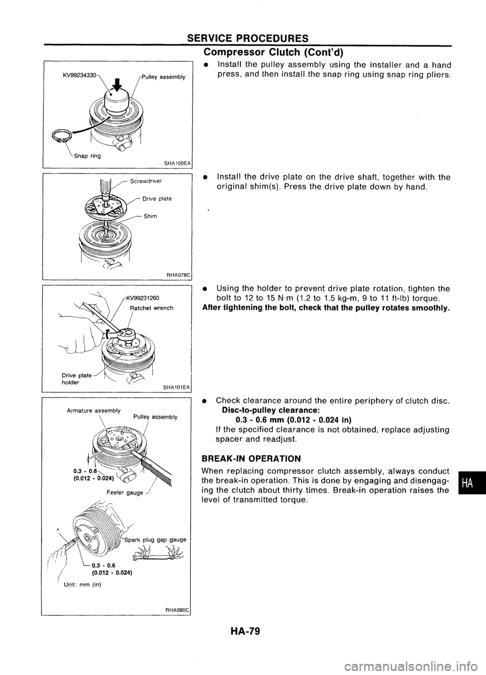
• Install thepulley assembly usingtheinstaller andahand
press, andthen install thesnap ringusing snapring
pliers.
SHA100EA
•Install thedrive plateonthe drive shaft, together withthe
original shim(s). Pressthedrive platedown byhand.
Drive plate
-Shim
RHA07BC
•Using theholder toprevent driveplaterotation, tightenthe
bolt to12to15 N'm (1.2to1.5 kg-m, 9to 11ft-Ib) torque.
After tightening thebolt, check thatthepulley rotates smoothly.
• Check clearance aroundtheentire periphery ofclutch disc.
Disc-to-pulley clearance:
0.3 -0.6 mm (0.012 -0.024 in)
If the specified clearance isnot obtained, replaceadjusting
spacer andreadjust.
BREAK-IN OPERATION
When replacing compressor clutchassembly, alwaysconduct •
the break-in operation. Thisisdone byengaging anddisengag-
i
ing the clutch aboutthirtytimes. Break-in operation raisesthe
level oftransmitted torque.
SHA101EA
Pulley assembly
/
Feeler gauge
-.I
-~~ 'Sparkpluggapgauge
~
Drive
plate
holder
(
Unit:mm(in)
RHAOBOCHA-79
Page 1482 of 1701
SERVICEPROCEDURES
Thermal Protector
INSPECTION
• When servicing, donot allow foreign mattertoget into com-
pressor.
• Check continuity betweentwoterminals.
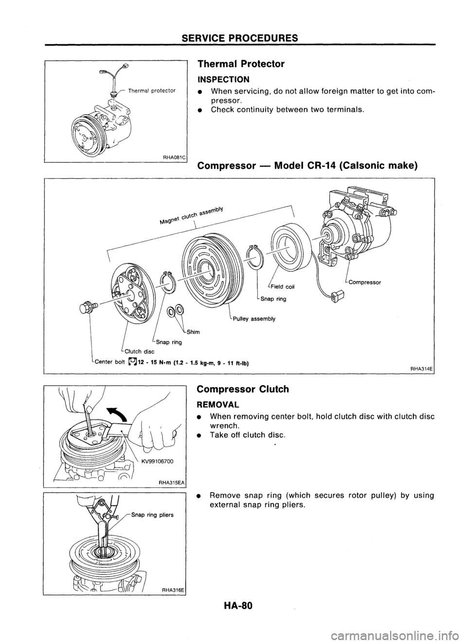
Compressor -Model CR-14(Calsonic make)
Pulley assembly
Snap ring
Clutch disc
Center bolt~12 -
15 N.m
(1.2-1.5 kg-m, 9-
11 ft-Ib)
RHA314E
Compressor Clutch
REMOVAL
• When removing centerbolt,holdclutch discwithclutch disc
wrench.
• Take offclutch disc.
• Remove snapring(which secures rotorpulley) byusing
external snapringpliers.
HA-80
Page 1483 of 1701
RHA317ESERVICE
PROCEDURES
Compressor Clutch(Cont'd)
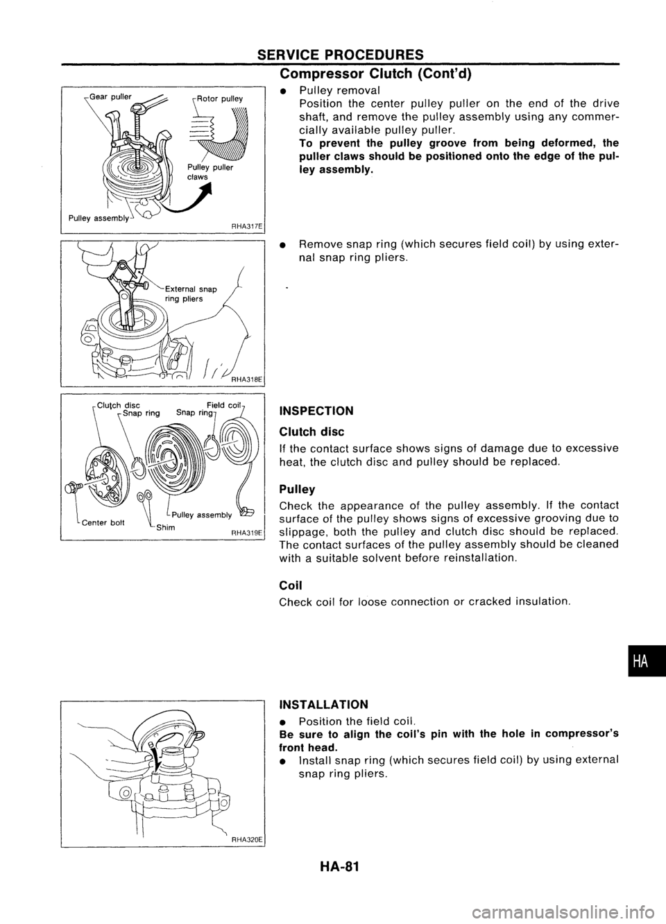
• Pulley removal
Position thecenter pulleypulleronthe end ofthe drive
shaft, andremove thepulley assembly usinganycommer-
cially available pulleypuller.
To prevent thepulley groove frombeing deformed, the
puller clawsshould bepositioned ontotheedge ofthe pul-
ley assembly.
~~
\t
PUlleyassembly
-Shim RHA319E
RHA320E
•
Remove snapring(which secures fieldcoil)byusing exter-
nal snap ringpliers.
INSPECTION
Clutch disc
If the contact surface showssignsofdamage duetoexcessive
heat, theclutch discandpulley should bereplaced.
Pulley
Check theappearance ofthe pulley assembly. Ifthe contact
surface ofthe pulley shows signsofexcessive groovingdueto
slippage, boththepulley andclutch discshould bereplaced.
The contact surfaces ofthe pulley assembly shouldbecleaned
with asuitable solventbeforereinstallation.
Coil
Check coilforloose connection orcracked insulation .
INSTALLATION
• Position thefield coil.
Be sure toalign thecoil's pinwith thehole incompressor's
front head.
• Install snapring(which secures fieldcoil)byusing external
snap ringpliers.
HA-81
•
Page 1484 of 1701
KV99106800
~ RHA321EA
~
s~
~ Clutchdisc
SERVICE
PROCEDURES
Compressor Clutch(Cont'd)
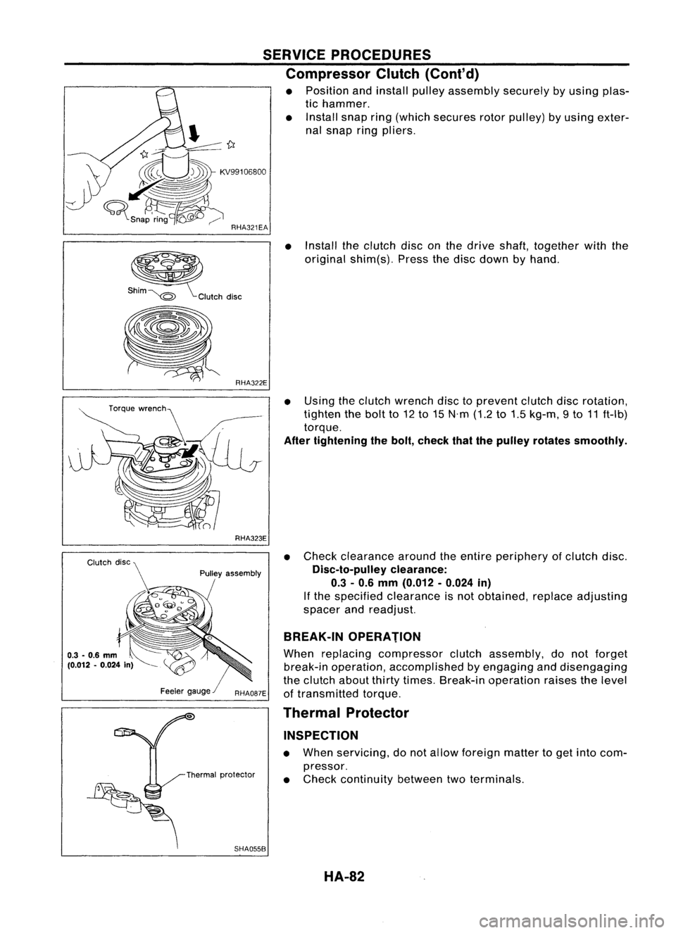
• Position andinstall pulleyassembly securelybyusing plas-
tic hammer.
• Install snapring(which secures rotorpulley) byusing exter-
nal snap ringpliers.
• Install theclutch disconthe drive shaft, together withthe
original shim(s). Pressthedisc down byhand.
RHA323E
Pulley assembly
SHA055B
•
Using theclutch wrench disctoprevent clutchdiscrotation,
tighten thebolt to12 to15 N'm (1.2to1.5 kg-m, 9to 11ft-Ib)
torque.
After tightening thebolt, check thatthepulley rotates smoothly.
• Check clearance aroundtheentire periphery ofclutch disc.
Disc-to-pulley clearance:
0.3 -0.6 mm (0.012 -0.024 in)
If the specified clearance isnot obtained, replaceadjusting
spacer andreadjust.
BREAK-IN OPERATION
When replacing compressor clutchassembly, donot forget
break-in operation, accomplished byengaging anddisengaging
the clutch aboutthirtytimes. Break-in operation raisesthelevel
of transmitted torque.
Thermal Protector
INSPECTION
• When servicing, donot allow foreign mattertoget into com-
pressor.
• Check continuity betweentwoterminals.
HA-82
Page 1485 of 1701
Ventilationairfilter
Evaporator SERVICE
PROCEDURES
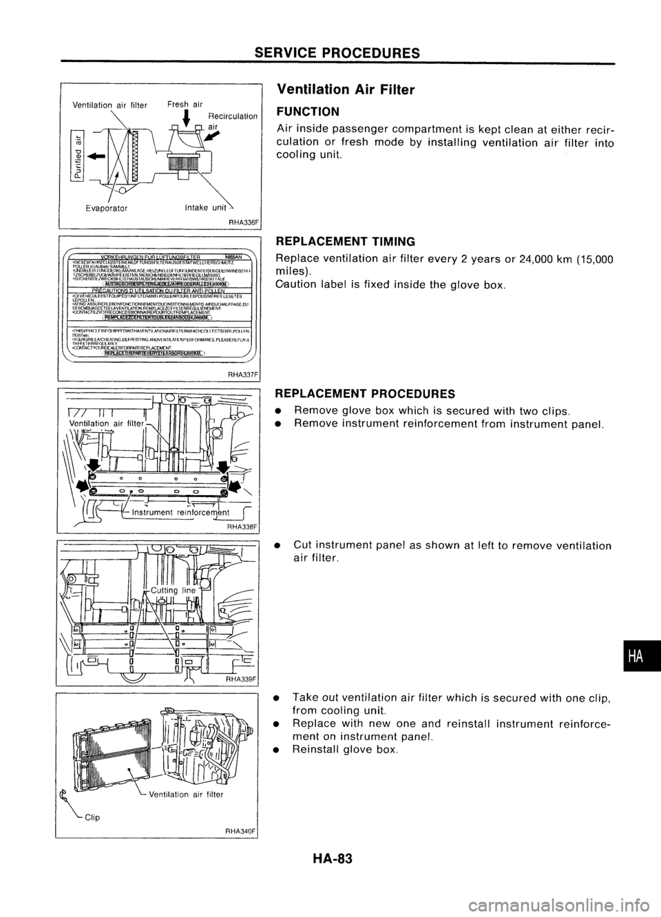
Ventilation AirFilter
FUNCTION
Air inside passenger compartment iskept clean ateither recir-
culation orfresh mode byinstalling ventilation airfilter into
cooling unit.
RHA336F REPLACEMENT TIMING
Replace ventilation airfilter every 2years or24,000 km(15,000
miles).
C-aution labelisfixed inside theglove box.
REPLACEMENT PROCEDURES
• Remove gloveboxwhich issecured withtwoclips.
• Remove instrument reinforcement frominstrument panel.
• Cut instrument panelasshown atleft toremove ventilation
air filter.
• Take outventilation airfilter which issecured withoneclip,
from cooling unit.
• Replace withnewoneand reinstall instrument reinforce-
ment oninstrument panel.
• Reinstall glovebox.
•
RHA340F HA-83
Page 1486 of 1701
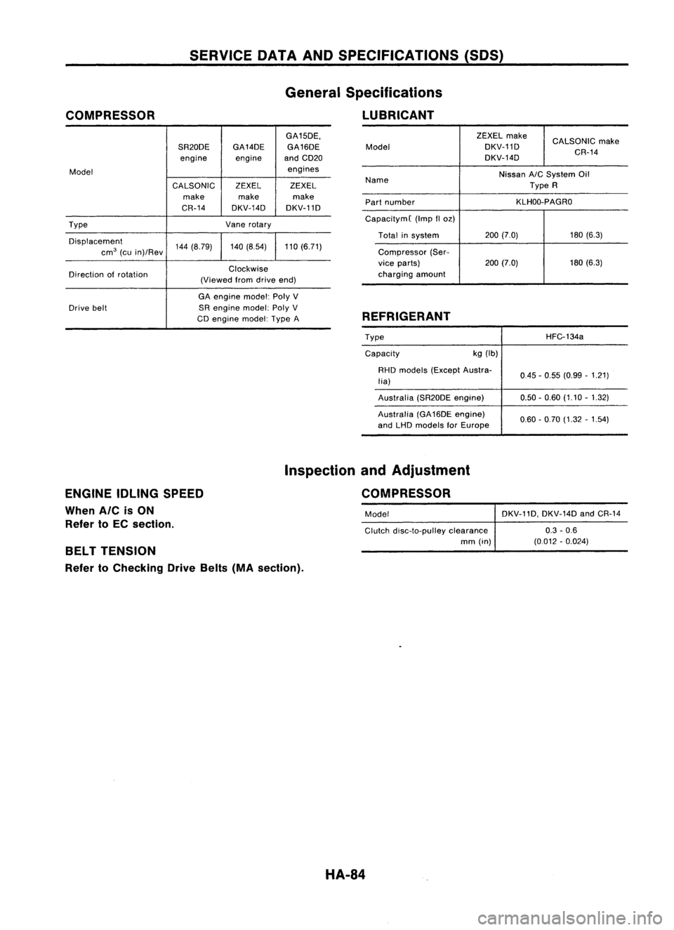
COMPRESSOR SERVICE
DATAANDSPECIFICATIONS (50S)
General Specifications
LUBRICANT
GA15DE,
SR20DE GA14DE
GA16DE
engine engineandCD20
Model engines
CALSONIC ZEXELZEXEL
make makemake
CR-14 DKV-14D DKV-11D
Type Vanerotary
Displacement 144(8.79) 140(8.54) 110(6.71)
cm
3
(cuin)/Rev
Direction ofrotation Clockwise
(Viewed fromdrive end)
GA engine model:PolyV
Drive belt SRengine model:PolyV
CD engine model:TypeA ZEXEL
make
CALSONIC make
Model DKV-11D
DKV-14D CR-14
Name Nissan
A/C
System Oil
Type R
Part number KLHOO-PAGRO
CapacitymC (Impfloz)
Total insystem 200
(7.0) 180(6.3)
Compressor (Ser-
vice parts) 200(7.0) 180
(6.3)
charging amount
REFRIGERANT
TypeCapacity kg
(Ib) HFC-134a
RHD models (Except Austra-
lia)
Australia (SR20DEengine)
Australia (GA16DE engine)
and LHD models forEurope 0.45
-0.55 (0.99 -1.21)
0.50 -0.60 (1.10 -1.32)
0.60 -0.70 (1.32 -1.54)
ENGINE IDLINGSPEED
When AICisON
Refer toEC section. Inspection
andAdjustment
COMPRESSOR
Model DKV-11D,DKV-14DandCR-14
Clutch disc-to-pulley clearance 0.3-0.6
mm (in) (0.012-0.024)
BELT TENSION
Refer toChecking DriveBelts(MAsection).
HA-84
Page 1487 of 1701
SECTION
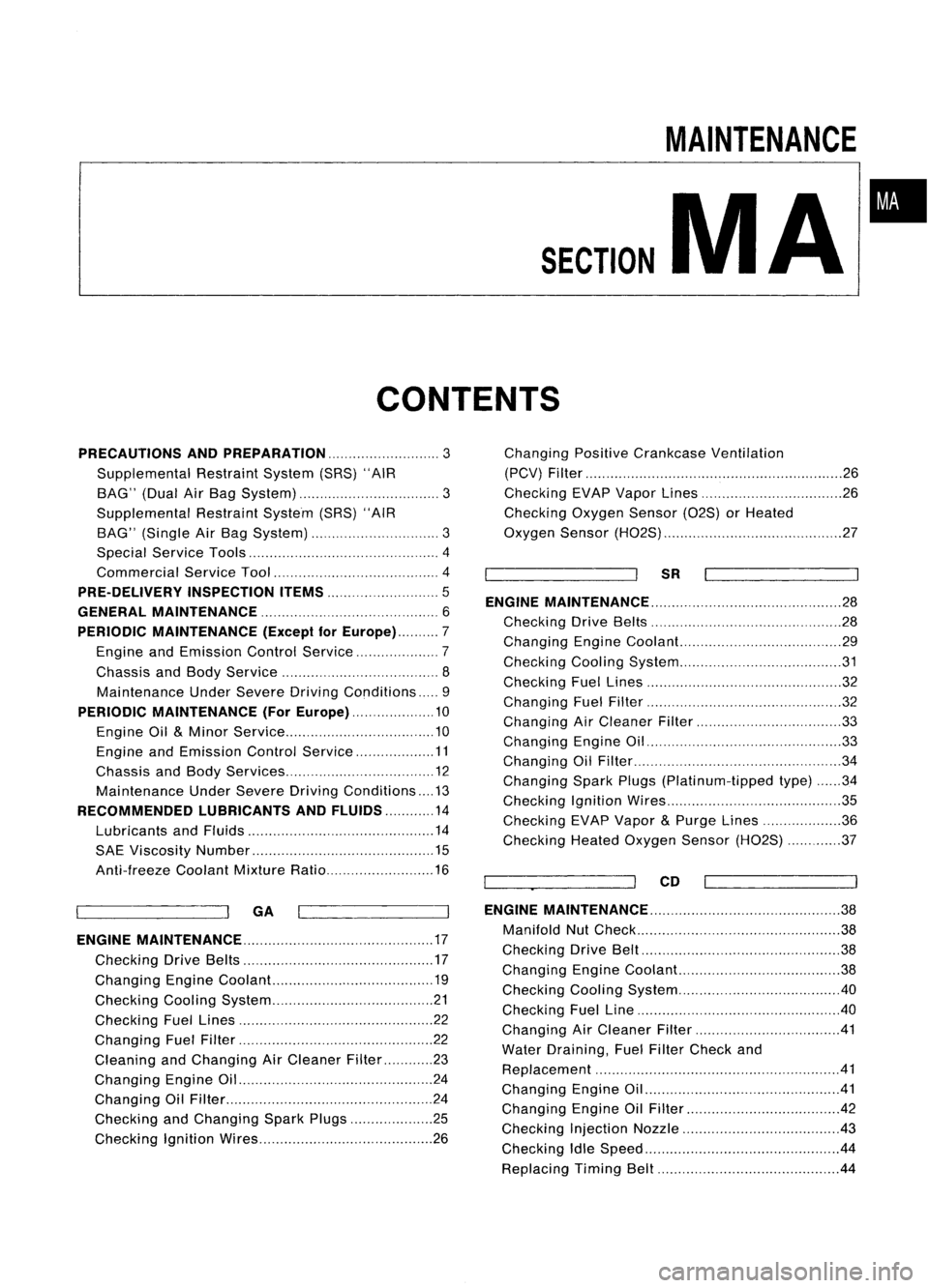
CONTENTS
MAINTENANCE
MA
•
PRECAUTIONS ANDPREPARATION
3
Supplemental RestraintSystem(SRS)"AIR
BAG" (DualAirBag System) 3
Supplemental RestraintSystem(SRS)"AIR
BAG" (Single AirBag System) 3
Special Service Tools 4
Commercial ServiceTool 4
PRE-DELIVERY INSPECTIONITEMS
5
GENERAL MAINTENANCE 6
PERIODIC MAINTENANCE (Exceptfor
Europe) 7
Engine andEmission ControlService 7
Chassis andBody Service 8
Maintenance UnderSevere DrivingConditions 9
PERIODIC MAINTENANCE (ForEurope) 10
Engine Oil
&
Minor Service 10
Engine andEmission ControlService 11
Chassis andBody Services 12
Maintenance UnderSevere Driving Conditions 13
RECOMMENDED LUBRICANTSANDFLUIDS 14
Lubricants andFluids 14
SAE Viscosity Number 15
Anti-freeze CoolantMixtureRatio 16
~ --ll
GA
I I
ENGINE MAINTENANCE 17
Checking DriveBelts 17
Changing EngineCoolant... 19
Checking CoolingSystem 21
Checking FuelLines 22
Changing FuelFilter 22
Cleaning andChanging AirCleaner Filter 23
Changing EngineOil 24
Changing OilFilter 24
Checking andChanging SparkPlugs 25
Checking IgnitionWires 26Changing
PositiveCrankcase Ventilation
(PCV) Filter 26
Checking EVAPVapor Lines 26
Checking OxygenSensor(02S)orHeated
Oxygen Sensor(H02S) 27
~ --ll
SR
I I
ENGINE MAINTENANCE 28
Checking DriveBelts 28
Changing EngineCoolant... 29
Checking CoolingSystem 31
Checking FuelLines 32
Changing FuelFilter 32
Changing AirCleaner Filter 33
Changing EngineOil 33
Changing OilFilter 34
Changing SparkPlugs(Platinum-tipped type)34
Checking IgnitionWires 35
Checking EVAPVapor
&
Purge Lines 36
Checking HeatedOxygen Sensor(H02S) 37
~_~ ..-JI
CD
I I
ENGINE MAINTENANCE
38
Manifold NutCheck 38
Checking DriveBelt 38
Changing EngineCoolant. 38
Checking CoolingSystem .40
Checking FuelLine .40
Changing AirCleaner Filter 41
Water Draining, FuelFilter Check and
Replacement 41
Changing EngineOil .41
Changing EngineOilFilter 42
Checking InjectionNozzle 43
Checking IdleSpeed .44
Replacing TimingBelt 44
Page 1488 of 1701
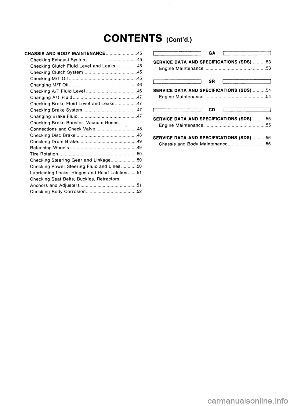
CONTENTS(Cont'd.)
CHASSIS ANDBODY MAINTENANCE 45
Checking ExhaustSystem .45
Checking ClutchFluidLevel andLeaks .45
Checking ClutchSystem .45
Checking MfTOil .45
Changing MfTOil 46
Checking
AfT
Fluid Level .46
Changing
AfT
Fluid .47
Checking BrakeFluidLevel andLeaks 47
Checking BrakeSystem .47
Changing BrakeFluid .47
Checking BrakeBooster, VacuumHoses,
Connections andCheck Valve ~48
Checking DiscBrake .48
Checking DrumBrake .49
Balancing Wheels 49
Ti re Rotation 50
Checking SteeringGearandLinkage 50
Checking PowerSteering FluidandLines 50
Lubricating Locks,Hinges andHood Latches 51
Checking SeatBelts, Buckles, Retractors,
Anchors andAdjusters 51
Checking BodyCorrosion 52
GA
SERVICE DATAANDSPECIFICATIONS
(505)53
Engine Maintenance 53
SR
SERVICE DATAANDSPECIFICATIONS
(505)54
Engine Maintenance 54
CD
SERVICE DATAANDSPECIFICATIONS
(505)55
Engine Maintenance 55
SERVICE DATAANDSPECIFICATIONS
(505)56
Chassis andBody Maintenance 56
Page 1489 of 1701
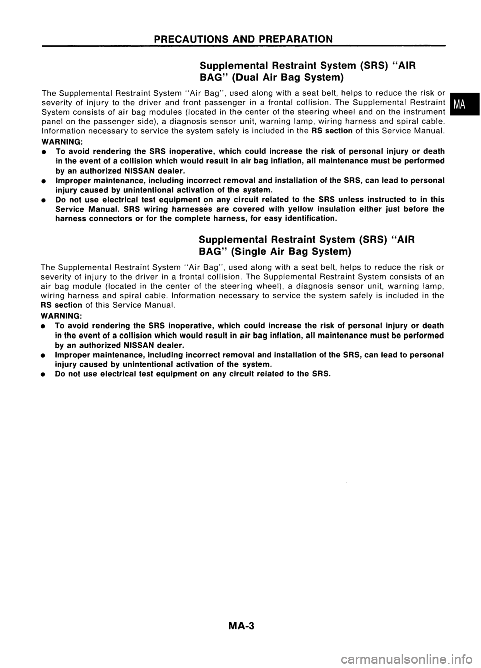
PRECAUTIONSANDPREPARATION
Supplemental RestraintSystem(SRS)"AIR
BAG" (DualAirBag System)
The Supplemental RestraintSystem"AirBag", usedalong withaseat belt,helps toreduce therisk or•
severity ofinjury tothe driver andfront passenger inafrontal collision. TheSupplemental Restraint
i
System consists ofair bag modules (locatedinthe center ofthe steering wheelandonthe instrument
panel onthe passenger side).adiagnosis sensorunit,warning lamp,wiring harness andspiral cable.
Information necessarytoservice thesystem safelyisincluded inthe
RSsection
ofthis Service Manual.
WARNING:
• Toavoid rendering theSRS inoperative, whichcouldincrease therisk ofpersonal injuryordeath
in the event ofacollision whichwould resultinair bag inflation, allmaintenance mustbeperformed
by an authorized NISSANdealer.
• Improper maintenance, includingincorrectremovalandinstallation ofthe SRS, canlead topersonal
injury caused byunintentional activationofthe system.
• Donot use electrical testequipment onany circuit related tothe SRS unless instructed tointhis
Service Manual. SRSwiring harnesses arecovered withyellow insulation eitherjustbefore the
harness connectors orfor the complete harness,foreasy identification.
Supplemental RestraintSystem(SRS)"AIR
BAG" (Single AirBag System)
The Supplemental RestraintSystem"AirBag", usedalong withaseat belt,helps toreduce therisk or
severity ofinjury tothe driver inafrontal collision. TheSupplemental RestraintSystemconsists ofan
air bag module (located inthe center ofthe steering wheel),adiagnosis sensorunit,warning lamp,
wiring harness andspiral cable. Information necessarytoservice thesystem safelyisincluded inthe
RS section
ofthis Service Manual.
WARNING:
• Toavoid rendering theSRS inoperative, whichcouldincrease therisk ofpersonal injuryordeath
in the event ofacollision whichwould resultinair bag inflation, allmaintenance mustbeperformed
by an authorized NISSANdealer.
• Improper maintenance, includingincorrectremovalandinstallation ofthe SRS, canlead topersonal
injury caused byunintentional activationofthe system.
• Donot use electrical testequipment onany circuit related tothe SRS.
MA-3
Page 1490 of 1701
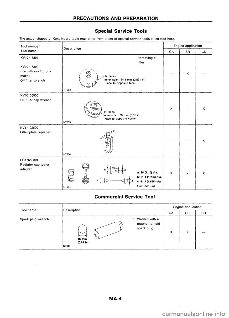
PRECAUTIONSANDPREPARATION
Special Service Tools
The actual shapes ofKent-Moore toolsmaydiffer fromthose ofspecial service toolsillustrated here.
Tool number Engine
application
Tool name Description
GASRCD
KV10115801 Removingoil
filter
KV10115800
(Kent-Moore Europe
~14"'"
-
X
-
make)
Oil filter wrench Inner
span:
64.3
mm
(2.531
in)
(Face toopposite face)
NT362
KV10105900
Oil filter capwrench
~
X
-
X
15
faces,
Inner span: 80mm
(3.15
in)
(Face toopposite corner)
NT555
KV11102600
Lifter platereplacer
1
-
-
X
NT556
EG17650301 Radiator captester
~
ct~4b
adapter
~
"
a:
28
(1.10) dia.
XX X
a+ciP q]J+a
b:
31.4 (1.236) dia.
c: 41.3 (1.626) dia.
I
NT564
Unit:
mm(in)
Commercial ServiceTool
Engineapplication
Tool name Description
GASRCD
Spark plugwrench
.
Wrench witha
Q
0
magnet
tohold
spark plug
XX
-
16
mm
(0.63 In)
NT047
MA.4