NISSAN ALMERA N15 1995 Service Manual
ALMERA N15 1995
NISSAN
NISSAN
https://www.carmanualsonline.info/img/5/57349/w960_57349-0.png
NISSAN ALMERA N15 1995 Service Manual
Trending: spare key, engine oil capacity, brake, radiator, refrigerant type, Head, oil level
Page 1471 of 1701
SERVICEPROCEDURES
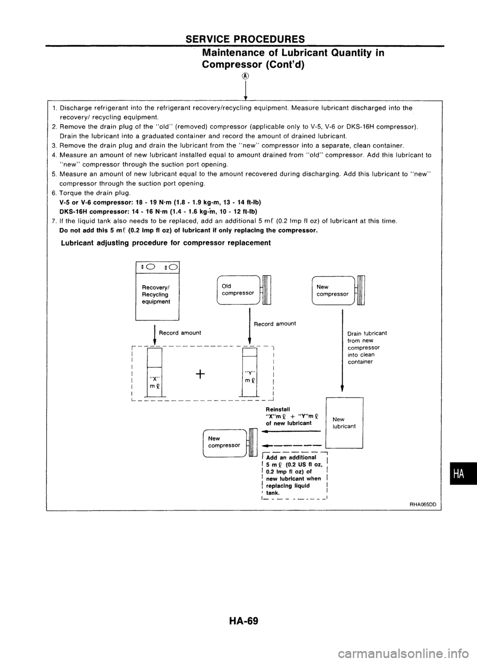
Maintenance ofLubricant Quantityin
Compressor (Cont'd)
@
1. Discharge refrigerant intotherefrigerant recovery/recycling equipment.Measurelubricantdischarged intothe
recovery/ recyclingequipment.
2. Remove thedrain plugofthe "old" (removed) compressor (applicableonlytoV-5, V-6orDKS-16H compressor).
Drain thelubricant intoagraduated containerandrecord theamount ofdrained lubricant.
3. Remove thedrain pluganddrain thelubricant fromthe"new" compressor intoaseparate, cleancontainer.
4. Measure anamount ofnew lubricant installedequaltoamount drained from"old" compressor. Addthislubricant to
"new" compressor throughthesuction portopening.
5. Measure anamount ofnew lubricant equaltothe amount recovered duringdischarging. Addthislubricant to"new"
compressor throughthesuction portopening.
6. Torque thedrain plug.
V.5 orV-6 compressor: 18-19 N'm (1.8-1.9 kg-m, 13-14 ft-Ib)
DKS.16H compressor: 14-16 N'm (1.4-1.6 kg-in, 10-12 ft-Ib)
7. Ifthe liquid tankalso needs tobe replaced, addanadditional 5mC (0.2 Imp IIoz) oflubricant atthis time.
Do not add this5m C(0.2 ImpIIoz) oflubricant ifonly replacing thecompressor.
Lubricant adjustingprocedure forcompressor replacement
DO DO
Oldcompressor
Recovery/
Recycling
eqUipment
!
Roo'"
,m,,",
1
R,,,,'
,moo",
,--------------------,
I I
I I
I + I
I "Y"I
I "X"
mQ
I
I
mQ
I
I I
L ~
New
compressor
Drainlubricant
from new
compressor
into clean
container
------ L-...
.J
New
compressor
HA-69
Reinstall
"X"m
Q
+
"Y"m
Q
of new lubricant
-.-------
fAdda;-addition;;
"I
15m
Q
(0.2 USfl
Ol,
I 0.2
Imp
fl
Ol)
of
I
I new lubricant when
I
!
replacing liquid I
, tank. I
1- -__ I
New
lubricant
RHA065DD
•
Page 1472 of 1701
SERVICEPROCEDURES
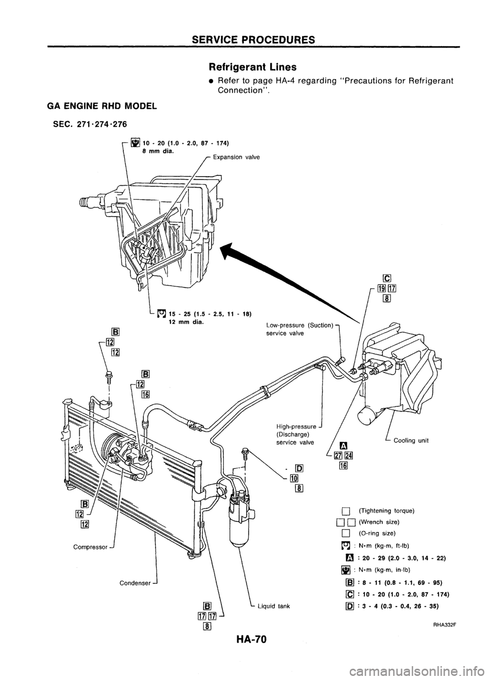
Refrigerant Lines
• Refer topage HA-4regarding "Precautions forRefrigerant
Connection" .
GA ENGINE
RHO
MODEL
SEC. 271.274.276
fil10'20(1.0 .2.0, 87.174)
8
mm
dia.
Liquidtank
Condenser Expansion
valve
[O;J
15-25 (1.5 -2.5, 11-18)
12
mm
dia.
Low-pressure(Suction)
service valve
o
(Tightening torque)
o
0
(Wrench size)
o
(O-ring size)
[O;J :
N.m (kg-m, ft-Ib)
rn :
20 •29 (2.0 •3.0, 14-22)
fiI :
N.m (kg-m, in-Ib)
IBl :
8 •11 (0.8 -1.1, 69-95)
[C] :
10 -20 (1.0 -2.0, 87-174)
~ :3 -4 (0.3 -0.4, 26-35)
RHA332F
HA-70
Page 1473 of 1701
S~~~~:~::--_~S~ER ~V~1~C~E~P;.R;O~C¥E¥,D~U~fo;;r.:i) _
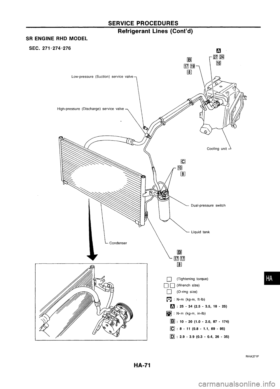
R ENGINE RHDMO Ref" RES
5
DEL
ngerant
L"
EC. 271.274 '276
mes(Cont' d)
Low-pressure (Suct'
Ion)
se'
rVlce valve
High-pressure (0'Ischarg )
e service valve
Coolingunit
Dual-pressure switch
Liquid tank
Condenser
o
(Tightening t
o
orque)
o
(Wrench size)
o
(D-ring size)
~: N'm(k
g-m,
ft-Ib)
r.:.1 :
25 -34 (
IiiiI
2.5-3.5 18
~ :N.m ( ,-25)
kg-m, in-Ib)
(SJ :
10 -20 (1
'Cl .
.0-2.0, 87-174)
~ .8 -11 (0
.8
-1.1 69
1)1 . '-95)
lMJ .2.9 .3 9 (
. 0.3 -04 26
., -35)
RHA371F
HA-71
•
Page 1474 of 1701
SERVICEPROCE
R
f•
DURES
e ngerant
L.
mes (Cont'd)
CD ENGINE RHOMODEL
SEC. 271'274-276
iii
10-20 (1.0 -2
8
mm
dia. .0,87-174)
Expansion valve
Liquid tank
[SJ
\~
il!1d
I
I
Compressor Condenser
[O.J
15-25 (1.5 -2
12
mm
d' .5,11-18)
la.
Low-pressure (
service valveSuction) Hi~h-pressure
(Discharge)
service valve
D
(Tightening t
DO orque)
(Wrench size)
o
(O-ring size)
[O.J :
N'm (k
g-m,
ft-Ib)
a :
20 -29 (20
iii :
N'm .-3.0, 14-22)
(kg-m, in-Ib)
[SJ :
8 -11 (0.8 -1
ICl :
10 .1,69-95)
- 20 (1.0 •2
[Q] :
3 _4 .0,87-174)
(0.3 -04 26
.,
•35)
RHA333F
HA-72
Page 1475 of 1701
SERVICEPROCEDURES
Refrigerant Lines(Cont'd)
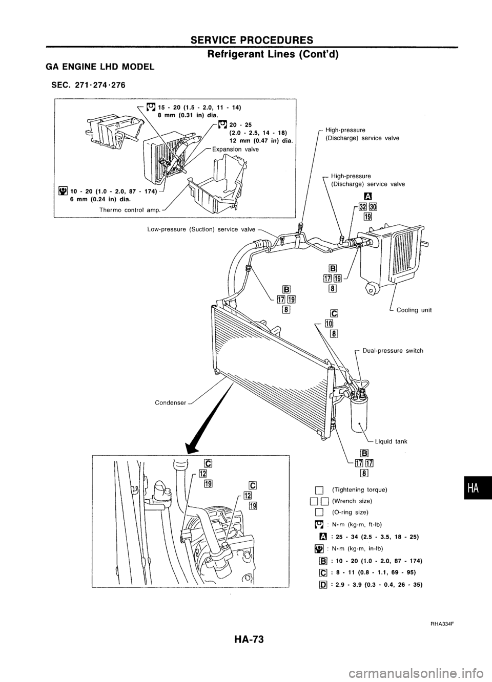
GA ENGINE lHDMODEL
SEC. 271.274.276
Low-pressure (Suction)servicevalve
~
10-20 (1.0 -2.0, 87-174)
6 mm (0.24 in)dia.
Thermo controlamp.
•
Dual-pressure
switch
~ Liquid tank
High-pressure
(Discharge) servicevalve
High-pressure
(Discharge) servicevalve
o
(Tightening torque)
D D (Wrench size)
D (O-ring size)
~ :N'm (kg-m, ft-lb)
~ :25 -34 (2.5 -3.5, 18-25)
~ :N'm (kg-m, in-Ib)
rm :
10 -20 (1.0 -2.0, 87-174)
~ :8 •11 (0.8 •1.1, 69•95)
~ :2.9 •3.9 (0.3 -0.4, 26•35)
~
15•20 (1.5 -2.0, 11-14)
~ 8
mm
(0.31
in)
die.
___ ==- - ~
20-25
(2.0 -2.5, 14-18)
."""\ ~t;,
12mm (0.47 in)dia.
Expansion valve
RHA334F
HA-73
Page 1476 of 1701
SERVICEPROCEDURES
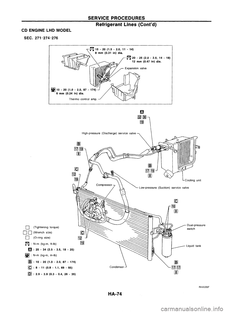
Refrigerant Lines
(Cont'd)
CD ENGINE LHDMODEL
SEC. 271'274'276
[O.J
15. 20(1.5 -2.0, 11-14)
8
mm
(0.31
in)
dia.
[O.J
20-25 (2.0 -2.5, 14-18)
12 mm (0.47 in)dia.
~ 10•20 (1.0 -2.0, 87•174)
6 mm (0.24 in)dia.
Thermo controlamp.
High-pressure (Discharge)servicevalve
o
(Tightening torque)
o
0
(Wrench size)
o
(O-ring size)
[O.J :
N'm (kg-m, It-Ib)
B :
25 -34 (2.5 -3.5, 18-25)
~ :N'm (kg-m, in-Ib)
[SJ
:10 -20 (1.0 -2.0,87 -174)
[Q :
8 -11 (0.8 -1.1, 69-95)
[Q] :
2.9 •3.9 (0.3 -0.4, 26-35)
HA-74
Cooling
unit
Low-pressure (Suction)service
valve
Liquid tank
RHA335F
Page 1477 of 1701
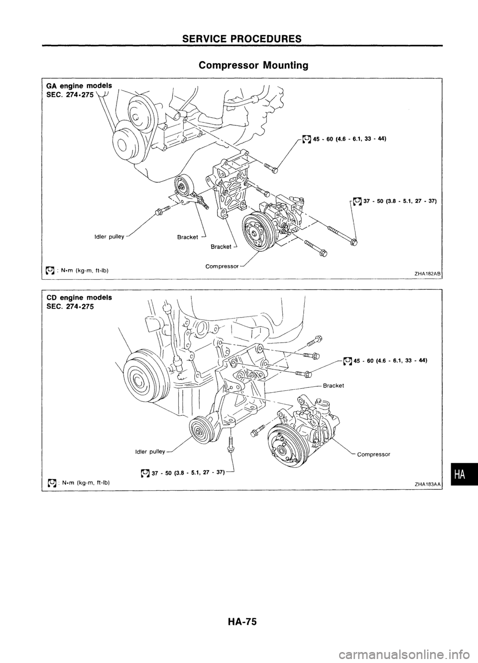
GAengine models
SEC.
274.275
~ :N.m (kg-m, ft-Ib)
CD engine models
SEC.
274.275
~ :N.m (kg-m, ft-Ib)
SERVICE
PROCEDURES
Compressor Mounting
HA-75 ZHA182AB
ZHA183AA •
Page 1478 of 1701
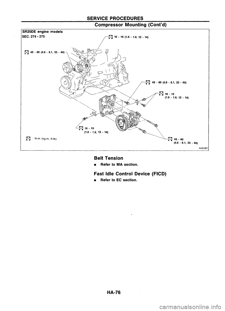
SR20DEenginemodels
SEC.
274.275
~ :N.m (kg-m, ft-Ib)
SERVICE
PROCEDURES
Compressor Mounting(Cont'd)
~ 16•19 (1.6 •1.9, 12•14)
~ 45-60 (4.6 -6.1, 33•44)
~45.60 (4.6-6.1, 33•44)
Belt Tension
• Refer toMA section.
Fast IdleControl Device(FICO)
• Refer toEC section.
HA-76 AHA387
Page 1479 of 1701
SERVICEPROCEDURES
Compressor -Model DKV-11D andDKV-14D
(ZEXEL make)
SHA927DB
SEC.
274
Clutchdisc ~4
-6
(0.4 -0.6, 35•52)
Thermalprotector
~ 15-18 (1.5 -1.8, 11•13)
~ :N'm (kg-m, in-Ib)
~ :N'm (kg-m, ft-Ib)
Drive plate
Shim SHA098EA Compressor
Clutch
REMOVAL
• When removing centerbolt,holdclutch discwithclutch disc
wrench.
• Remove thedrive plateusing ToolKV99232340.
Insert holder's threepinsintothedrive plate. Rotate the
holder clockwise tohook itonto theplate. Then, tighten the
center bolttoremove thedrive plate.
When tightening thecenter bolt,insert around bar
(screwdriver, etc.)between twoofthe pins (asshown inthe
left-hand figure)toprevent driveplaterotation. Afterremov-
ing the drive plate, remove theshims fromeither thedrive
shaft orthe drive plate.
HA-77
•
Page 1480 of 1701
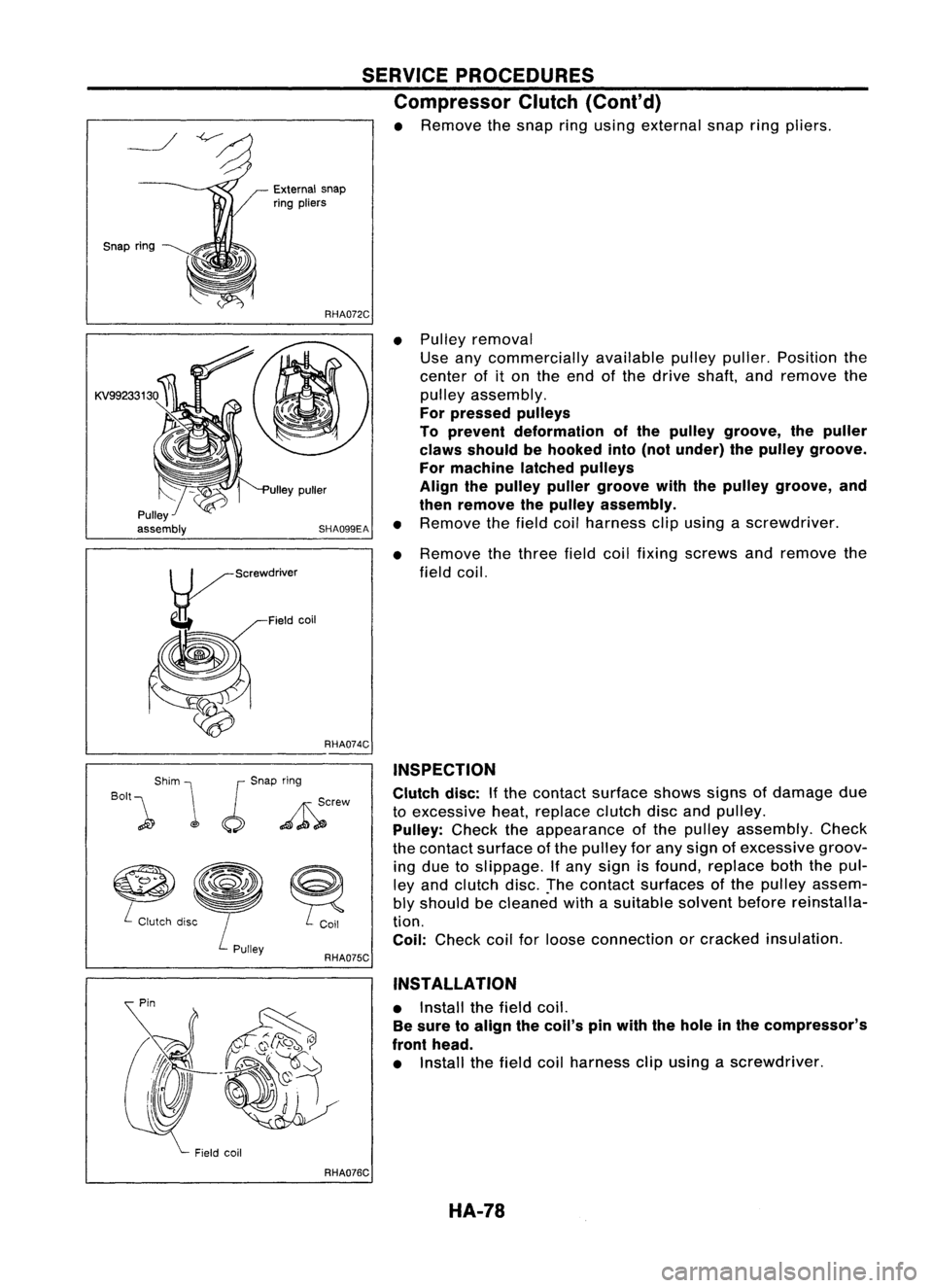
•Pulley removal
Use anycommercially availablepulleypuller. Position the
center ofiton the end ofthe drive shaft, andremove the
pulley assembly.
For pressed pulleys
To prevent deformation ofthe pulley groove, thepuller
claws should behooked into(not under) thepulley groove.
For machine latchedpulleys
Align thepulley pullergroove withthepulley groove, and
then remove thepulley assembly.
• Remove thefield coilharness clipusing ascrewdriver.
• Remove thethree fieldcoilfixing screws andremove the
field coil.
SERVICE
PROCEDURES
Compressor Clutch(Cont'd)
• Remove thesnap ringusing external snapringpliers.
RHA072C
SHA099EA
External
snap
ring pliers
ulley puller
~/S"'wd""'"
g-
Fieldcoil
Snap
ring
KV99233130
RHA074C
Shim
J
Snap ring
BOll\
1
JJ _
~crew
~
~
L
Clutch disc
RHA075CINSPECTION
Clutch disc:Ifthe contact surface showssignsofdamage due
to excessive heat,replace clutchdiscandpulley.
Pulley: Checktheappearance ofthe pulley assembly. Check
the contact surface ofthe pulley forany sign ofexcessive groov-
ing due toslippage. Ifany sign isfound, replace boththepul-
ley and clutch disc.!hecontact surfaces ofthe pulley assem-
bly should becleaned withasuitable solventbeforereinstalla-
tion.
Coil: Check coilforloose connection orcracked insulation.
INSTAllATION
• Install thefield coil.
Be sure toalign thecoil's pinwith thehole inthe compressor's
front head.
• Install thefield coilharness clipusing ascrewdriver.
RHA076C HA-78
Trending: buttons, EL-32, USB port, spare tire, tire size, high beam, EL-137

