sensor NISSAN ALMERA N15 1995 Service Manual
[x] Cancel search | Manufacturer: NISSAN, Model Year: 1995, Model line: ALMERA N15, Model: NISSAN ALMERA N15 1995Pages: 1701, PDF Size: 82.27 MB
Page 854 of 1701
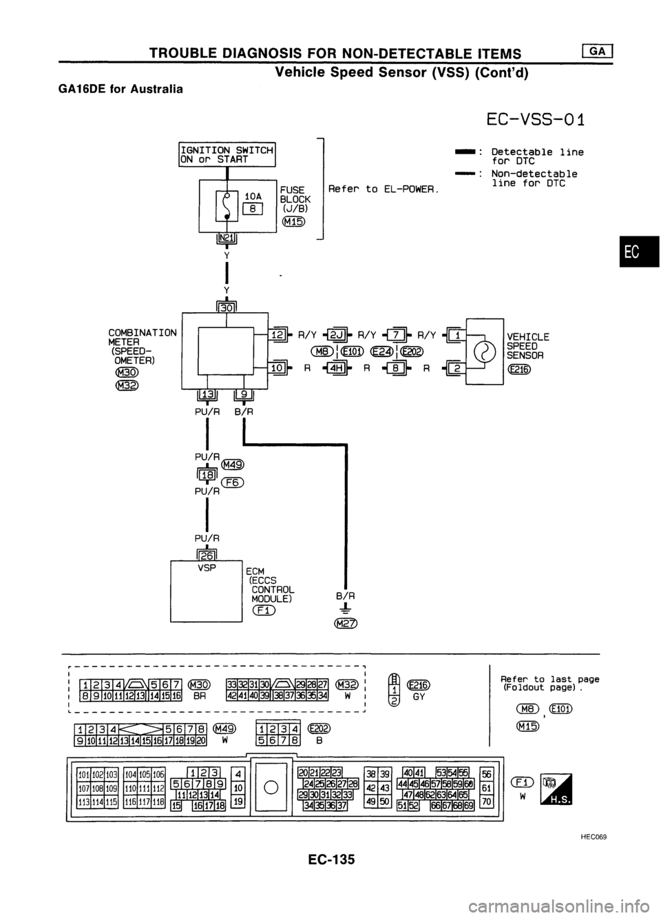
TROUBLEDIAGNOSIS FORNON-DETECTABLE ITEMS
Vehicle SpeedSensor (VSS)(Conl'd)
GA 16DE forAustralia
EC-VSS-01
~ R/Y~~ R/Y,
U-
R/Y~{1VEHICLE
~I~ ~I~ )
SPEED
~ I
'l::.!Q!, ~
J~
C
SENSOR
~ R,~ R
'U-
R{] ~
IGNITION
SWITCH
ON or START
10A
[]]
•
Detectable
line
for DTC
Non-detectable line forDTC
-:
-:
B/R
-!-
~
Refer
toEL-PDWER.
FUSE
BLOCK
(JIB)
(M15)
ECM (ECCS
CONTROL
MODULE)
(ill
~
PU/R
I
PU/RIGM'l\
r=b,~
I~I@
PU/R
I
PU/R
1~61
VSP
COMBINATION
METER (SPEED-OMETER)
~
@
Refertolast page
(Foldout page).
~~
~ GY
@
Fff2T3T4j
(E202)
w
IID:illIID
B
104 105106
110 111
112
116 117
11B
101
102 103
107 10B 109
113 114
115
~---------------------------------,
L ~
HEC069
EC-135
Page 855 of 1701
TROUBLEDIAGNOSIS FORNON-DETECTABLE ITEMS
@!J
Vehicle SpeedSensor (VSS)(Conl'd)
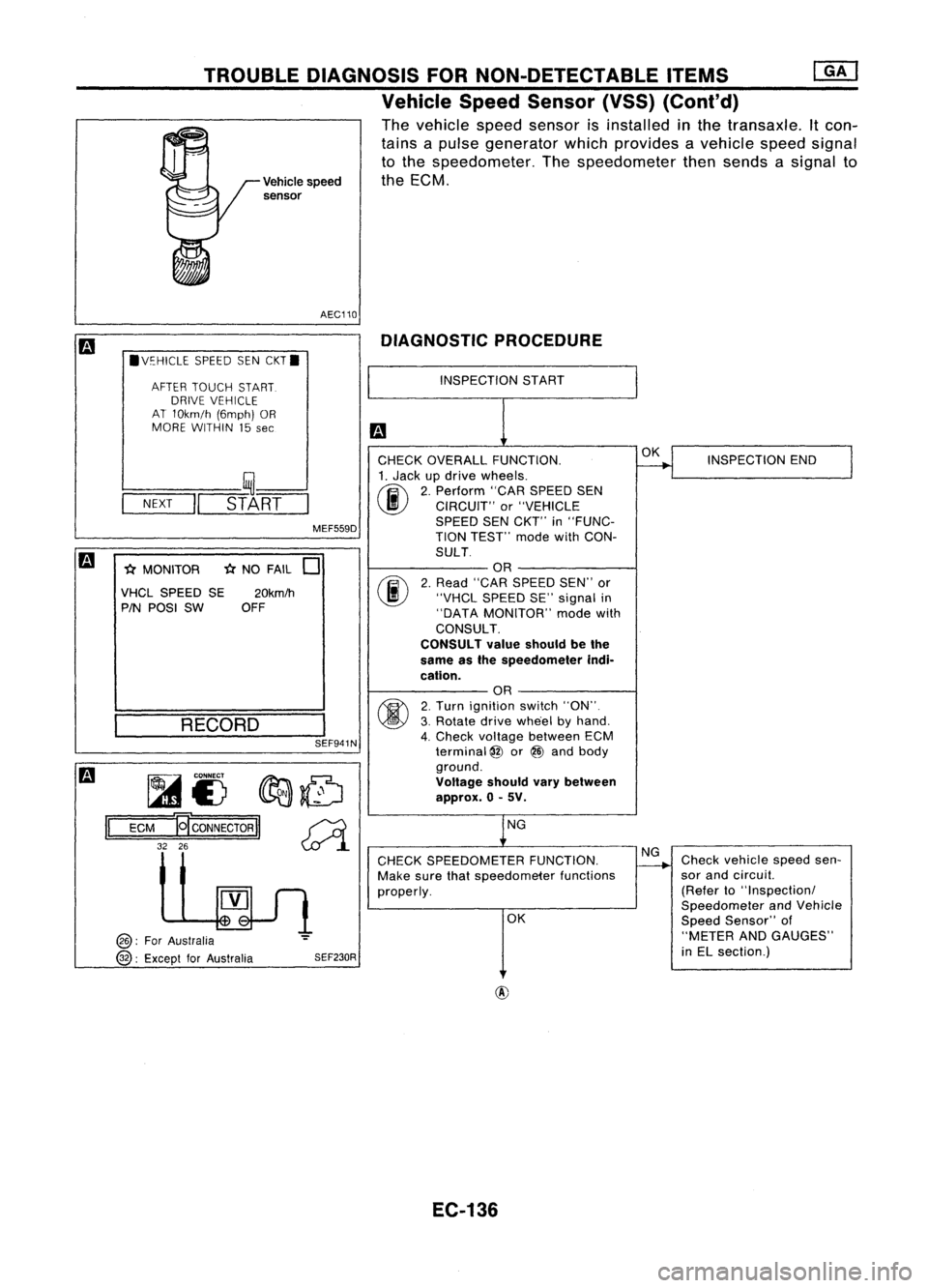
The vehicle speedsensor isinstalled inthe transaxle. Itcon-
tains apulse generator whichprovides avehicle speedsignal
to the speedometer. Thespeedometer thensends asignal to
Vehicle speed theECM.
sensor
AEC110 DIAGNOSTIC PROCEDURE
.V~HICLE SPEEDSENCKT.
AFTER TOUCH START.
DRIVE VEHICLE
AT 10km/h (6mph)OR
MORE WITHIN 15
see
INSPECTION
START
SEF941N
-(;(
NO FAIL
0
fijf.....
CONNECT
fIr:J:J:.~
1A1£) ~~
ECM
19'
CONNECTOR
II~
32 26
~l
INSPECTION
END
Check vehicle speedsen-
sor and circuil.
(Refer to"Inspectionl
Speedometer andVehicle
Speed Sensor" of
"METER ANDGAUGES"
in EL section.)
OK
NG
OK
NG
CHECK SPEEDOMETER FUNCTION.
Make surethatspeedometer functions
properly.
CHECK
OVERALL FUNCTION.
1. Jack updrive wheels.
(ij\
2.Perform "CARSPEED SEN
~ CIRCUIT" or"VEHICLE
SPEED SENCKT'" in"FUNC-
TION TEST'" modewithCON-
SULT OR
2. Read "CAR SPEED SEN"'or
"VHCL SPEED SE"signal in
"DATA MONITOR" modewith
CONSULT.
CONSULT valueshould bethe
same asthe speedometer indi-
cation. OR
2. Turn ignition switch"ON".
3. Rotate drivewhe'el byhand.
4. Check voltage between ECM
terminal
@
or@ and body
ground.
Voltage shouldvarybetween
approx. 0-5V.
SEF230R
MEF559D
20km/h
OFF
RECORD
l----
__ ,~--'
-N-EX-T
-II
STA-RT-
-(;( MONITOR
VHCL SPEED SE
PIN POSI SW
@:
ForAustralia
@:
Except forAustralia
II
EC-136
Page 856 of 1701
TROUBLEDIAGNOSIS FORNON-DETECTABLE ITEMS
Vehicle SpeedSensor (VSS)(Cont'd)
m
Models withtachometer
II
ECM
@ :For Australia
@ :Except forAustralia
Models without tachometer
II
ECM
@
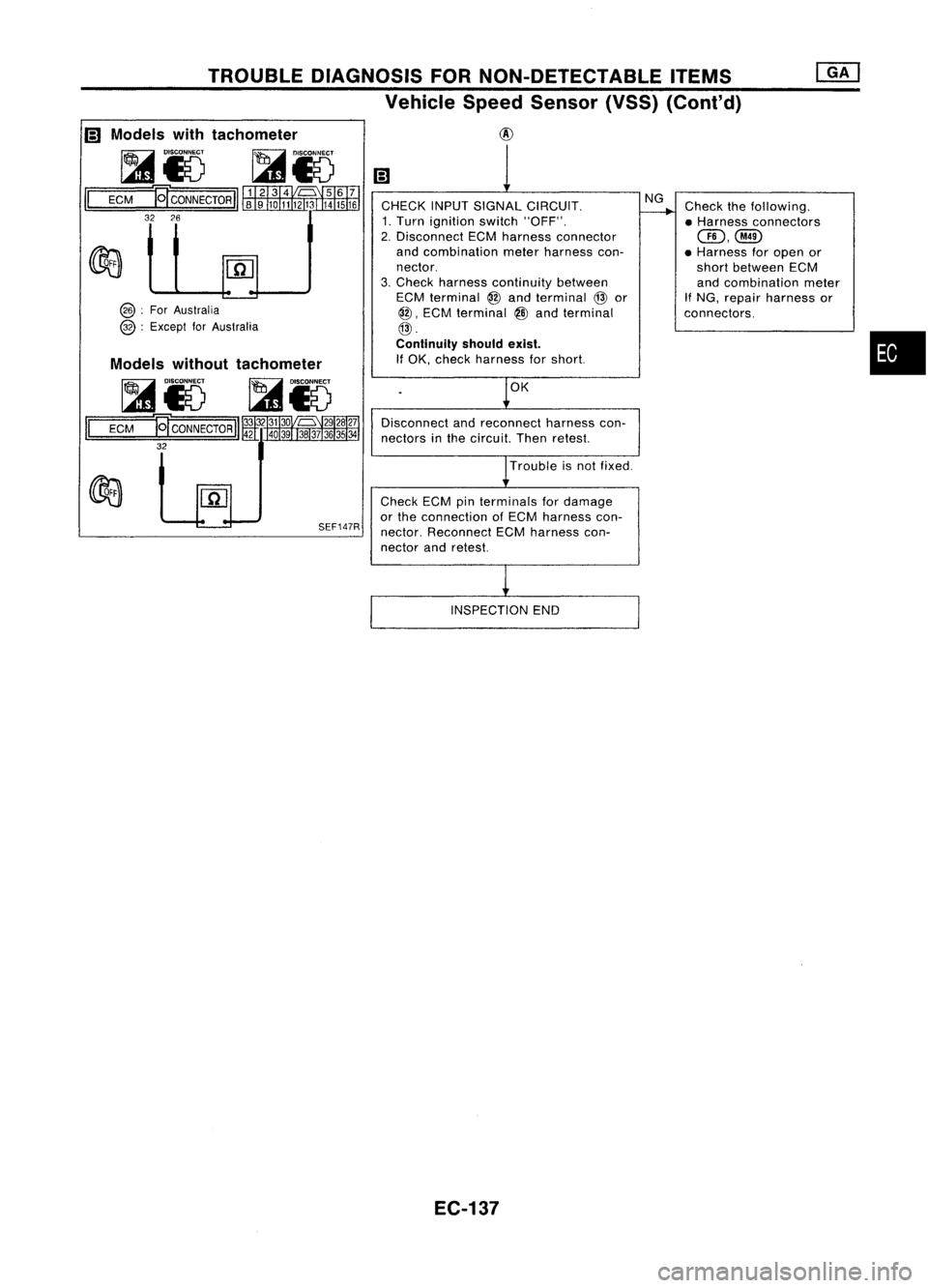
CHECK INPUTSIGNAL CIRCUIT.
1. Turn ignition switch"OFF".
2. Disconnect ECMharness connector
and combination meterharness con-
nector.
3. Check harness continuity between
ECM terminal
@
and terminal
@
or
@,
ECM terminal
@
and terminal
@.
Continuity shouldexist.
If OK, check harness forshort.
OK
Disconnect andreconnect harnesscon-
nectors inthe circuit. Thenretest.
Trouble isnot fixed.
NG
Check thefollowing.
• Harness connectors
GD,@
• Harness foropen or
short between ECM
and combination meter
If
NG, repair harness or
connectors.
•
SEF147R
Check
ECMpinterminals fordamage
or the connection ofECM harness con-
nector. Reconnect ECMharness con-
nector andretest.
INSPECTION END
EC-137
Page 864 of 1701
TROUBLEDIAGNOSIS FORNON-DETECTABLE ITEMS
Fuel Pump
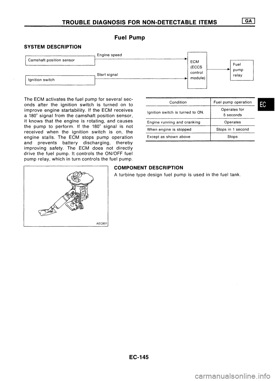
SYSTEM DESCRIPTION
Enginespeed
Camshaft positionsensor
Startsignal
Ignition switch
The ECM activates thefuel pump forseveral sec-
onds aftertheignition switchisturned onto
improve enginestartability. Ifthe ECM receives
a 180
0
signal fromthecamshaft positionsensor,
it knows thattheengine isrotating, andcauses
the pump toperform. Ifthe 180
0
signal isnot
received whentheignition switchison, the
engine stalls.TheECM stops pump operation
and prevents batterydischarging, thereby
improving safety.TheECM does notdirectly
drive thefuel pump. Itcontrols theON/OFF fuel
pump relay, which inturn controls thefuel pump.
ECM
(ECCS
control module)
Condition
Ignition switchisturned toON.
Engine running andcranking
When engine isstopped
Except asshown above Fuel
pump relay
Fuel pump operation
Operates for
5 seconds
Operates
Stops in1second
Stops
•
COMPONENT DESCRIPTION
A turbine typedesign fuelpump isused inthe fuel tank.
AEC801
EC-145
Page 869 of 1701
TROUBLEDIAGNOSIS FORNON-DETECTABLE ITEMS
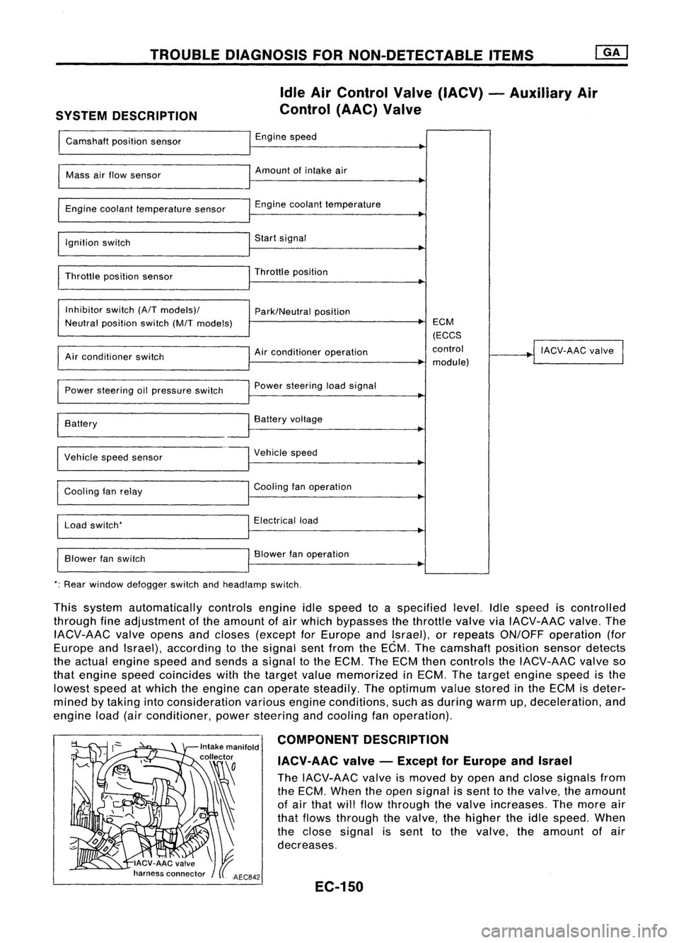
SYSTEM DESCRIPTION Idle
AirControl Valve(IACV) -Auxiliary Air
Control (AAC)Valve
Camshaft positionsensor Engine
speed
I
Mass
airflow sensor Amount
ofintake air
I
Engine coolant temperature sensor Engine
coolant temperature
~
I
Ignition switch Start
signal
I
Throttle positionsensor Throttle
position
~
I
Inhibitor switch(A/Tmodels)/
Park/Neutralposition
Neutral position switch(M/Tmodels) ECM
(ECCS
Air conditioner operation control
!
IACV-AAC valve
I
Air conditioner switch
module)
Power steering oilpressure switch Power
steering loadsignal
I
Battery
~
Battery voltage
Vehicle speedsensor Vehicle
speed
Cooling fanrelay Cooling
fanoperation
Load switch' Electrical
load
Blower fanswitch Blower
fanoperation
': Rear window defogger switchandheadlamp switch.
This system automatically controlsengineidlespeed toaspecified level.Idlespeed iscontrolled
through fineadjustment ofthe amount ofair which bypasses thethrottle valveviaIACV-AAC valve.The
IACV-AAC valveopens andcloses (except forEurope andIsrael), orrepeats ON/OFF operation (for
Europe andIsrael), according tothe signal sentfrom theECM. Thecamshaft positionsensordetects
the actual engine speedandsends asignal tothe ECM. TheECM thencontrols theIACV-AAC valveso
that engine speedcoincides withthetarget valuememorized inECM. Thetarget engine speedisthe
lowest speedatwhich theengine canoperate steadily. Theoptimum valuestored inthe ECM isdeter-
mined bytaking intoconsideration variousengineconditions, suchasduring warmup,deceleration, and
engine load(airconditioner, powersteering andcooling fanoperation).
COMPONENT DESCRIPTION
IACV-AAC valve-Except forEurope andIsrael
The IACV-AAC valveismoved byopen andclose signals from
the ECM. When theopen signal issent tothe valve, theamount
of air that willflow through thevalve increases. Themore air
that flows through thevalve, thehigher theidle speed. When
the close signal issent tothe valve. theamount ofair
decreases.
EC-150
Page 873 of 1701
Repairharness orcon-
nectors. INSPECTION
END
Check thefollowing.
• Harness connectors
QD,@orQD,
@
• 10A fuse
• Harness foropen or
short between IACV-AAC
valve andfuse
If NG, repair harness or
connectors.
NG OK
NG
OK
INSPECTION
START
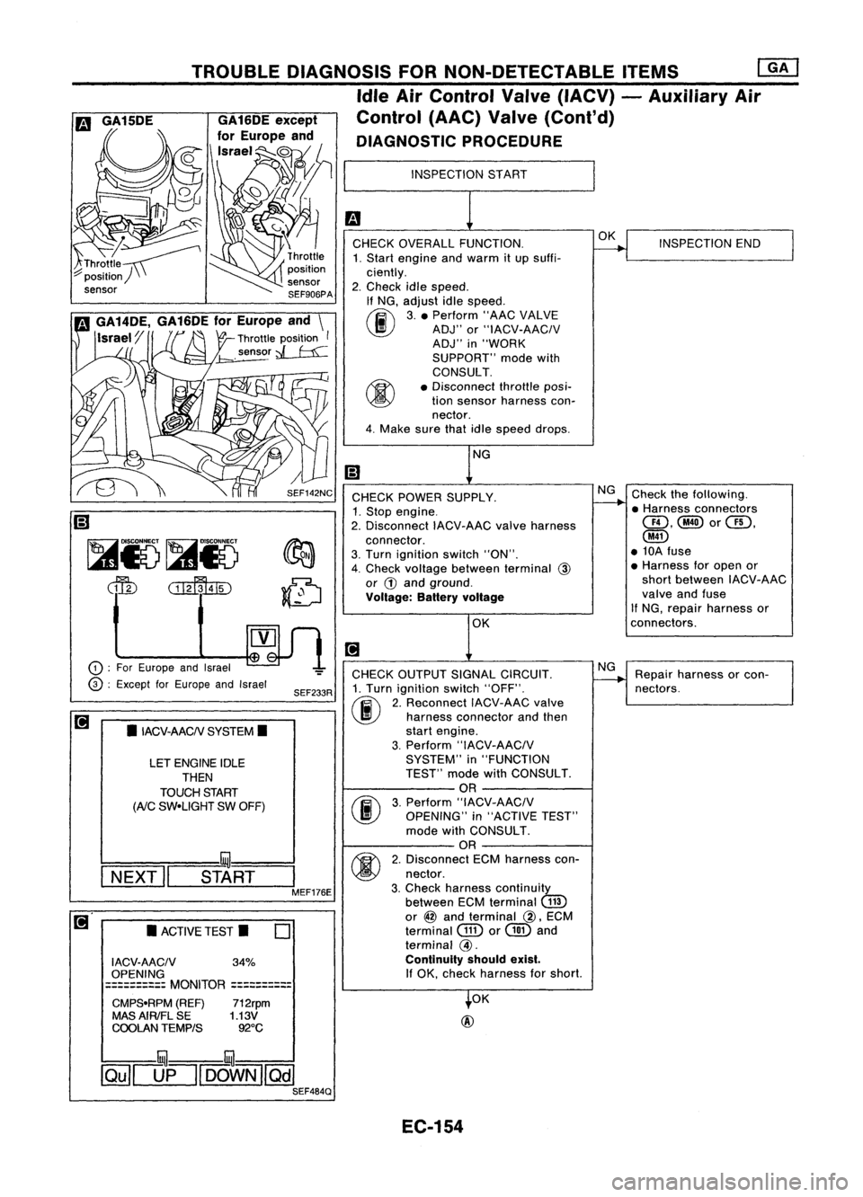
CHECK OVERALL FUNCTION.
1. Start engine andwarm itup suffi-
ciently.
2. Check idlespeed.
If NG, adjust idlespeed.
~ 3.• Perform "AACVALVE
~ ADJ"or"IACV-AACIV
ADJ" in"WORK
SUPPORT" modewith
CONSULT.
• Disconnect throttleposi-
tion sensor harness con-
nector.
4. Make surethatidlespeed drops.
OK
@
CHECK
POWER SUPPLY.
1. Stop engine.
2. Disconnect IACV-AACvalveharness
connector.
3. Turn ignition switch"ON".
4. Check voltage between terminal
@
or
G)
and ground.
Voltage: Batteryvoltage
CHECK OUTPUT SIGNALCIRCUIT.
1. Turn ignition switch"OFF".
(ij\
2.Reconnect IACV-AACvalve
~ harnessconnector andthen
start engine.
3. Perform "IACV-AACIV
SYSTEM" in"FUNCTION
TEST" modewithCONSULT.
OR
(F.I\
3.Perform "IACV-AACIV
~ OPENING" in"ACTIVE TEST"
mode withCONSULT.
OR
M
2.Disconnect ECMharness con-
~ nectar.
3. Check harness continuity
between ECMterminal
(ill)
or
@
and terminal
@,
ECM
terminal
GID
or
@
and
terminal
@.
Continuity shouldexist.
If
OK, check harness forshort.
SEF233R
SEF142NC
o
•
ACTIVE TEST.
LET
ENGINE IDLE
THEN
TOUCH START
(AiC
SW-UGHT SWOFF)
•
IACV-AACN SYSTEM.
I ACV-AACN 34%
OPENING
==========
MONITOR
==========
CMPS-RPM (REF)712rpm
MAS AIRIFL SE 1.13V
COOLAN TEMPtS 92°C
TROUBLE
DIAGNOSIS FORNON-DETECTABLE ITEMS
ffiJ
Idle AirControl Valve(IACV) -Auxiliary Air
Control (AAC)Valve(Cont'd)
DIAGNOSTIC PROCEDURE
!:::=====mul===
I
NEXT" START
I
MEF176E
CD
:
For Europe andIsrael
@ :
Except forEurope andIsrael
~
Ii)
~i5~i5
dfu
CillffuID
illU--illU
~[]fl[OOWN][Qill SEF484Q
EC-154
Page 875 of 1701
TROUBLEDIAGNOSIS FORNON-DETECTABLE ITEMS
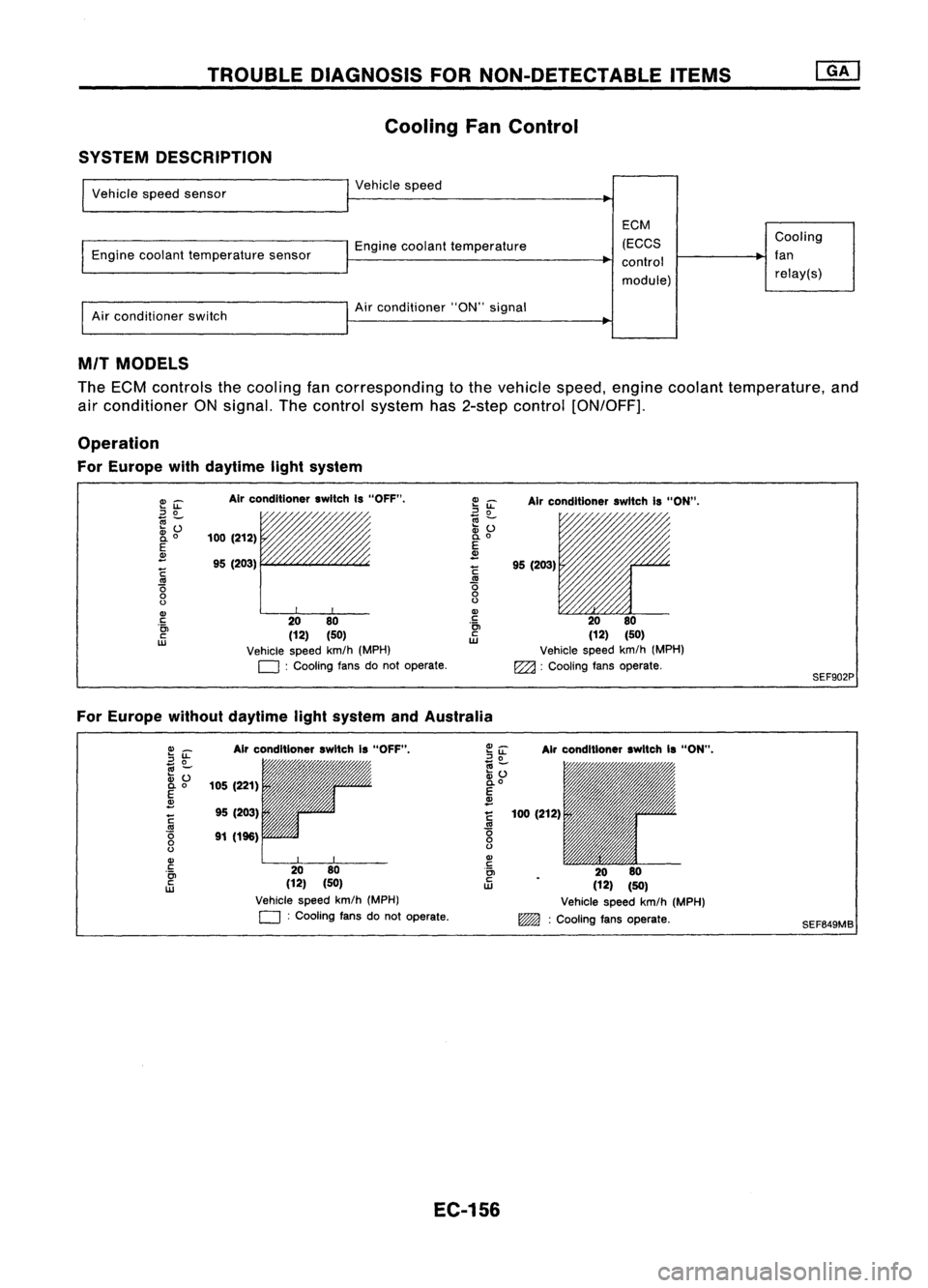
Cooling FanControl
SYSTEM DESCRIPTION
Vehicle speedsensor
Engine coolant temperature sensor
Air conditioner switch Vehicle
speed
Engine coolant temperature
Air conditioner "ON"signal
EGM
(EGGS
control
module) Gooling
fan relay(s)
MIT MODELS
The ECM controls thecooling fancorresponding tothe vehicle speed,engine coolant temperature, and
air conditioner ONsignal. Thecontrol system has2-step control [ON/OFF].
Operation
For Europe withdaytime lightsystem
E~
::J
0
~Z;
2i
o
E
~
~
'0
o
o
Gl
c
'0>
c
w
Air
conditioner switchIs"OFF".
/,
100 (212)
95 (203)
rr
20 80
(12) (50)
Vehicle speedkm/h(MPH)
D :
Cooling fansdonot operate.
~
iL
Airconditioner switchIs"ON".
~ ~ 11'l1/1~~~
:v
() /'/"
0.
0
E
~
!
95(203)
.~ 2080
ill
(12)(50)
Vehicle speedkm/h(MPH)
EZ2l :
Cooling fansoperate.
SEF902P
For Europe withoutdaytime lightsystem andAustralia
Gl_
2~
.,
-
:v ()
0.0
E
~
~
'0
o
o
Gl
c
'0>
c
w
Air
conditioner switchIs"OFF",
105 (221)
95 (203)
91 (196)
2080
(12) (50)
Vehicle speedkm/h(MPH)
D :
Cooling fansdonot operate.
Air
conditioner switchIs"ON",
100 (212)
2080
(12) (50)
Vehicle speedkm/h(MPH)
~ :Cooling fansoperate.
SEF649MB
EC-156
Page 881 of 1701
Checkcooling fanlow
speed control circuit.
(Go to
I
PROCEDURE A
I.)
Check cooling fanhigh
speed control circuit.
(Go to
I
PROCEDURE B
I.)
NG
NG
OK
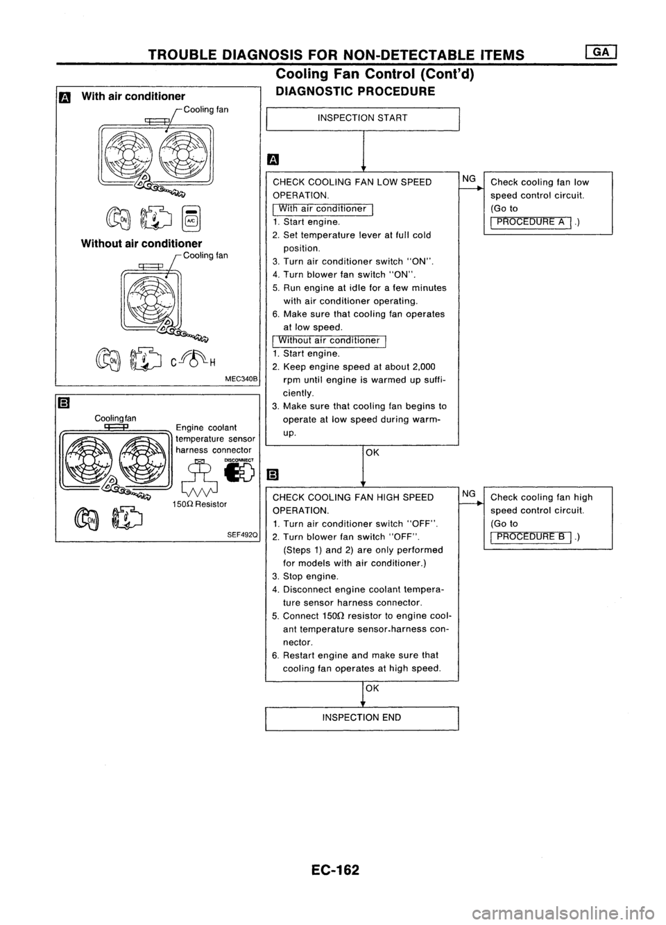
INSPECTION
START
CHECK COOLING FANLOW SPEED
OPERATION.
I
With airconditioner
I
1. Start engine.
2. Set temperature leveratfull cold
position.
3. Turn airconditioner switch"ON".
4. Turn blower fanswitch "ON".
5. Run engine atidle forafew minutes
with airconditioner operating.
6. Make surethatcooling fanoperates
at low speed.
I
Without airconditioner
I
1. Start engine.
2. Keep engine speedatabout 2,000
rpm until engine iswarmed upsuffi-
ciently.
3. Make surethatcooling fanbegins to
operate atlow speed during warm-
up.
MEC340B
TROUBLE
DIAGNOSIS FORNON-DETECTABLE ITEMS
Cooling FanControl (Cant'd)
DIAGNOSTIC PROCEDURE
Cooling fan
Without
airconditioner
Coolingfan
Engine coolant
~ ~ ~a~~:;:t:a::;'~~'
~~ eN
lDoo
Q
CHECKCOOLING FANHIGH SPEED
150n
Resistor
~ ~ OPERATION.
~ ~ 1.Turn airconditioner switch"OFF".
SEF492Q
2.Turn blower fanswitch "OFF".
(Steps 1)and 2)are only performed
for models withairconditioner.)
3. Stop engine.
4. Disconnect enginecoolant tempera-
ture sensor harness connector.
5.
Connect
1500
resistor toengine cool-
ant temperature sensor.harness con-
nector.
6. Restart engineandmake surethat
cooling fanoperates athigh speed.
m
With airconditioner
Coolingfan
OK
INSPECTION END
EC-162
Page 885 of 1701
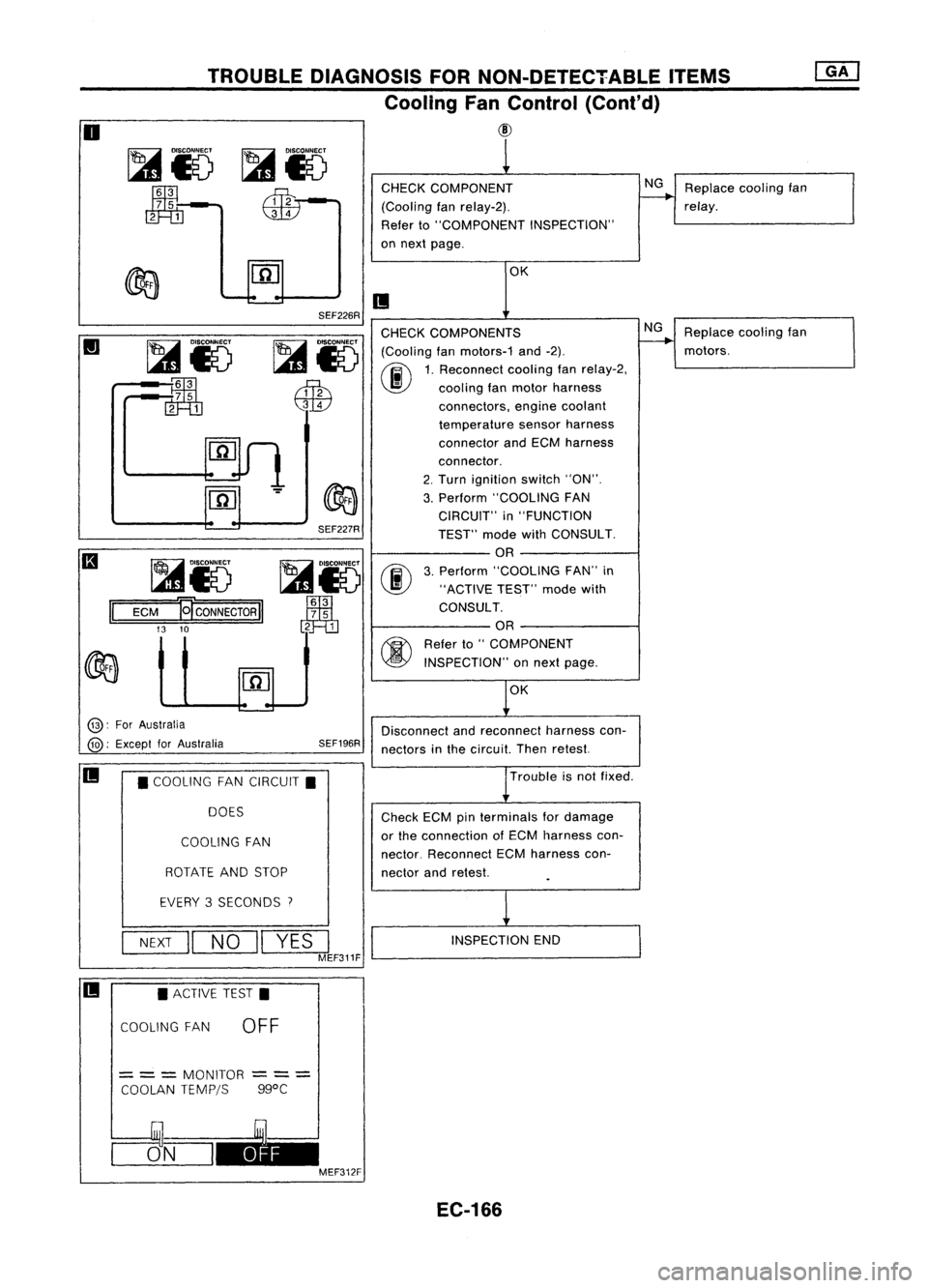
TROUBLEDIAGNOSIS FORNON-DETECTABLE ITEMS
Cooling FanControl (Cont'd)
@
o
~i5
~-
m=m
CHECK
COMPONENT
(Cooling fanrelay-2).
Refer to"COMPONENT INSPECTION"
on next page.
NG
Replace coolingfan
relay.
OK
II
Replacecoolingfan
motors.
NG
OK
SEF226R
SEF227R
~i5
00
Jm1
3
7 5
2 1
CHECK
COMPONENTS
~ IDlsco~
(Coolingfanmotors-1 and-2).
I...s1
0~
1.Rec~nnect coolingfanrelay-2,
~ \J!}
coolingfanmotor harness
QW
connectors,enginecoolant
temperature sensorharness
connector andECM harness
connector.
2. Turn ignition switch"ON".
3. Perform "COOLING FAN
CIRCUIT" in"FUNCTION
TEST" modewithCONSULT.
OR
3. Perform "COOLING FAN"in
"ACTIVE TEST"modewith
CONSULT.
OR
~ Referto"COMPONENT
~ INSPECTION" onnext page.
~i5
:~
rn=m
~i5
ECM
El'CONNECTORII
13 10
II
@:
ForAustralia
@:
Except forAustralia SEF196R
Disconnect
andreconnect harnesscon-
nectors inthe circuit. Thenretest.
II
•COOLING FANCIRCUIT.
DOES
COOLING FAN
ROTATE ANDSTOP
Trouble
isnot fixed .
Check ECMpinterminals fordamage
or the connection ofECM harness con-
nector. Reconnect ECMharness con-
nector andretest.
EVERY 3SECONDS
7
NEXT
II
NO
II
YES
I
MEF311F
INSPECTION
END
II •
ACTIVE TEST.
COOLING FAN
OFF
=
= =
MONITOR
COOLAN TEMPjS
---
---
ggoC
CJ5_N_I~ MEF312F
EC-166
Page 898 of 1701
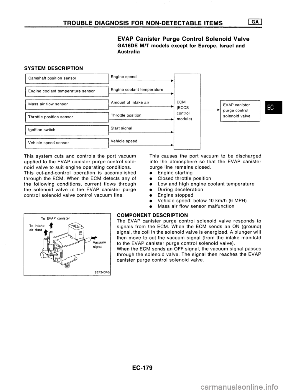
TROUBLEDIAGNOSIS FORNON-DETECTABLE ITEMS
EVAP Canister PurgeControl Solenoid Valve
GA16DE MITmodels exceptforEurope, Israeland
Australia
SYSTEM DESCRIPTION
Camshaft positionsensor
Engine coolant temperature sensor
Mass airflow sensor
Throttle positionsensor
Ignition switch
Vehicle speedsensor Engine
speed
Engine coolant temperature
Amount ofintake air
Throttle position
Start signal
Vehicle speed ECM
(ECCS
control
module) EVAP
canister
purge control
solenoid valve
•
This system cutsandcontrols theport vacuum
applied tothe EVAP canister purgecontrol sole-
noid valve tosuit engine operating conditions.
This cut-and-control operationisaccomplished
through theECM. When theECM detects anyof
the following conditions, currentflowsthrough
the solenoid valveinthe EVAP canister purge
control solenoid valvecontrol vacuum line. This
causes theport vacuum tobe discharged
into theatmosphere sothat theEVAP canister
purge lineremains closed.
• Engine starting
• Closed throttle position
• Low andhigh engine coolant temperature
• During deceleration
• Engine stopped
• Vehicle speed:below10km/h (6MPH)
• Mass airflow sensor malfunction
W>
Vacuum
signal
SEF240PG COMPONENT
DESCRIPTION
The EVAP canister purgecontrol solenoid valveresponds to
signals fromtheECM. When theECM sends anON (ground)
signal, thecoil inthe solenoid valveisenergized. Aplunger will
then move tocut the vacuum signal(fromtheintake manifc,ld
to the EVAP canister purgecontrol solenoid valve).
When theECM sends anOFF signal, thevacuum signalpasses
through thesolenoid valve.Thesignal thenreaches theEVAP
canister purgecontrol solenoid valve.
EC-179