sensor NISSAN ALMERA N15 1995 Service Manual
[x] Cancel search | Manufacturer: NISSAN, Model Year: 1995, Model line: ALMERA N15, Model: NISSAN ALMERA N15 1995Pages: 1701, PDF Size: 82.27 MB
Page 917 of 1701
TROUBLEDIAGNOSIS FORNON-DETECTABLE ITEMS
Valve Timing Control (VTC)
SYSTEM DESCRIPTION
Mass airflow sensor Amount
ofintake air
Camshaft positionsensor Enginespeed
Engine coolant temperature sensorEnginecoolant temperature ECM
(ECCS
control module) Valve
timing
control solenoid
valve
Throttle positionsensor Throttle
position
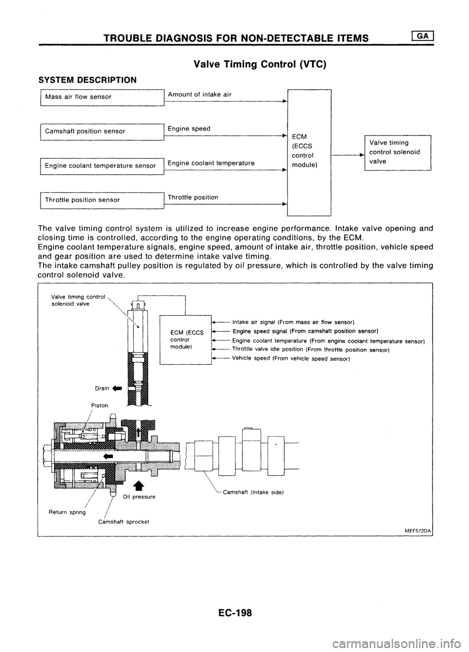
The valve timing control system isutilized toincrease engineperformance. Intakevalveopening and
closing timeiscontrolled, accordingtothe engine operating conditions, bythe ECM.
Engine coolant temperature signals,enginespeed,amount ofintake air,throttle position, vehiclespeed
and gear position areused todetermine intakevalvetiming.
The intake camshaft pulleyposition isregulated byoil pressure, whichiscontrolled bythe valve timing
control solenoid valve.
Drain .. Intake
airsignal (From massairflow sensor)
Engine speedsignal(From camshaft positionsensor)
Engine coolant temperature (Fromengine coolant temperature sensor)
Throttle valveidleposition (Fromthrottle position sensor)
Vehicle speed(Fromvehicle speedsensor)
"'- Camshaft (Intakeside)
EGM
(EGGS
control
module)
/
Camshaft sprocket
Piston
Valve
timing control ~
»
'o'""oid ,,',"
Ii
/
Return spring
MEF572DA
EC-198
Page 940 of 1701
TROUBLEDIAGNOSIS FORNON-DETECTABLE ITEMS~
Torque Converter ClutchSolenoid Valve(Cont'd)
SYSTEM DESCRIPTION
Throttle position sensor Throttle
valveopening angle
Engine coolant temperature sensorEnginecoolant temperature ECM
(ECCS
control
module) Torque
converter
clutch solenoid
valve
Vehicle speedsensor Vehicle
speed
The
AfT
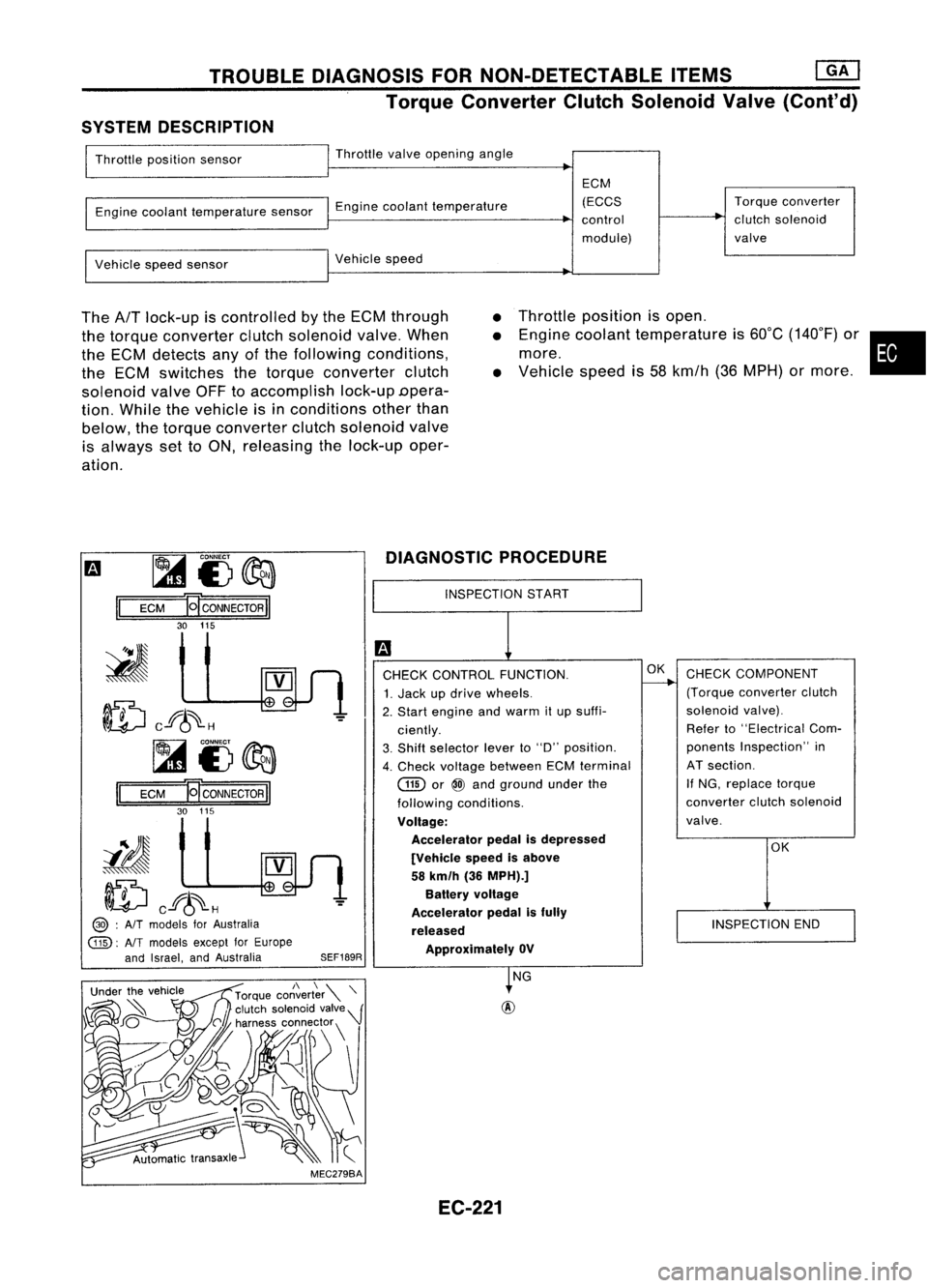
lock-up iscontrolled bythe ECM through
the torque converter clutchsolenoid valve.When
the ECM detects anyofthe following conditions,
the ECM switches thetorque converter clutch
solenoid valveOFFtoaccomplish lock-upDpera-
tion. While thevehicle isin conditions otherthan
below, thetorque converter clutchsolenoid valve
is always settoON, releasing thelock-up oper-
ation.
•
•
•
Throttle
position isopen .
Engine coolant temperature is60°C (140°F) or•
more.
Vehicle speedis58 kmfh (36MPH) ormore .
m ~
i3~
II
ECM
HCONNECTORII
30 115
ID
cf6~H
~i3~
II
ECM E
CONNECTOR
II
30 115
iIJ
ID
cf6~H
@> :
AIT
models forAustralia
@:
AlTmodels exceptforEurope
and Israel, andAustralia
SEF189RDIAGNOSTIC
PROCEDURE
INSPECTION START
CHECK CONTROL FUNCTION.
1. Jack updrive wheels.
2. Start engine andwarm itup suffi-
ciently.
3. Shift selector leverto"D" position.
4. Check voltage between ECMterminal
GID
or
@
and ground underthe
following conditions.
Voltage: Accelerator pedalisdepressed
[Vehicle speedisabove
58 km/h (36MPH).]
Battery voltage
Accelerator pedalisfully
released ApprOXimately OV
OK
CHECK COMPONENT
(Torque converter clutch
solenoid valve).
Refer to"Electrical Com-
ponents Inspection" in
AT section.
If NG, replace torque
converter clutchsolenoid
valve.
OK
INSPECTION END
MEC279BA NG
EC-221
Page 947 of 1701
ENGINEANDEMISSION CONTROLOVERALLSYSTEM
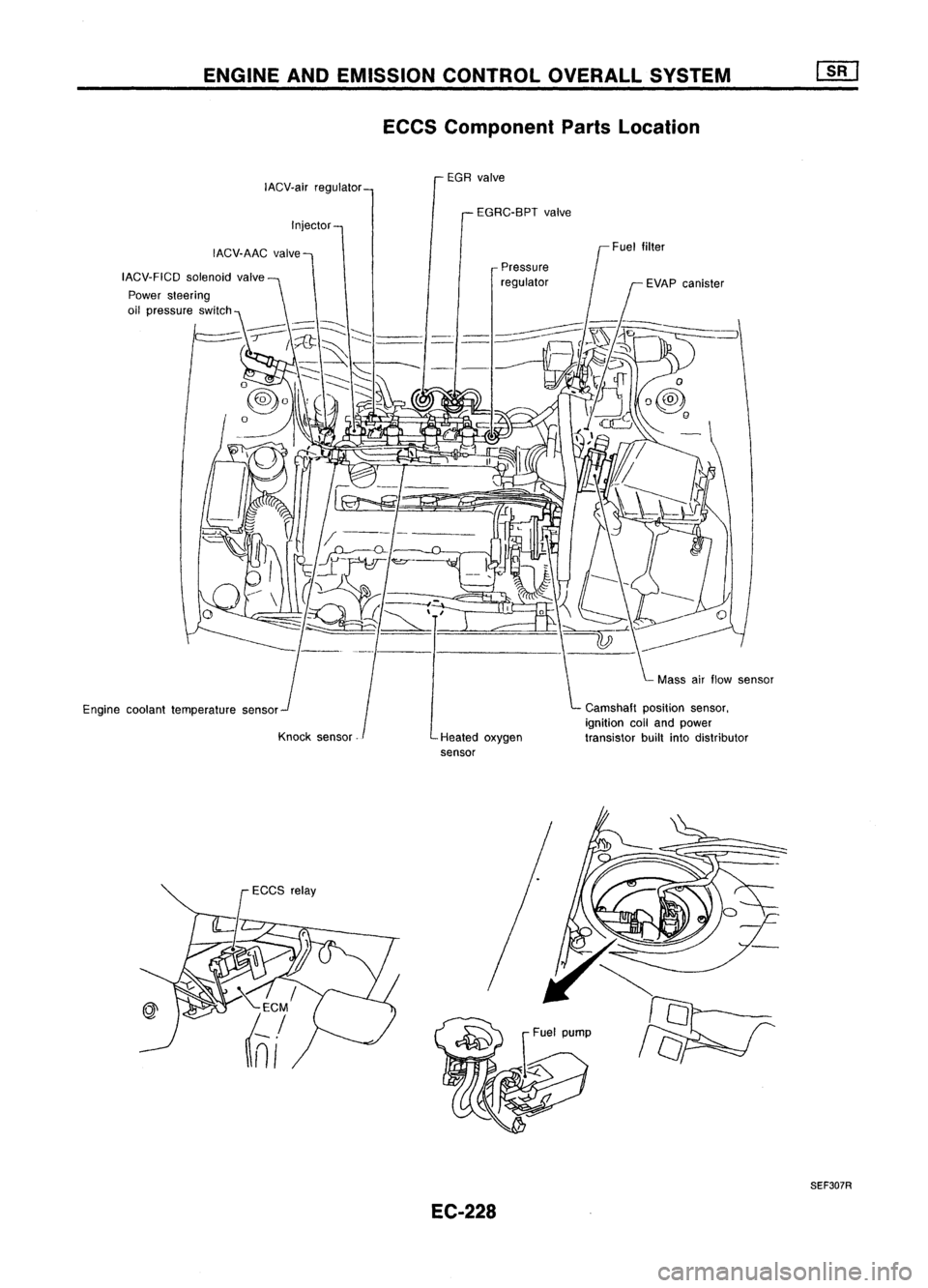
ECCS Component PartsLocation
EGR valve
IACV.air regulator
EGRC-BPTvalve
Injector
IACV.AAC valve
IACV.FICD solenoidvalve
Engine coolant temperature sensor
Knock sensor Pressure
regulator
Heated oxygen
sensor Camshaft
positionsensor,
ignition coiland power
transistor builtintodistributor
EC-228
SEF307R
Page 948 of 1701
ENGINEANDEMISSION CONTROL OVERALLSYSTEM ~
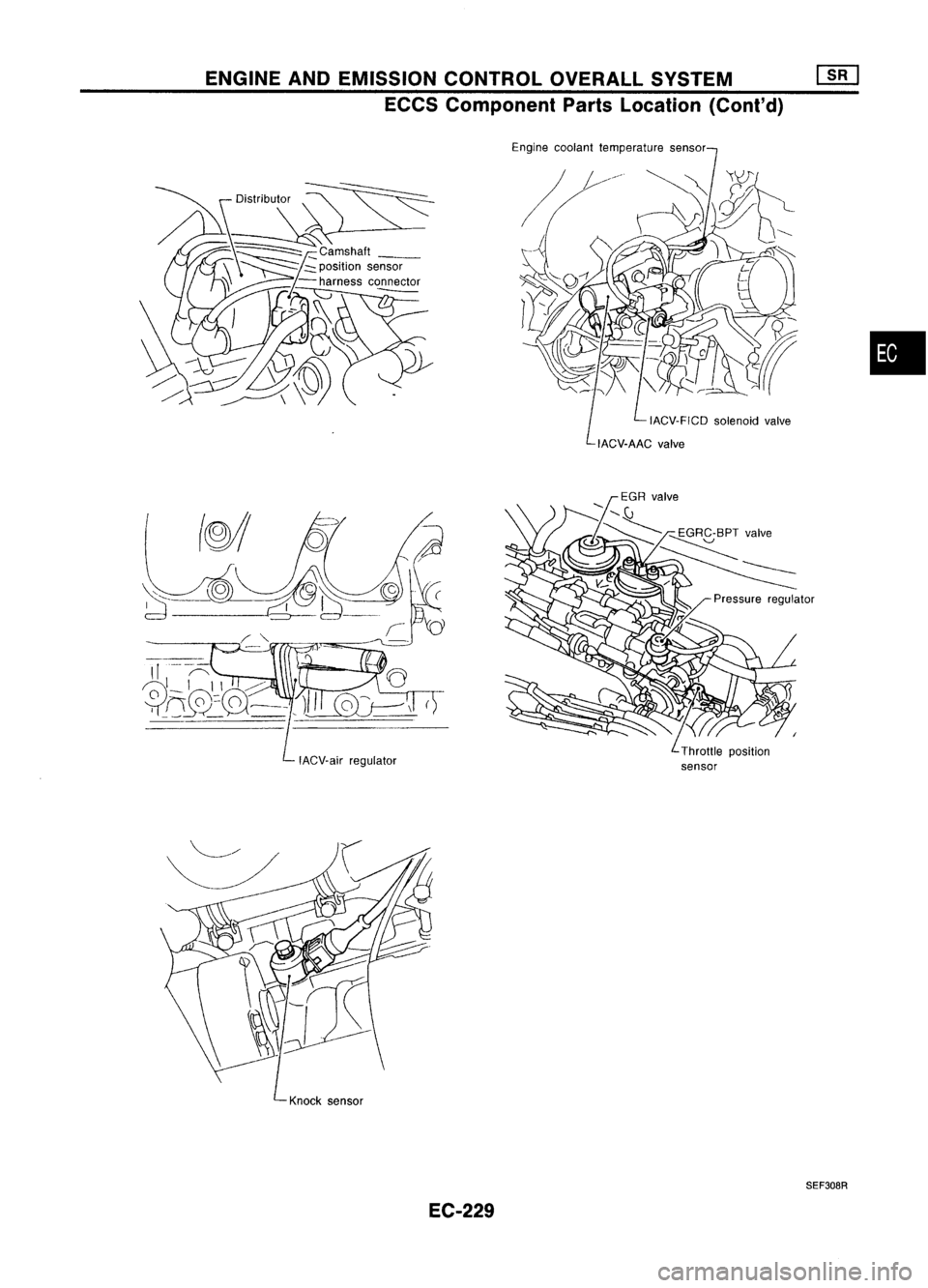
ECCS Component PartsLocation (Cont'd)
Engine coolant temperature sensor
IACV.FICD solenoidvalve
•
IACV.air regulator
Knock sensor
SEF308R
EC-229
Page 949 of 1701
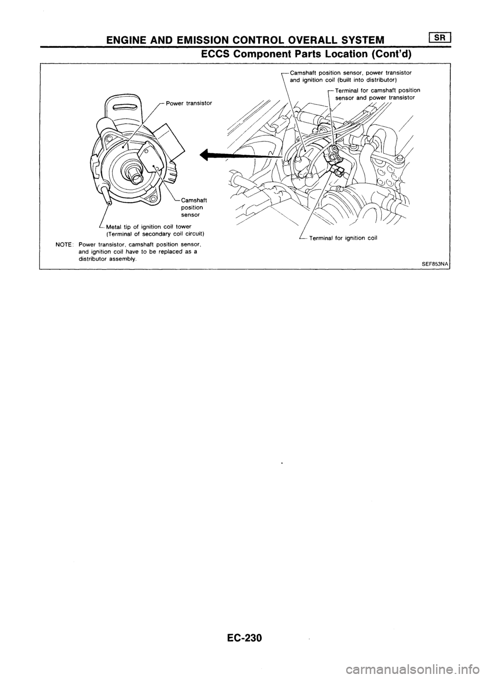
ENGINEANDEMISSION CONTROLOVERALLSYSTEM
ECCS Component PartsLocation (Cont'd)
Camshaft
L
position
sensor
Metal tipofignition coiltower
(Terminal ofsecondary coilcircuit)
NOTE: Powertransistor, camshaftpositionsensor,
and ignition coilhave tobe replaced asa
distributor assembly.
EC-230
Terminal
forignition coil
SEF853NA
Page 951 of 1701
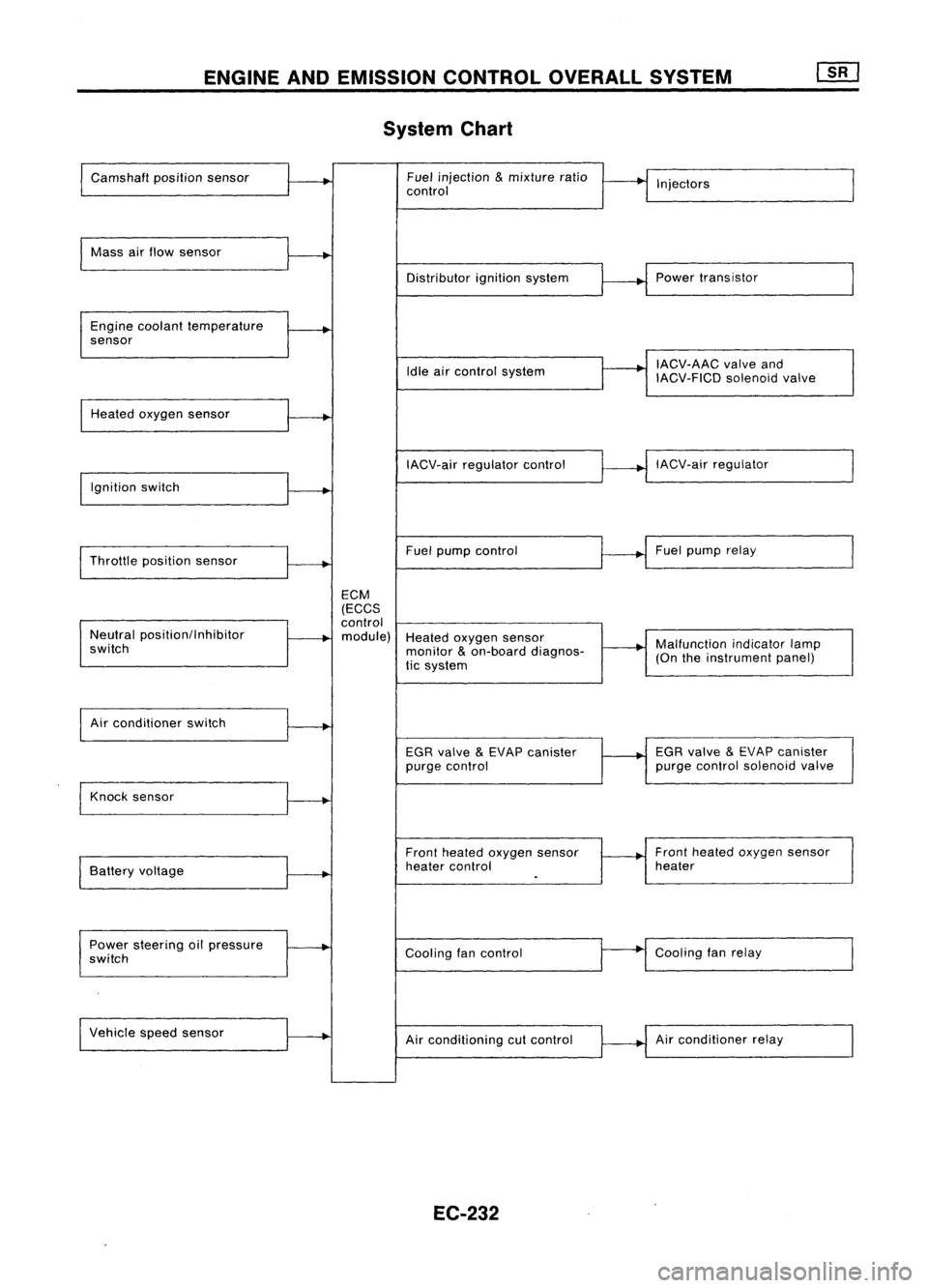
ENGINEANDEMISSION CONTROLOVERALLSYSTEM
System Chart
Camshaft positionsensor Fuel
injection
&
mixture ratio
•
I
I
control Injectors
Mass airflow sensor
I
Distributorignitionsystem
r
~1
Power transistor
Engine coolant temperature
.
sensor
I
IACV-AAC valveand
Idle aircontrol system
IACV-FICDsolenoidvalve
Heated oxygen sensor
I
IACV-airregulator control
~--..j
IACV-air regulator
I
Ignition switch
I
I
Throttle position sensor
~-+
Fuel
pump control Fuel
pump relay
ECM
(ECCS
control
Neutral position/Inhibitor
.
module) Heatedoxygen sensor
switch monitor
&
on-board diagnos-
~-+
Malfunction
indicatorlamp
tic system (On
theinstrument panel)
I
Air conditioner switch
t~
EGRvalve
&
EVAP canister
1---+
EGR
valve
&
EVAP canister
purge control purge
control solenoid valve
Knock sensor
.....
Frontheated oxygen sensor Front
heated oxygen sensor
Battery voltage
.
heater
control heater
I
.
Power steering oilpressure
~
Coolingfancontrol
--
Cooling
fanrelay
switch
Vehicle speedsensor
.....
Airconditioning cutcontrol Air
conditioner relay
EC-232
Page 952 of 1701
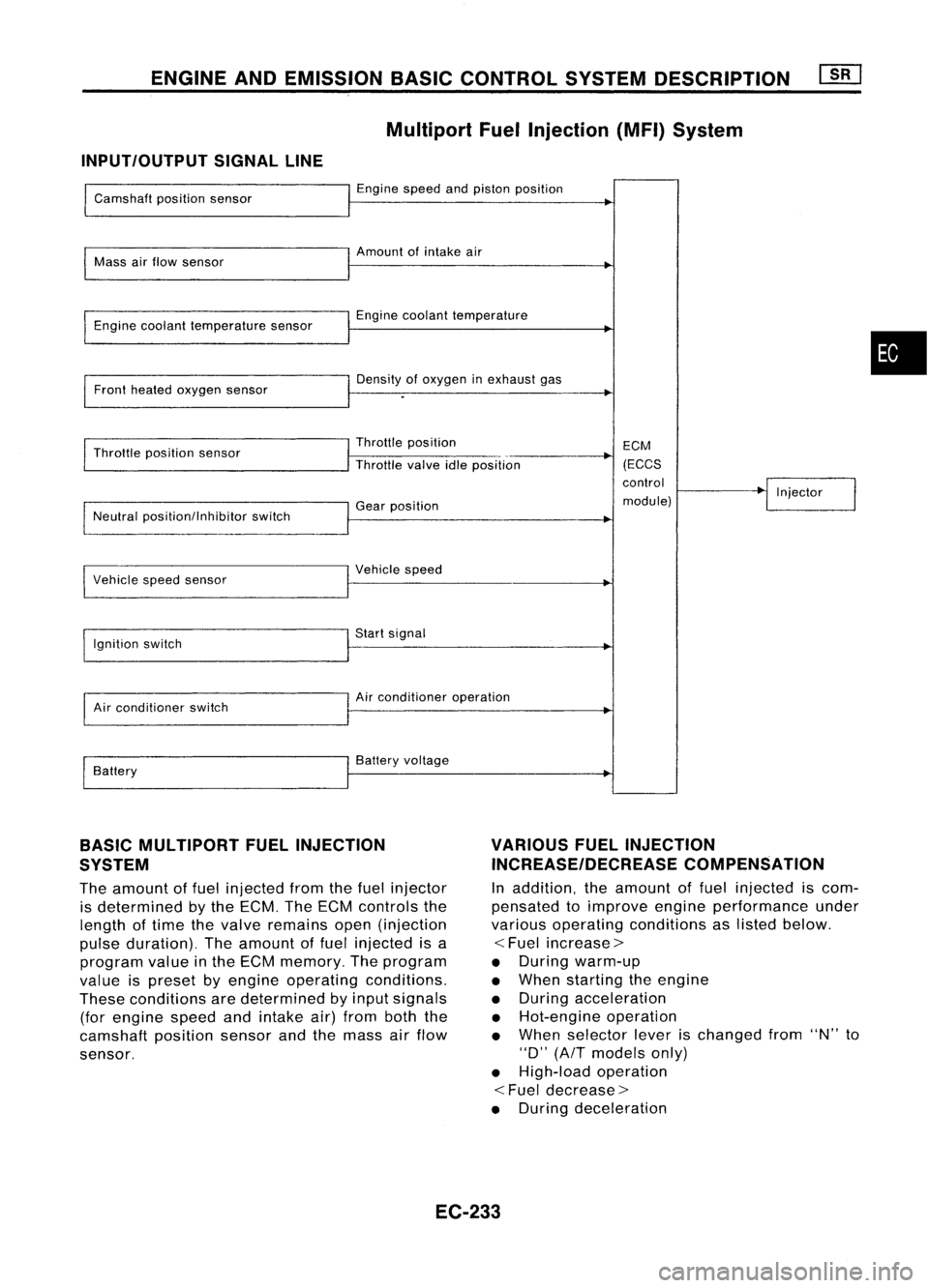
ENGINEANDEMISSION BASICCONTROL SYSTEMDESCRIPTION
Multiport FuelInjection (MFI)System
INPUT/OUTPUT SIGNALLINE
Camshaft positionsensor
Mass airflow sensor
Engine coolant temperature sensor
Front heated oxygen sensor
Throttle position sensor
Neutral position/lnhibitor switch
I
Vehicle speedsensor
Ignition switch
Air conditioner switch
Battery Engine
speedandpiston position
Amount ofintake air
Engine coolant temperature
Density ofoxygen inexhaust gas
Throttle position
Throttle valveidleposition
Gear position
I
Vehicle speed
Start signal
Air conditioner operation
Battery voltage ECM
(ECCS
control
module) Injector
•
BASIC MULTIPORT FUELINJECTION
SYSTEM
The amount offuel injected fromthefuel injector
is determined bythe ECM. TheECM controls the
length oftime thevalve remains open(injection
pulse duration). Theamount offuel injected isa
program valueinthe ECM memory. Theprogram
value ispreset byengine operating conditions.
These conditions aredetermined byinput signals
(for engine speedandintake air)from boththe
camshaft positionsensorandthemass airflow
sensor.
VARIOUS
FUELINJECTION
INCREASE/DECREASE COMPENSATION
In addition, theamount offuel injected iscom-
pensated toimprove engineperformance under
various operating conditions aslisted below.
<
Fuel increase>
• During warm-up
• When starting theengine
• During acceleration
• Hot-engine operation
• When selector leverischanged from"N"to
"0" (AfT models only)
• High-load operation
<
Fuel decrease>
• During deceleration
EC-233
Page 953 of 1701
![NISSAN ALMERA N15 1995 Service Manual ENGINEANDEMISSION BASICCONTROL SYSTEMDESCRIPTION [][]
Multiport FuelInjection (MFI)System (Cont'd)
CLOSED LOOP MIXTURERATIOFEEDBACK CONTROL(CLOSEDLOOP
CONTROL CONTROL)
The mixture ratiofeedback s NISSAN ALMERA N15 1995 Service Manual ENGINEANDEMISSION BASICCONTROL SYSTEMDESCRIPTION [][]
Multiport FuelInjection (MFI)System (Cont'd)
CLOSED LOOP MIXTURERATIOFEEDBACK CONTROL(CLOSEDLOOP
CONTROL CONTROL)
The mixture ratiofeedback s](/img/5/57349/w960_57349-952.png)
ENGINEANDEMISSION BASICCONTROL SYSTEMDESCRIPTION [][]
Multiport FuelInjection (MFI)System (Cont'd)
CLOSED LOOP MIXTURERATIOFEEDBACK CONTROL(CLOSEDLOOP
CONTROL CONTROL)
The mixture ratiofeedback systemprovides thebest air-fuel
Feedback signal
mixtureratiofordriveability andemission control.Thethree
way catalyst canthen better reduce CO,HCand NOx emissions.
This system usesaheated oxygen sensorinthe exhaust man-
ifold tomonitor ifthe engine operation isrich orlean. TheECM
adjusts theinjection pulsewidthaccording tothe sensor volt-
age signal. Formore information abouttheheated oxygen
sensor, refertoEC-362. Thismaintains themixture ratiowithin
MEF025DD
therange ofstoichiometric (idealair-fuel mixture).
This stage isreferred toas the closed loopcontrol condition.
OPEN LOOPCONTROL
The open loopsystem condition referstowhen theECM detects
any ofthe following conditions. Feedbackcontrolstopsinorder
to maintain stabilized fuelcombustion.
• Deceleration andacceleration
• High-load, high-speed operation
• Engine idling
• Malfunction ofheated oxygen sensororits circuit
• Insufficient activationofheated oxygen sensoratlow
engine coolant temperature
• High-engine coolanttemperature
• After shifting from"N"to"0"
• During warm-up
• When starting theengine
MIXTURE RATIOSELF-LEARNING CONTROL
The mixture ratiofeedback controlsystem monitors themixture
ratio signal transmitted fromtheheated oxygen sensor. This
feedback signalisthen senttothe ECM. TheECM controls the
basic mixture ratioasclose tothe theoretical mixtureratioas
possible. However, thebasic mixture ratioisnot necessarily con-
trolled asoriginally designed. Bothmanufacturing differences
(Le., mass airflow sensor hotwire) andcharacteristic changes
during operation (Le.,injector clogging) directlyaffectmixture
ratio.
Accordingly, thedifference betweenthebasic andtheoretical
mixture ratiosismonitored inthis system. Thisisthen com-
puted interms of"injection pulseduration" toautomatically
compensate forthe difference betweenthetwo ratios.
EC-234
Page 954 of 1701
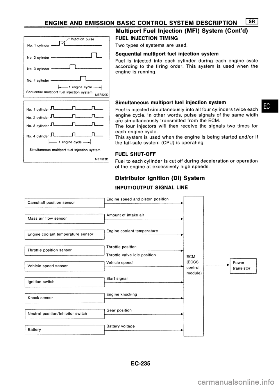
Twotypes ofsystems areused.
Sequential multiportfuelinjection system
Fuel isinjected intoeach cylinder duringeachengine cycle
according tothe firing order. Thissystem isused when the
engine isrunning.
ENGINE
ANDEMISSION BASICCONTROL SYSTEMDESCRIPTION ~
Multiport FuelInjection (MFI)System (Cont'd)
FUEL INJECTION TIMING
..--./ Injection pulse
NO.1 cylinder
---1
0/1 _
NO.3 cylinder
~n~ _
No.2
cylinder
rL
NO.4 cylinder
~n~_
~ 1engine cycle
----j
Sequential multiportfuelinjection system
MEF522D
No. 1cylinder
jl
n
rL-
No. 2cylinder
jl
n
rL-
No. 3cylinder
]l
n
rL-
NO.4 cylinder
D
n
fL-.
~- 1engine cycle
---1
Simultaneous multiportfuelinjection system
MEF523D Simultaneous
multipartfuelinjection system
Fuel isinjected simultaneously intoallfour cylinders twiceeach
engine cycle.Inother words, pulsesignals ofthe same width
are simultaneously transmittedfromtheECM.
The four injectors willthen receive thesignals twotimes for
each engine cycle.
This system isused when theengine isbeing started and/orif
the fail-safe system(CPU)isoperating.
FUEL SHUT-OFF
Fuel toeach cylinder iscut offduring deceleration oroperation
of the engine atexcessively highspeeds.
•
Distributor Ignition(DI)System
INPUT/OUTPUT SIGNALLINE
Camshaft positionsensor Engine
speedandpiston position
Mass airflow sensor Amount
ofintake air
Engine coolant temperature sensor Engine
coolant temperature
Throttle position sensor
I
Vehicle speedsensor Throttle
position
Throttle valveidleposition
I
Vehicle speed ECM
(ECCS
control module) Power
transistor
Ignition switch Start
signal
Knock sensor Engine
knocking
Neutral position/Inhibitor switchGear
position
Battery Battery
voltage
EC-235
Page 955 of 1701
A
N
600 1,000 1,4001,8002,200
Engine speed(rpm) SEF742M
Tp
(msec)
1.75
~ 1.50
.~
3l
1.25
:;
a.
c:
1.00
.Q
~ 0.75
E ENGINE
ANDEMISSION BASICCONTROL SYSTEMDESCRIPTION
Distributor Ignition(01)System (Cont'd)
SYSTEM DESCRIPTION
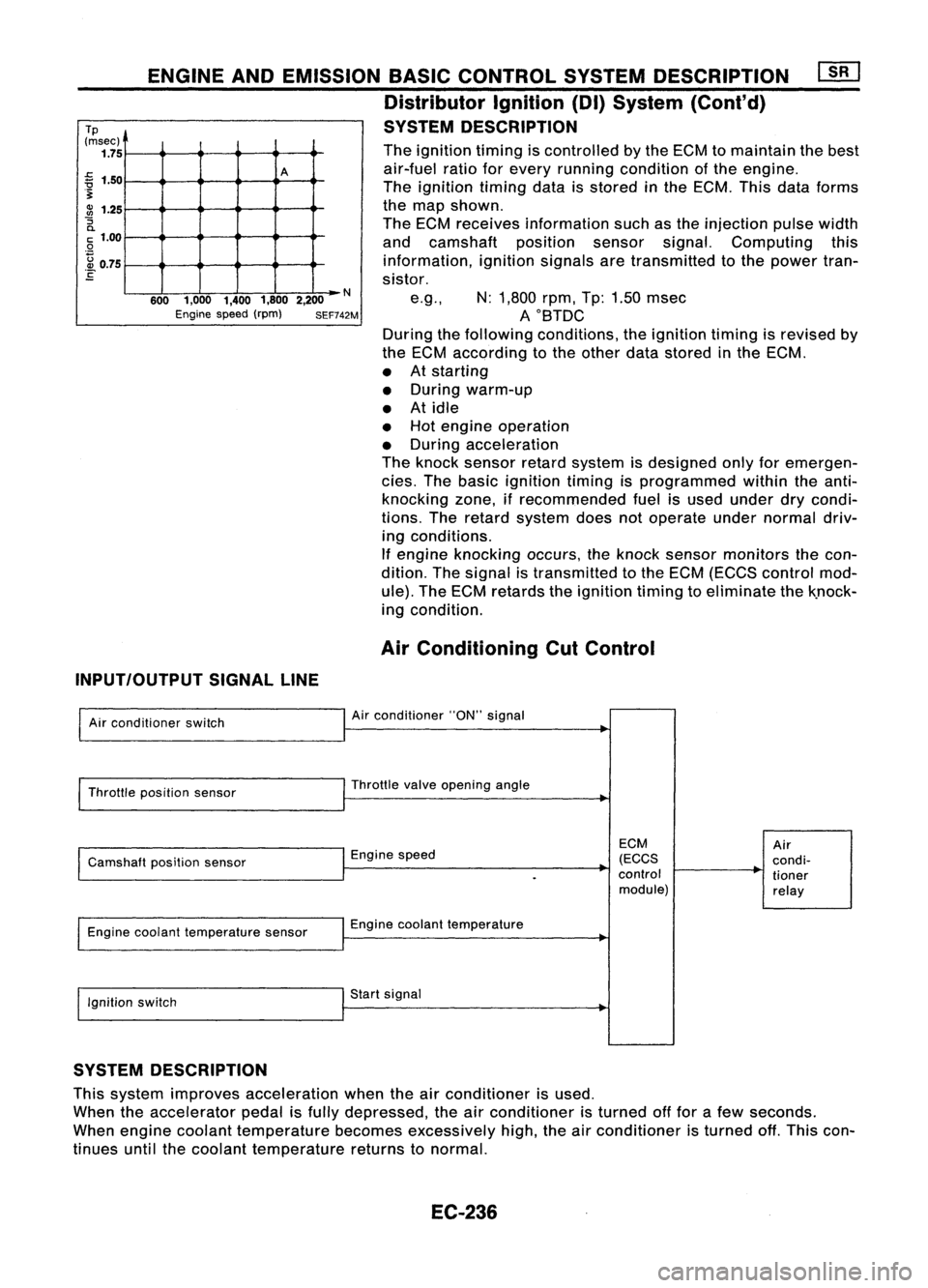
The ignition timingiscontrolled bythe ECM tomaintain thebest
air-fuel ratioforevery running condition ofthe engine.
The ignition timingdataisstored inthe ECM. Thisdataforms
the map shown.
The ECM receives information suchasthe injection pulsewidth
and camshaft positionsensorsignal.Computing this
information, ignitionsignalsaretransmitted tothe power tran-
sistor.
e.g., N:1,800 rpm,Tp:1.50 msec
AOBTDC
During thefollowing conditions, theignition timingisrevised by
the ECM according tothe other datastored inthe ECM.
• Atstarting
• During warm-up
• Atidle
• Hot engine operation
• During acceleration
The knock sensor retardsystem isdesigned onlyforemergen-
cies. Thebasic ignition timingisprogrammed withintheanti-
knocking zone,ifrecommended fuelisused under drycondi-
tions. Theretard system doesnotoperate undernormal driv-
ing conditions.
If engine knocking occurs,theknock sensor monitors thecon-
dition. Thesignal istransmitted tothe ECM (ECCS control mod-
ule). TheECM retards theignition timingtoeliminate thek.nock-
ing condition.
Air Conditioning CutControl
INPUT/OUTPUT SIGNALLINE
Air conditioner switch
Throttle position sensor
Camshaft positionsensor
Engine coolant temperature sensor
Ignition switch Air
conditioner "ON"signal
Throttle valveopening angle
Engine speed
Engine coolant temperature
Start signal
ECM
(ECCS
control module)
Air
condi-
tioner
relay
SYSTEM DESCRIPTION
This system improves acceleration whentheairconditioner isused.
When theaccelerator pedalisfully depressed, theairconditioner isturned offfor afew seconds.
When engine coolant temperature becomesexcessively high,theairconditioner isturned off.This con-
tinues untilthecoolant temperature returnstonormal.
EC-236