sensor NISSAN ALMERA N15 1995 Service Manual
[x] Cancel search | Manufacturer: NISSAN, Model Year: 1995, Model line: ALMERA N15, Model: NISSAN ALMERA N15 1995Pages: 1701, PDF Size: 82.27 MB
Page 1016 of 1701
 (32) (68)(104)(140)(176)(212)
Temperature 'C
(OF)
SEF594K
SEF012P Engine
Coolan")
TROUBLEDIAGNOSIS FOROTC13
20
19
6
9
4
~ 2
~ 1.0
1ij
0.8
'w
8!
04
0.2
0.1
.20 020 40 6080100
(-4) (32) (68)(104)(140)(176)(212)
Temperature 'C
(OF)
SEF594K
SEF012P Engine
Coolant Temperature Sensor(ECTS)
The engine coolant temperature sensorisused todetect the
engine coolant temperature. Thesensor modifies avoltage sig-
nal from theECM. Themodified signalreturns tothe ECM as
the engine coolant temperature input.Thesensor usesather-
mistor whichissensitive tothe change intemperature. The
electrical resistance ofthe thermistor decreases astempera-
ture increases.
<
Reference data>
Engine coolant temper-
Voltage Resistance
ature
.
(V)(kQ)
'C ("F)
-10 (14) 4.4
7.0-11.4
20 (68) 3.5
2.1-2.9
50 (122) 2.20.68-1.00
90 (194) 0.9
0.236-0.260
•
Diagnostic
Trouble Code
No. Malfunction
isdetected when... Check
Items
(Possible Cause)
13 •
An excessively highorlow voltage fromthesensor •Harness orconnectors
is sent toECM. (Thesensor circuitisopen orshorted.)
• Engine coolant temperature sensor
DIAGNOSTIC TROUBLECODECONFIRMATION
PROCEDURE
rF.i\
1)Turn ignition switch"ON".
~ 2)Select "DATA MONITOR" modewithCONSULT.
3) Wait atleast 5seconds.
---------- OR----------
rm
1)Turn ignition switch"ON"andwait atleast 5seconds.
~ 2)Turn ignition switch"OFF", waitatleast 7seconds
and then turn"ON".
3) Perform "Diagnostic TestMode II"(Self-diagnostic
results) withECM.
EC-297
Page 1017 of 1701
![NISSAN ALMERA N15 1995 Service Manual TROUBLEDIAGNOSIS FORDTC13 ~
Engine Coolant Temperature Sensor(ECTS)
(Cont'd)
EC-ECTS-01
~ENGlNE COOLANT
TEMPERATURE
SENSOR
@lID
Il:j.JJ
4=U
BR/Y B
I I
BR/Y ~ B
$--1--$
BR/Y
U])
B _.
D](/img/5/57349/w960_57349-1016.png "NISSAN ALMERA N15 1995 Service Manual TROUBLEDIAGNOSIS FORDTC13 ~
Engine Coolant Temperature Sensor(ECTS)
(Cont'd)
EC-ECTS-01
~ENGlNE COOLANT
TEMPERATURE
SENSOR
@lID
Il:j.JJ
4=U
BR/Y B
I I
BR/Y ~ B
$--1--$
BR/Y
U])
B _.
D")
TROUBLEDIAGNOSIS FORDTC13 ~
Engine Coolant Temperature Sensor(ECTS)
(Cont'd)
EC-ECTS-01
~ENGlNE COOLANT
TEMPERATURE
SENSOR
@lID
Il:j.JJ
4=U
BR/Y B
I I
BR/Y ~ B
$--1--$
BR/Y
U])
B _.
Detectable line
for DTC
-: Non-detectable
line forDTC
~~
@
L
~
~ GY
•
t
BR/Y
B
B
Ii1'sH
~
12-91
TW GND
GND
ECM
-A -A
(ECCS
CONTROL
MODULE)
em
em
L
EC-298 HEC005
Page 1018 of 1701

If NG, repair harness or
connectors.
Replace enginecoolant
tempe")
•
Check
thefollowing.
• Harness foropen or
short between ECM
and engine coolant
temperature sensor
• Harness connectors
@D,@)
If NG, repair harness or
connectors.
Replace enginecoolant
temperature sensor.
Check
thefollowing.
• Harness foropen or
short between ECM
and engine coolant
temperature sensor
• Harness connectors
@D.@)
If NG. repair harness or
connectors.
NG
NG
OK
CHECK COMPONENT
(Engine coolanttemperature sensor).
Refer to"COMPONENT INSPECTION"
on next page.
CHECK
GROUND CIRCUIT.
1. Turn ignition switch"OFF".
2. Check harness continuity between
terminal
CD
and engine ground.
Continuity shouldexist.
If OK, check harness forshort.
INSPECTION
START
OK
m
CHECK POWER SUPPLY.
1. Turn ignition switch"OFF".
2. Disconnect enginecoolant tempera-
ture sensor harness connector.
3. Turn ignition switch"ON".
4. Check voltage between terminal
@
and ground withCONSULT ortester.
Voltage: . Approximately 5V
SEF518Q
SEF519Q
MEC7188A
TROUBLE
DIAGNOSIS FORDTC13
mJ
Engine Coolant Temperature Sensor(ECTS)
(Cont'd)
DIAGNOSTIC PROCEDURE
~i5
~
~io
~
Disconnectandreconnect harnesscon-
nectors inthe circuits. Thenretest.
Trouble isnot fixed.
Check ECMpinterminals fordamage
and check theconnection ofECM har-
ness connector. ReconnectECMhar-
ness connector andretest.
INSPECTION END
EC-299
Page 1019 of 1701

(Cont'd)
COMPONENT INSPECTION
SEF152P Engine
coolant temperature sensor
Check resistance asshown inthe figure.
Temperature °C")
TROUBLEDIAGNOSIS FORDTC13 ~
Engine Coolant Temperature Sensor(ECTS)
(Cont'd)
COMPONENT INSPECTION
SEF152P Engine
coolant temperature sensor
Check resistance asshown inthe figure.
Temperature °C
(OF)
20 (68)
50 (122)
90 (194)
Resistance
kQ
2.1 -2.9
0.68 -1.00
0.236 -0.260
If NG, replace enginecoolant temperature sensor.
EC-300
Page 1020 of 1701

The ignition coilisasmall molded type.Theignition signalfrom
the ECM issent tot")
TROUBLEDIAGNOSIS FORDTC21
Ignition Signal
COMPONENT DESCRIPTION
Ignition coil
&
power transistor (Builtintodistributor)
The ignition coilisasmall molded type.Theignition signalfrom
the ECM issent tothe power transistor. Thepower transistor
switches onand offthe ignition coilprimary circuit.Asthe pri-
mary circuit isturned onand off,the proper highvoltage is
induced inthe coil secondary circuit.
Diagnostic Trouble
Code No.
21
Malfunction
isdetected when...
• The ignition signalinthe primary circuitisnot sent
to ECM during engine cranking orrunning. Check
Items
(Possible Cause)
• Harness orconnectors
(The ignition primary circuitisopen orshorted.)
• Power transistor unit.
• Resistor
• Camshaft positionsensor
• Camshaft positionsensorcircuit
•
DIAGNOSTIC TROUBLECODECONFIRMATION
PROCEDURE
Note: Ifboth DTC11and 21are displayed, performTROUBLE
DIAGNOSIS FORDTC11first. Refer toEC-289.
(F.I\ 1)Turn ignition switch"ON".
~ 2)Select "DATA MONITOR" modewithCONSULT.
3) Start engine. (Ifengine doesnotrun, turn ignition
switch to"START" foratleast 5seconds.)
---------- OR----------
~ 1)Turn ignition switch"ON".
~ 2)Start engine. (Ifengine doesnotrun, turn ignition
switch to"START" foratleast 5seconds.)
3) Turn ignition switch"OFF", waitatleast 7seconds
and then turn"ON".
4) Perform "Diagnostic TestMode II"(Self-diagnostic
results) withECM.
EC-301
Page 1024 of 1701
![NISSAN ALMERA N15 1995 Service Manual
•
Approximately
25kQ
Resistance
[at25'C (77'F)]
0.5 -1.0Q
Terminal
(J) -@
(Primary coil)
(J) -
@
(Secondary coil)
For checking secondary coil,remove distributor capand
measure resis](/img/5/57349/w960_57349-1023.png "NISSAN ALMERA N15 1995 Service Manual
•
Approximately
25kQ
Resistance
[at25'C (77'F)]
0.5 -1.0Q
Terminal
(J) -@
(Primary coil)
(J) -
@
(Secondary coil)
For checking secondary coil,remove distributor capand
measure resis")
•
Approximately
25kQ
Resistance
[at25'C (77'F)]
0.5 -1.0Q
Terminal
(J) -@
(Primary coil)
(J) -
@
(Secondary coil)
For checking secondary coil,remove distributor capand
measure resistance betweencoiltower metaltip
@
and
terminal
(f).
If NG, replace distributor assemblyasaunit.
Ignition
coil
1. Disconnect ignitioncoilharness connector.
2. Check resistance asshown inthe figure.
AEC902
MEC719B
TROUBLE
DIAGNOSIS FORDTC21
Ignition Signal(Cont'd)
COMPONENT INSPECTION
LCoiltower meta/tip
Powertransistor
1. Disconnect camshaftpositionsensor
&
power transistor
harness connector andignition coilharness connector.
2. Check power transistor resistance betweenterminals
CID
and
@.
Terminals Resistance
Result
NotOQ
OK
@
and
@
on
NG
If NG, replace distributor assembly.
Resistor
1. Disconnect resistorharness connector.
2. Check resistance betweenterminals
CD
and
CID
Resistance:
Approximately
2.2kQ
[at
25°C (77°F»
If NG, replace resistor.
EC-305
Page 1025 of 1701

The knock sensor isattached tothe cylinder block.Itsenses
engine knocking usingapiezoelectric element.Aknocking
vibr
ion
fromthecylinder blockissensed as")
TROUBLEDIAGNOSIS FORDTC34
Knock Sensor (KS)
The knock sensor isattached tothe cylinder block.Itsenses
engine knocking usingapiezoelectric element.Aknocking
vibr
ion
fromthecylinder blockissensed asvibrational pres-
sure. Thispressure is
converted
intoa
voltage
signalandsent
to the ECM.
PIEZO-ELEMENT SEF598K
Diagnostic
Trouble Code Malfunctionisdetected when....
No.
34 •An excessively loworhigh voltage fromtheknock
sensor issent toECM. Check
Items
(Possible Cause)
• Harness orconnectors
(The knock sensor circuitisopen orshorted.)
• Knock sensor
DIAGNOSTIC TROUBLECODECONFIRMATION
PROCEDURE
fiii\
1)Turn ignition switch"ON"andselect "DATA
\J!}
MONITOR" modewithCONSULT.
2) Start engine andrunitfor atleast 5seconds atidle
speed.
----------OR -----------
1) Start engine andrunitfor atleast 5seconds atidle
speed.
2) Turn ignition switch"OFF", waitatleast 7seconds
and then turn"ON".
3) Perform "Diagnostic TestMode II"(Self-diagnostic
results) withECM.
EC-306
Page 1026 of 1701
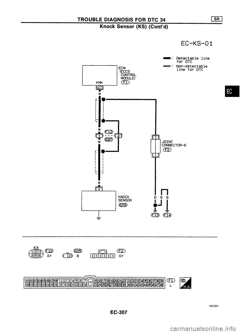
TROUBLEDIAGNOSIS FORDTC34
Knock Sensor (KS)(Cont'd)
EC-KS-01
rn
JOINT
CONNECTOR-6
@
1
ECM
(ECCS
CONTROL
MOOULE)
(IT)
KNK
1
2';
I
W
f .--------.
I I
I I
I I
I I
I I
I I
,,:"
.
w~
w
@Z)
f •
I I
I I
I I
I I
I I
I I
I:: )
-:
Detectable line
for DTC
-: Non-detectable
line forDTC
•
KNOCK
SENSOR
~
~m>
~GY
~@
I.IIIIIIII1lII
GY
em
L
HEC007
EC-307
Page 1027 of 1701

Repairharness orcon-
nectors.
Repair harness orcon-
nectors.
Replace knocksensor.
NG
~
INSPECTION
START
Loosen andretighten engineground
screws.
OK
Disconnect andreconnect harnesscon-
nectors inthe circuit. Thenretest.
OK
CHECK COMPONENT
(Knock sensor).
Refer to"COMPONENT INSPECTION"
below.
Troubleisnot fixed.
Check ECMpinterminals fordamage
and check theconnection ofECM har-
ness connector. ReconnectECMhar-
ness connector andretest,
OK
m
CHECK SUB.HARNESS CIRCUIT.
1. Disconnect knocksensor harness
connector.
2. Check harness continuity between
knock sensor harness connector ter-
minal
@
and knock sensor sub-har-
ness connector terminal
CD.
Continuity shouldexist.
If
OK, check harness forshorl.
fa
CHECK INPUTSIGNAL CIRCUIT.
1. Turn ignition switch"OFF".
2. Disconnect ECMharness connector
and knock sensor harness connector.
3. Disconnect sub-harness connectors
@,@D.
4. Check harness continuity between
terminal
CD
and ECM terminal
@.
Continuity shouldexist.
If OK, check harness forshorl.
MEC757B
MEC7568
TROUBLE
DIAGNOSIS FORDTC34
Knock Sensor (KS)(Cont'd)
DIAGNOSTIC PROCEDURE
~15
..
~
\ili:tV
~~
\tiiliJ
~15
ECM
BCONNECTORII
27
,,~n~(
r\r~\//\ \
AY
..("'~Inlake manifold
~
\
fa
II
INSPECTIONEND
COMPONENT INSPECTION
Knock sensor
• Use anohmmeter whichcanmeasure morethan10MO.
1. Disconnect knocksensor harness connector.
2. Check resistance betweenterminal
@
and ground.
Resistance: 500-620 kO[at25°C (77°F))
CAUTION:
Do not use any knock sensors thathave been dropped orphys-
ically damaged. Useonly newones.
AEC719
EC-308
Page 1028 of 1701

TROUBLEDIAGNOSIS FORDTC43
SEF089K Throttle
Position Sensor
The throttle position sensorresponds tothe accelerator pedal
movement. Thissensor isakind ofpotentiometer whichtrans-
forms thethrottle position intooutput voltage, andemits the
voltage signaltothe ECM. Inaddition, thesensor detects the
opening andclosing speedofthe throttle valveandfeeds the
voltage signaltothe ECM.
Idle position ofthe throttle valveisdetermined
by
the ECM
receiving thesignal fromthethrottle position sensor.Thisone
controls engineoperation suchasfuel cut.
•
SEF520Q
VI
Supplyvoltage:
~ 4.55V (Applied be~VoIee~_terminals NO.1and3)
.~
2
[f~.. ~
L
L
1
&c
~ ~M
Throttle position sensor g
-g
:; ~ 0.5
0.
8 ~
00 -~---_. 90
Throttle valveopening angle(deg.)
Diagnostic Trouble
Code No. Malfunction
isdetected when... Check
Items
(Possible Cause)
43
•
An excessively loworhigh voltage fromthesensor •Harness orconnectors
is sent toECM. (Thesensor circuitisopen orshorted.)
• Throttle position sensor
EC-309