sensor NISSAN ALMERA N15 1995 Service Manual
[x] Cancel search | Manufacturer: NISSAN, Model Year: 1995, Model line: ALMERA N15, Model: NISSAN ALMERA N15 1995Pages: 1701, PDF Size: 82.27 MB
Page 1029 of 1701
TROUBLEDIAGNOSIS FORDTC43
Throttle Position Sensor(Cont'd)
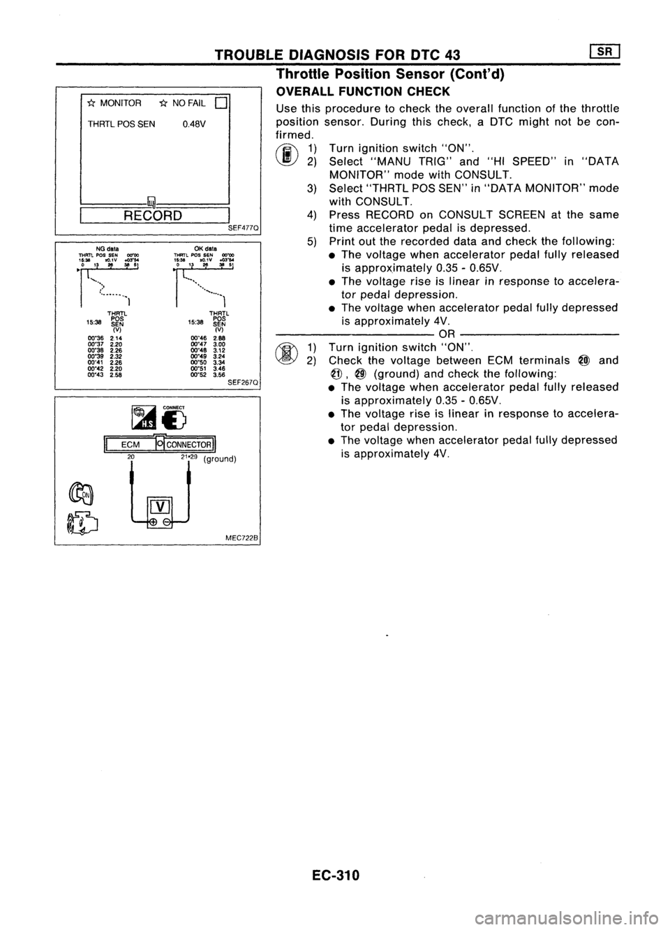
OVERALL FUNCTION CHECK
"*
MONITOR *NO FAIL
0
THRTL
pas
SEN 0.48V
I- I~-----..l
~-R-E-CO-R-D-~I
SEF477QUse
thisprocedure tocheck theoverall function ofthe throttle
position sensor.Duringthischeck, aDTC might notbecon-
firmed.
rij\
1)
~ 2)
Turn
ignition switch"ON".
Select "MANU TRIG"and"HISPEED" in"DATA
MONITOR" modewithCONSULT.
3) Select "THRTL POSSEN" in"DATA MONITOR" mode
with CONSULT.
4) Press RECORD onCONSULT SCREENatthe same
time accelerator pedalisdepressed.
5) Print outthe recorded dataandcheck thefollowing:
• The voltage whenaccelerator pedalfullyreleased
is approximately 0.35-0.65V .
• The voltage riseislinear inresponse toaccelera-
tor pedal depression .
• The voltage whenaccelerator pedalfullydepressed
is approximately 4V.
---------- OR----------
1) Turn ignition switch"ON",
2) Check thevoltage between ECMterminals
@J
and
@,
@
(ground) andcheck thefollOWing:
• The voltage whenaccelerator pedalfullyreleased
is approximately 0.35-0.65V.
• The voltage riseislinear inresponse toaccelera-
tor pedal depression.
• The voltage whenaccelerator pedalfullydepressed
is approximately 4V,
THRTL
15:38 ~~~
(V)
00"46 2.88
00"47 3.00
00"48 3.12
00"49 3.24
00"50 3.34
00"51 3.46
00"52 3.56
SEF267Q
OK
data
THRTL
pos
SEN
OO~
~~~'3. 1
'g;v :":'
................. 1
MEC7228
~i)
ECM
El'coNNEcTORII
LelJ
(9"oodl
II
THRTl
15:38 ~~~
(V)
00"36 214
00"37 2.20
00"38 2.26
00"39 2.32
00"41 2.26
00"42 2.20
00"43 2.58
NG
data
THFm.
pos
SEN 00"00
'~U. '3
~v ~:'
•
")
•...•..•..• 1
EC-310
Page 1030 of 1701
~@
TROUBLE
DIAGNOSIS FORDTC43
Throttle Position Sensor(Cont'd)
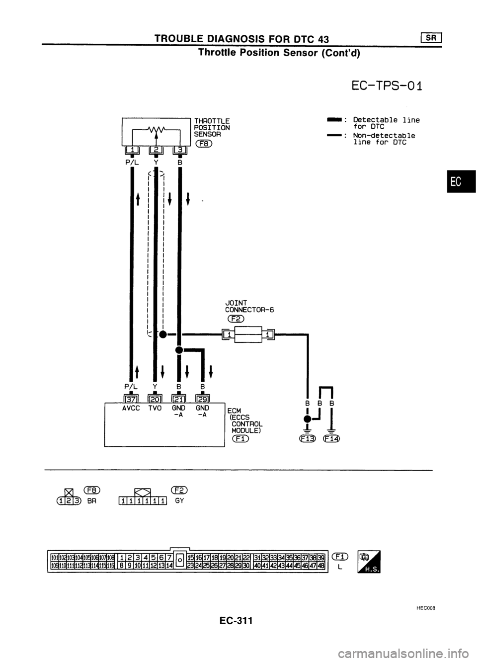
EC-TPS-01
THROTTLE
--
Detectable
line
POSITION for
DTC
SENSOR
-:
Non-detectable
@
line
forDTC
(
1
•
I
I
t
I~
~
I
I
I
I
I
I
I
I
I
I
I
I
I
I
I
I
I
I
JOINT
I
I
CONNECTOR-6
I
I
@
I
I
I I
~~
'::::
.-
t
~
i~.
P/L
Y
B
B
n
13-71 12.01
~
12-91
B
B
B
AVCC TVOGNDGND
ECM
t
J
1
-A
-A
(ECCS
CONTROL
MODULE)
CED
0:13)
m
~@
IIIillIIIIIIl
GY
CED
L
HECOOB
EC-311
Page 1031 of 1701
Repairharness orcon-
nectors.
NG
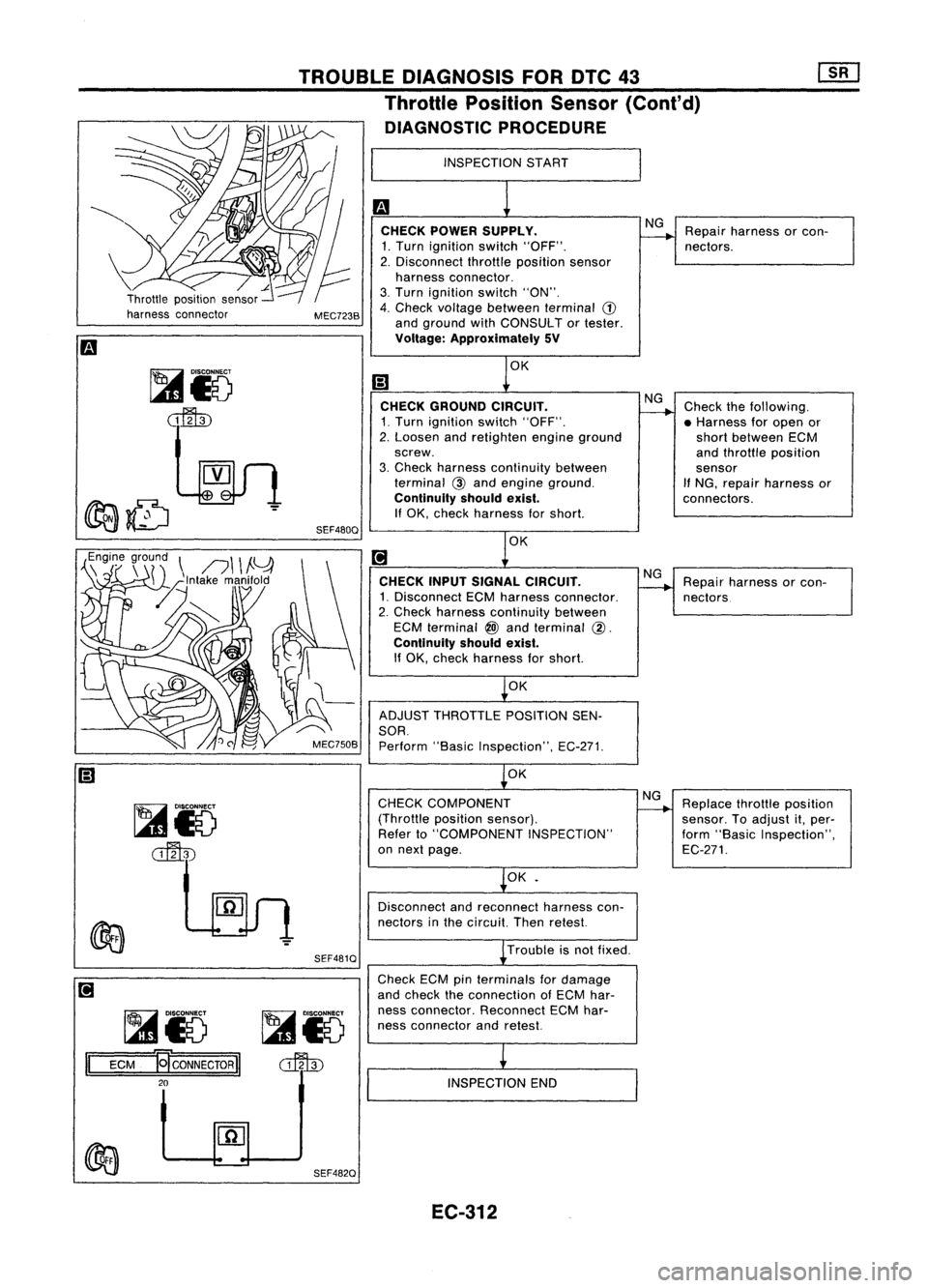
CHECK POWER SUPPLY.
1. Turn ignition switch"OFF".
2. Disconnect throttleposition sensor
harness connector.
3. Turn ignition switch"ON".
4. Check voltage between terminal
(1)
and ground withCONSULT ortester.
Voltage: Approximately 5V
INSPECTION
START
TROUBLE
DIAGNOSIS FORDTC43
Throttle Position Sensor(Cont'd)
DIAGNOSTIC PROCEDURE
MEC723B
,,~n~7
r~r~\
n\ \
!Y
-z~lntake manifold
[L~
SEF480QOK
CHECK GROUND CIRCUIT.
1. Turn ignition switch"OFF".
2. Loosen andretighten engineground
screw.
3. Check harness continuity between
terminal
@
and engine ground.
Continuity shouldexist.
If
OK, check harness forshort.
OK
CHECK INPUTSIGNAL CIRCUIT.
1. Disconnect ECMharness connector.
2. Check harness continuity between
ECM terminal
@)
and terminal
@.
Continuity shouldexist.
If OK, check harness forshort.
OK
ADJUST THROTTLE POSITIONSEN-
SOR.
Perform "BasicInspection", EC-271.
OK NG
NG
Check
thefollowing.
• Harness foropen or
short between ECM
and throttle position
sensor
If
NG, repair harness or
connectors.
Repair harness orcon-
nectors
~io
~ SEF481Q
CHECK
COMPONENT
(Throttle positionsensor).
Refer to"COMPONENT INSPECTION"
on next page.
OK•
Disconnect andreconnect harnesscon-
nectors inthe circuit. Thenretest.
Trouble isnot fixed.
NG
Replace throttleposition
sensor. Toadjust it,per-
form "Basic Inspection",
EC-271.
~io ~i5
II
ECM
~CONNECTORII
o::fl\])
20
Check
ECMpinterminals fordamage
and check theconnection ofECM har-
ness connector. Reconnect ECMhar-
ness connector andretest.
INSPECTION END
SEF482Q EC-312
Page 1032 of 1701
•
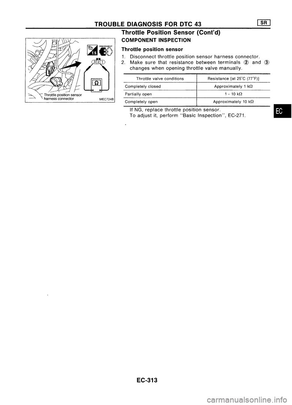
Approximately
10kQ
Resistance
[at25'C (77'Fl)
Approximately 1kQ
1 -10 kQ
If
NG, replace throttleposition sensor.
To adjust it,perform "BasicInspection", EC-271.
Throttle
valveconditions
Completely closed
Partially open
Completely open
Throttle
position sensor
1. Disconnect throttleposition sensorharness connector.
2. Make surethatresistance betweenterminals
@
and
CID
changes whenopening throttlevalvemanually.
MEC7248
TROUBLE
DIAGNOSIS FORDTC43
Throttle Position Sensor(Cont'd)
COMPONENT INSPECTION
EC-313
Page 1033 of 1701
![NISSAN ALMERA N15 1995 Service Manual TROUBLEDIAGNOSIS FORNON-DETECTABLE ITEMS[][]
Vehicle SpeedSensor (VSS)
~ R/Y
.j~
R/Y
,!1J-
R/Yi4~VEHICLE
1'TIO\1iETt\i\
~11E:w'l\ )
SPEED
~ I
'C!Qy ~
I
\Ee!6I
(SENSOR
@r
R,~ R,
[iJ NISSAN ALMERA N15 1995 Service Manual TROUBLEDIAGNOSIS FORNON-DETECTABLE ITEMS[][]
Vehicle SpeedSensor (VSS)
~ R/Y
.j~
R/Y
,!1J-
R/Yi4~VEHICLE
1'TIO\1iETt\i\
~11E:w'l\ )
SPEED
~ I
'C!Qy ~
I
\Ee!6I
(SENSOR
@r
R,~ R,
[iJ](/img/5/57349/w960_57349-1032.png)
TROUBLEDIAGNOSIS FORNON-DETECTABLE ITEMS[][]
Vehicle SpeedSensor (VSS)
~ R/Y
.j~
R/Y
,!1J-
R/Yi4~VEHICLE
1'TIO\1iETt\i\
~11E:w'l\ )
SPEED
~ I
'C!Qy ~
I
\Ee!6I
(SENSOR
@r
R,~ R,
[iJ-
R~
@@
IGNITION
SWITCH
ON
01"
START
ECM(ECCS
CONTROL BIR
MODULE)
em
-!-
@
Detectable
line
for DTC
Non-detectable line
for
DTC
EC-VSS-01
_.
-:
Refer toEL-POWER.
FUSE
BLOCK
(,JIB)
~
10A
[]]
~
PU/R
I
PU/R/U"Arn
r=:b~
I~I@
PUIR
I
PU/R
13'21
VSP
COMBINATION
METER (SPEED-
OMETER)
@
@)
r---------------------------------~
~---------------------------------~
~~
mz:rnJ
B
~@@
tW
GY
Refer
tolast page
(Foldout page).
CID
L
HEC009
EC-314
Page 1034 of 1701
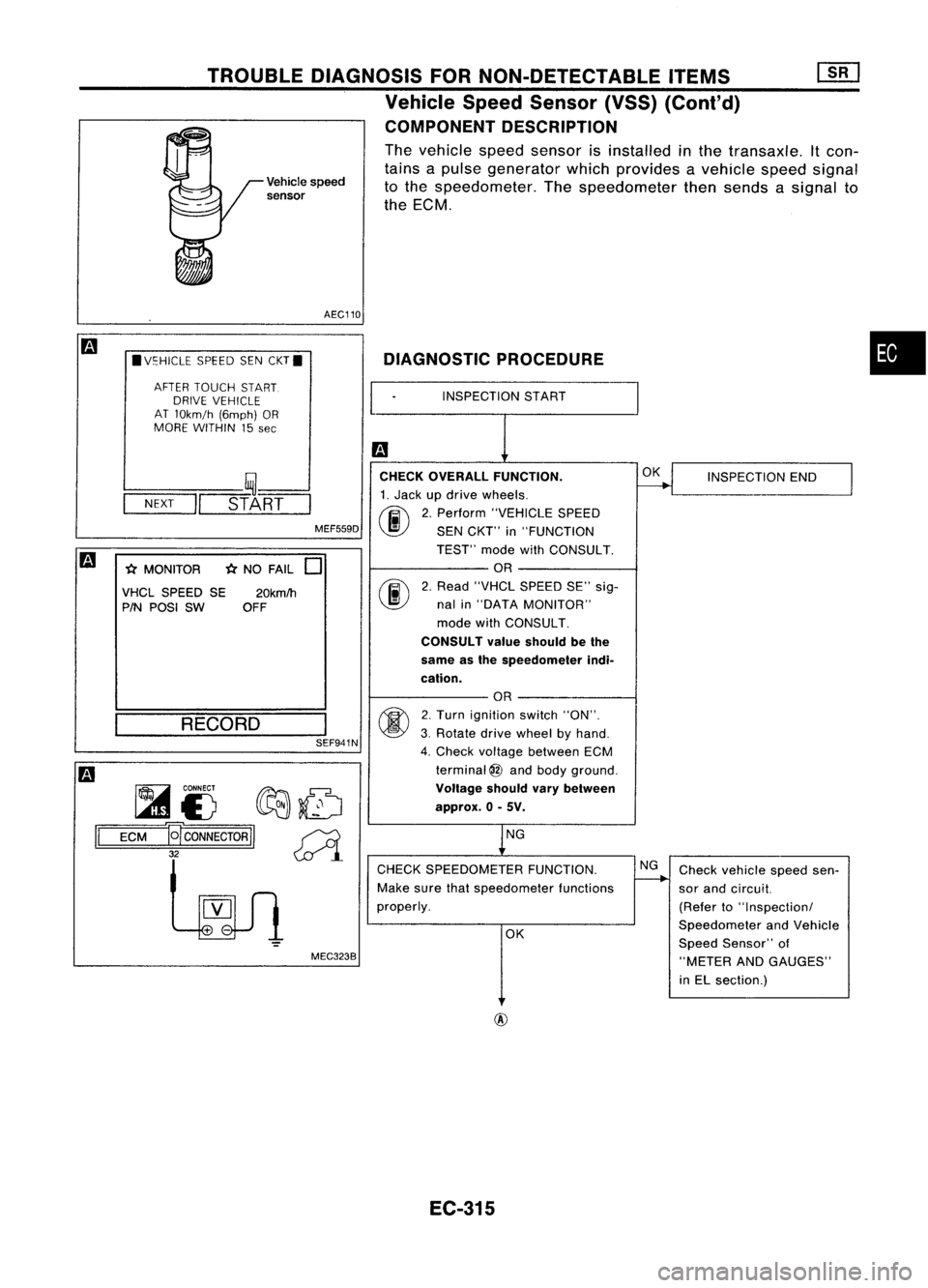
•
DIAGNOSTIC
PROCEDURE
INSPECTION START
Vehicle
speed
sensor
TROUBLE
DIAGNOSIS FORNON-DETECTABLE ITEMS
Vehicle SpeedSensor (VSS)(Conl'd)
COMPONENT DESCRIPTION
The vehicle speedsensor isinstalled inthe transaxle. Itcon-
tains apulse generator whichprovides avehicle speedsignal
to the speedometer. Thespeedometer thensends asignal to
the ECM.
AEC110
• V~HICLE SPEEDSENCKT.
AFTER TOUCH START.
DRIVE VEHICLE
AT lOkm!h (6mph)OR
MORE WITHIN 15
see
L--- __ '~----'
-N-EX-T
-1I=~_s-T_A~R=T==
MEF559D
*
MONITOR
*
NO FAIL
0
VHCL SPEED SE20kmlh
PIN POSI SW OFF CHECK
OVERALL FUNCTION.
1. Jack updrive wheels.
fi\
2.Perform "VEHICLE SPEED
~ SENCKT" in"FUNCTION
TEST" modewithCONSULT.
OR
rif\
2.Read "VHCl SPEED SE"sig-
~ nalin"DATA MONITOR"
mode withCONSULT.
CONSULT valueshould bethe
same asthe speedometer indi-
cation.
OK
INSPECTION END
RECORD SEF941N
~ CONNECT
f?Ft::J:.~
~£) ~~
1='
=E=CM=-g
CONNECTOR
II~
32
~l
MEC3238
OR
2. Turn ignition switch"ON".
3. Rotate drivewheel byhand.
4. Check voltage between ECM
terminal
@
and body ground.
Voltage shouldvarybetween
approx. 0-5V.
NG
CHECK SPEEDOMETER FUNCTION.
Make surethatspeedometer functions
properly.
OK NG
Check vehicle speedsen-
sor and circuit.
(Refer to"Inspection!
Speedometer andVehicle
Speed Sensor" of
"METER ANDGAUGES"
in El section.)
@
EC-315
Page 1035 of 1701
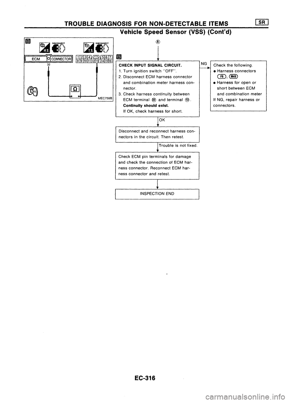
Checkthefollowing.
• Harness connectors
CID,@
• Harness foropen or
short between ECM
and combination meter
If
NG, repair harness or
connectors.
NG
CHECK INPUTSIGNAL CIRCUIT.
1. Turn ignition switch"OFF".
2. Disconnect ECMharness connector
and combination meterharness con-
nector.
3. Check harness continuity between
ECM terminal
@
and terminal
@.
Continuity shouldexist.
If OK, check harness forshort.
MEC7598
TROUBLE
DIAGNOSIS FORNON-DETECTABLE ITEMS
Vehicle SpeedSensor (VSS)(Cont'd)
@
@I
CONNECTOR
I
32
ECM
OK
Disconnect andreconnect harnesscon-
nectors inthe circuit. Thenretest.
Trouble isnot fixed.
Check ECMpinterminals fordamage
and check theconnection ofECM har-
ness connector. ReconnectECMhar-
ness connector andretest.
INSPECTION END
EC-316
Page 1038 of 1701
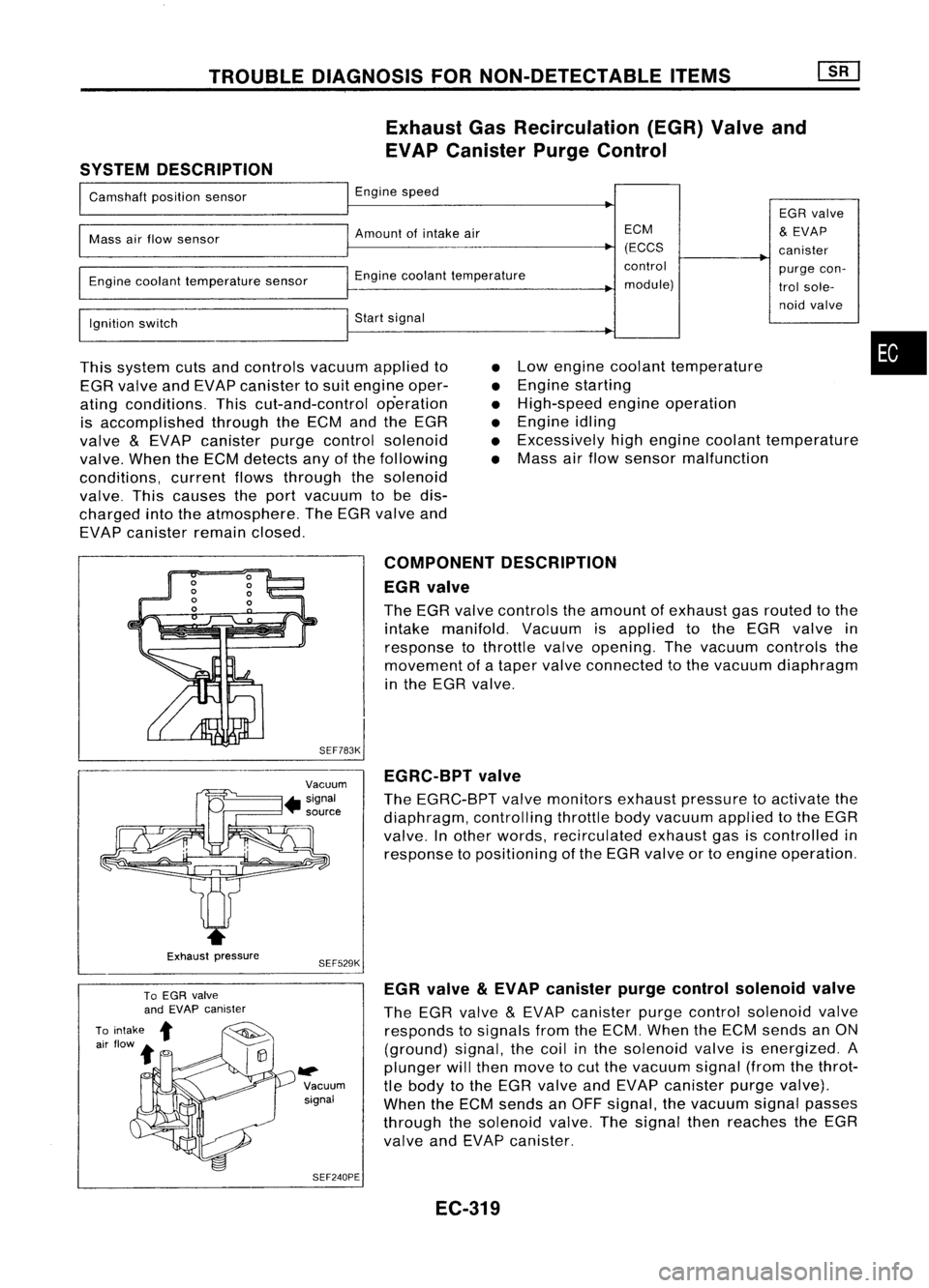
TROUBLEDIAGNOSIS FORNON-DETECTABLE ITEMS
Exhaust GasRecirculation (EGR)Valveand
EVAP Canister PurgeControl
SYSTEM DESCRIPTION
I
Camshaft positionsensor
I
Engine speed
EGRvalve
I
Mass
airflow sensor
I
Amount ofintake air ECM
&
EVAP
(ECCS canister
I
~Engine
coolanttemperature control
purgecon-
Engine coolant temperature sensor
module)trolsole-
I
noid
valve
Ignition switch
I
Start signal
I
This system cutsandcontrols vacuumappliedto
EGR valve andEVAP canister tosuit engine oper-
ating conditions. Thiscut-and-control operation
is accomplished throughtheECM andtheEGR
valve
&
EVAP canister purgecontrol solenoid
valve. WhentheECM detects anyofthe following
conditions, currentflowsthrough thesolenoid
valve. Thiscauses theport vacuum tobe dis-
charged intotheatmosphere. TheEGR valve and
EVAP canister remainclosed.
•
•
•
•
•
•
Low
engine coolant temperature
Engine starting
High-speed engineoperation
Engine idling
Excessively highengine coolant temperature
Mass airflow sensor malfunction
•
Exhaust pressure COMPONENT
DESCRIPTION
EGR valve
The EGR valve controls theamount ofexhaust gasrouted tothe
intake manifold. Vacuumisapplied tothe EGR valve in
response tothrottle valveopening. Thevacuum controls the
movement ofataper valve connected tothe vacuum diaphragm
in the EGR valve.
SEF783K EGRC-BPT valve
The EGRC-BPT valvemonitors exhaustpressure toactivate the
diaphragm, controllingthrottlebodyvacuum appliedtothe EGR
valve. Inother words, recirculated exhaustgasiscontrolled in
response topositioning ofthe EGR valve ortoengine operation.
SEF529K
~ Vacuumsignal
SEF240PE EGR
valve
&
EVAP canister purgecontrol solenoid valve
The EGR valve
&
EVAP canister purgecontrol solenoid valve
responds tosignals fromtheECM. When theECM sends anON
(ground) signal,thecoil inthe solenoid valveisenergized. A
plunger willthen move tocut the vacuum signal(fromthethrot-
tle body tothe EGR valve andEVAP canister purgevalve).
When theECM sends anOFF signal, thevacuum signalpasses
through thesolenoid valve.Thesignal thenreaches theEGR
valve andEVAP canister.
EC-319
Page 1046 of 1701
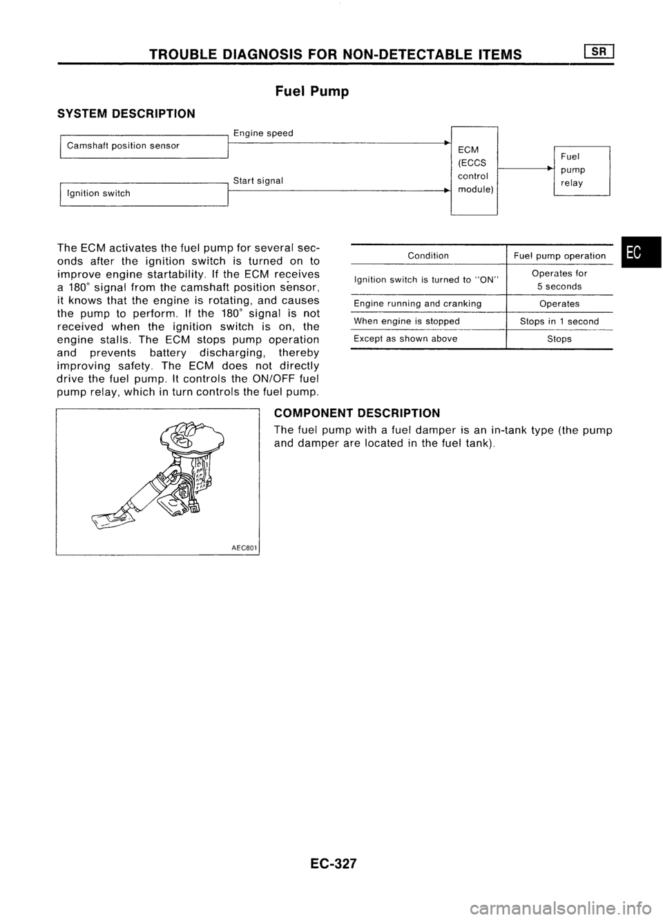
TROUBLEDIAGNOSIS FORNON-DETECTABLE ITEMS
Fuel Pump
SYSTEM DESCRIPTION
I
Camshaft positionsensor
I
Engine speed
~
ECM
(ECCS Fuel
control pump
!,gnition switch Start
signal
relay
I
module)
The ECM activates thefuel pump forseveral sec-
onds aftertheignition switchisturned onto
improve enginestartability. Ifthe ECM receives
a 180
0
signal fromthecamshaft positionsensor,
it knows thattheengine isrotating, andcauses
the pump toperform. Ifthe 180
0
signal isnot
received whentheignition switchison, the
engine stalls.TheECM stops pump operation
and prevents batterydischarging, thereby
improving safety.TheECM does notdirectly
drive thefuel pump. Itcontrols theON/OFF fuel
pump relay,which inturn controls thefuel pump.
Condition
Ignition switchisturned to"ON"
Engine running andcranking
When engine isstopped
Except asshown above Fuel
pump operation •
Operates for
5 seconds
Operates
Stops in1second
Stops
COMPONENT DESCRIPTION
The fuel pump withafuel damper isan in-tank type(thepump
and damper arelocated inthe fuel tank).
AECB01
EC-327
Page 1051 of 1701
TROUBLEDIAGNOSIS FORNON-DETECTABLE ITEMS
Idle AirControl Valve(IACV)-Air Regulator
SYSTEM DESCRIPTION
Camshaft positionsensor
Ignition switch Engine
speed
Start signal ECM
(ECCS
control
module) IACV-air
regulator
The IACV-air regulator iscontrolled bythe ECM
at the same timeasfuel pump ON-OFF control.
Condition
Ignition switchisturned to"ON"
Engine running andcranking
When engine isstopped
Except asshown above IACV-air
regulator
operation
Operates for5
seconds
Operates
OFF in1second
OFF
Bimetal
...
Air flow
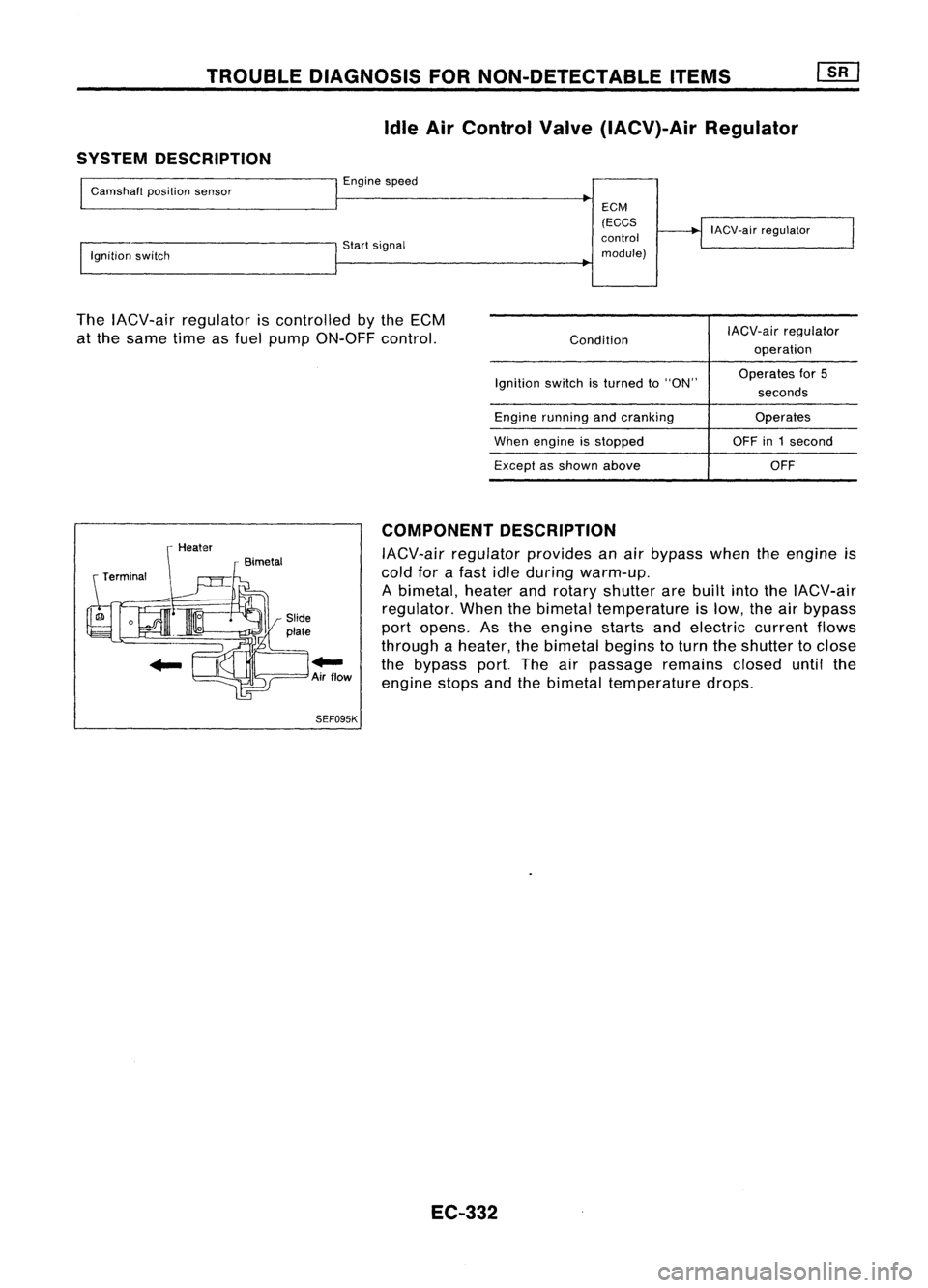
SEF095K COMPONENT
DESCRIPTION
IACV-air regulator providesanair bypass whentheengine ;s
cold forafast idleduring warm-up.
A bimetal, heaterandrotary shutter arebuilt intotheIACV-air
regulator. Whenthebimetal temperature islow, theairbypass
port opens. Asthe engine startsandelectric currentflows
through aheater, thebimetal beginstoturn theshutter toclose
the bypass port.Theairpassage remainscloseduntilthe
engine stopsandthebimetal temperature drops.
EC-332