NISSAN ALMERA N15 1995 Owner's Manual
Manufacturer: NISSAN, Model Year: 1995, Model line: ALMERA N15, Model: NISSAN ALMERA N15 1995Pages: 1701, PDF Size: 82.27 MB
Page 21 of 1701
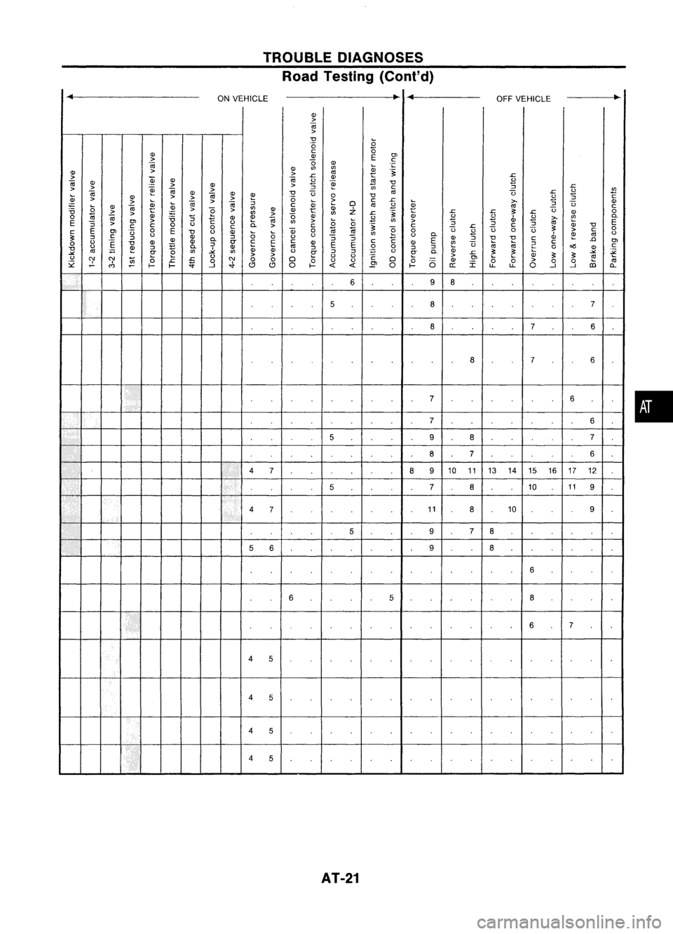
TROUBLEDIAGNOSES
Road Testing (Cont'd)
...
ONVEHICLE
..
...
OFFVEHICLE ~
Q)
>
Iii
>
~ ~
0
B
Q)
c:::
0
OJ
>
~
E
c:::
Iii
0
Q)
~
";:
Q)
'"
'"
Q)
>
>
nl
ill
"~
>
.r:
Q)
~
.r:
Iii
Q)
Qi
Q)
Iii
.B
~
"0
u
>
Q)
>
:;
.r:
> >
~
Iii
>
~
'"
c:::
u
tl
Iii
Q)
"0
U
nl
U
.r:
~ Q)
>>
Iii
Q)
~
0
"0
.B
:;
c:::
Q)
>
>
~
>>
0
~
~
c:::
.r:
(j;
>-
Q)
;;::
(;
Q)
Iii
Q)
~
Oi
Oi
~
c:::
Q)
D
nl
.B
nl
~
U
c:::
'6
>
~
>
"2
>
'"
Q)
Q)
t
Q)
Z
"~
t
.r: .r:
~
.r:
U
Q)
0
>
'"
>
'"
.r:
0
c;;
Iii
:;
1: Q)
Q)
Oi
(5
Q)
.B
Q)
.B
u
.B
>-
~
0-
E OJ
>
"0
u
Ci
'"
>
(;(;
'"
>
:;
Q)
nl
E
~
>
c::: c:::
0
u
c:::
>
c:::
"~
c:::
~
.r:
c:::
~
Q)
"0
E
0
E
0
Qj
0
~ ~
"2
0
u
u
0
U
~
>
c:::
0
c:::
OJ
U
u
"0
u
Q)
~
(;
u
'"
u
0-
.B
~
nl
u
~ ~
c:::
~ Q)Q)
0-
~
0
(J
~~
1: EQ)
~
"0 "0
c:::
Q)
.Q
0
(J
"E
"0
Q)
Q)
CT
c:::
c:::c:::
Q)
EE
c:::
Q)
~
u
tiitii
;:
c:::
OJ
(J
~
~
0-
~
Q)
(j;(j;
nl
~
0
0
~~
0
o1S
Q)
c:::
"0
nl
:;:;
~
CT
'"
~
'"
(J
CT
~
~
E
(J
CT
0-
Q)
.r:
~~
(j;
-'"
~
-'"
(J
>
>
(J
(J
>
~~
~
(J
'}' '}'
ii)
(;
.r:
N
00
D
(;
c:::
D
(;
Q)OJ
(;
(;
>
tii
~
.r:
0
(J
(J
(5
I
0
0
~
C")
~
l-
I-
::
.}
~ ~
0
I-
<{
<{
E'
0
l-
e::
LL
LL
0
..J..J
lD
0..
6 9
8
I
5
8
7
8
76
8
76
• 7
6
7 6
5 9
8
7
8
7 6
A
4
7
8
910
1113 1415 1617 12
5 7
8
1011
9
4 7 11
8
10
9
5 97
8
5 6 9
8
6
6 5
8
If
6
7
4 5
4 5
4
5
I[
4
5
AT-21
•
Page 22 of 1701

TROUBLEDIAGNOSES
Road Testing (Cont'd)
Numbers arearranged inorder ofprobability.
~
ONVEHICLE
..
Perform inspections startingwithnumber one
and work up.
Circled numbers indicatethatthetransaxle
must beremoved fromthevehicle.
(J)(J)
> >
01
0;
0;
. Valve expected tobe malfunctioning
c:
>
(J)
~ .;::
>>
(J)
.~
c
0;
>
0;
(J)
>
e
0;
"0 "0
Q)
C
>
::J
c:(J)
.8
rr
III
(J)
"0
0
~
0.
oil
III
<.>
'0
J::.
rtl
:;
J::.
ii
(J)
£
~(J)
(J)
(J) (J)
(J)(J)
£
"0
.~
~
01
>>
>
01
>>>
0
c: :0 c:
::J
0;0;
~
0;
0;0;
::J
E
III III
rtl
.~
rtl
0;
(3
<.>
~
rtl
>>
> >
>>
a; ~
(J) ~ (J)~
;:
'E
;t:
c:
~
>
e
.8
E (J)
0.
e
E
0;
::J
J::. J::.
:c
2
::J
~
:0
.!::
::J
rtl
rtl
C
e
(J)
c
0
c:
rtlrtl
rtlrtl
li;
rtl
J::.
01
c:
.c
III
(J)
"'f
C')
C)'
>
(J)
6
0
J::.
c:
0
a: a:
u
EO
~
UJ
::i
u
~
::E
C')
N
0
Failure tochange gearfrom 4th
to 2nd with accelerator pedal
32
6
depressed.
Failure tochange gearfrom3rd
to 2nd with accelerator pedal
32
6
depressed.
Failure tochange gearfrom 1st
32
6
to 2nd in"0" and"2"position.
Shift quality Vehicledoesnotstart from
32
6
"1st" in"0" and"2"position.
Failure tochange gearto3rd
32
6
and 4thin"0" position.
Changes gearto1st directly
when selector leverisset from
32
6
"D"
to"1" position.
Changes gearto2nd in"1"
3
2
6
position.
Lock-up pointisextremely high
32
6
or low.
Lock-up quality Torque
converter doesnotlock-
32
7
up.
Lock-up isnot released when
2
accelerator pedalisreleased.
Engine doesnotstart in"P" and "N" positions orengine starts
2
3
in positions otherthan"P"and "N" positions.
Vehicle moveswithselector leverin"P" position.
AT-22
Page 23 of 1701
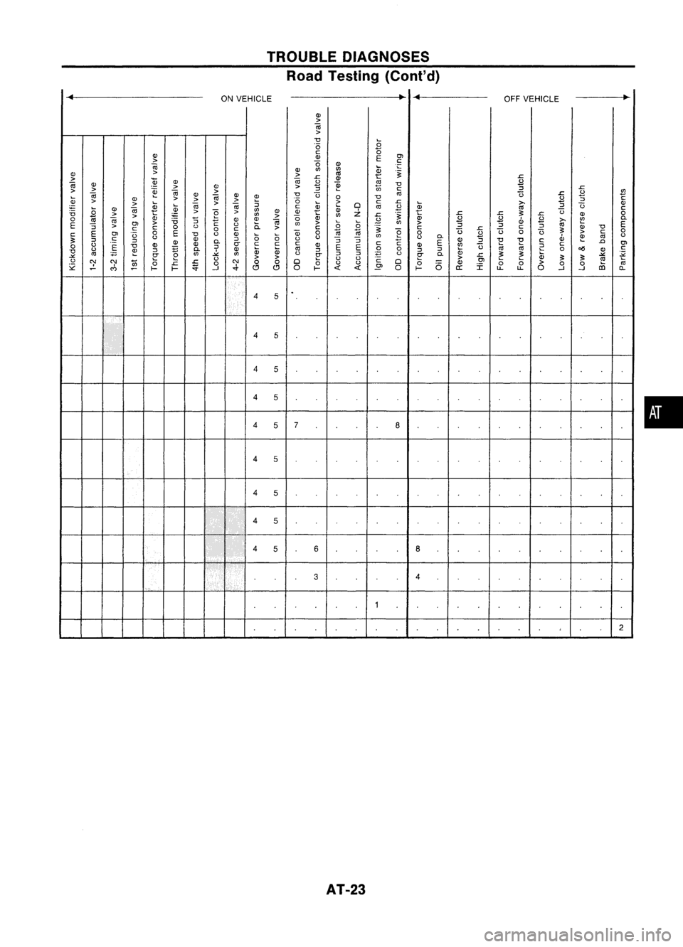
TROUBLEDIAGNOSES
Road Testing (Conl'd)
...
ONVEHICLE ~
...
OFFVEHICLE ~
QJ
>
OJ
>
"0
...
.0
0
QJ
c:
(5
Ol
QJ
E
>
(5
c:
OJ
QJ
...
.
.:;
QJ
enen
QJ
>
>
'"
~
.~
.s::
>
~
OJ
.s::
QJ
OJ
QJ QJ
.B
~ ~
"0
.B
> >
QJ
>
::l
en
c:
::l
.s::
>
OJ
~
OJ
QJ
>
"0
t3
'"
t3
.s::
.B
.!!l
...
>
OJ
QJ
~
0
"0
.B
c:
QJ
>
QJ
>>
.0
>
c:
.s::
::l
>
...
OJ
>
OJ
::l
2
Cl
Qi
>-
::l
t3
QJ
~
2
~ c:
Qi
'"
.B
'"
c:
.8
QJ
OJ
>
e
>
en
QJ
~
Z
t
:;:
t3
"0
>
>
Qi
en
>
Qi
en
.s::
.~
.s::
.s::
.s::
QJ
0
0
OJ
"5
QJ
QJ
0
.B
QJ
.B .B
d>
.B
>-
~
0.
E ~
Ol
>
"0
1:
()
0.
OJ
en
>
00
en
>
::l ::l
'"
E
::l
>
c:c:
0
()
0
c:
>
c:
.~
c:
.s::
c:
::l
:;:
QJ
"0
E
Ol
.0
0
E
"0
()
QJ
Q)
0
1ii 1ii
e
0
u
.B
t3
0
t3
>
c:
0
c:
()
0
a
()
en
()
0.
d>
~
()
:;:
::l
.~
::l
QJQJ
0.
::l
()
::l::l
1: E
QJ
::l
"0 "0
c:
.0
Ol
()
QJ
0-
c:
c:c:
QJ
c:
QJ
en
:a:a
c:
0
E
"0
QJ
l'
E
E
t3
t
c:
()
::l
E
0.
QJ
QiQi
'"
::l
0
0
::l::l
Qi
0
o(l
QJ
"0
~
en
-"
en
()
::l::l
E
()
0.
~
:;:
-"
:;:
-"
2"
2
2"
0-
.s::
()
()
>
>
Cl
()
()
c:Cl
0
>
Ol
0
QJ
:;::;:
'"
:a
'}' '}'
u;
0
.s:: .s::
0
N
00
0
()
()
<5
QJ
I
0
>
00
m
~
C')
~
f- f-
::;
..J
..,;.
Cl Cl
0
f-
<{
<{
~
0
f-
a:
u..u..
0
..J..J 0-
4
5
4
5
4
5
4
5
4
5
7
8
4
5
4
5
4
5
4
5
6
8
rr
3
4
1
2
AT-23
•
Page 24 of 1701

TROUBLEDIAGNOSES
Stall Tasting
STALL TESTPROCEDURE
1. Check
AIT
and engine fluidlevels. Ifnecessary, addfluid.
2. Drive vehicle forabout 10minutes untilengine oiland ATF
reach operating temperature.
ATF operating temperature:
50 -80
0
e (122-176°F)
SAT6478
3.Set parking brakeandblock wheels.
4. Install atachometer whereitcan beseen bydriver during
test.
SAT513G 5.
~ ~ID
•
~c;>
SAT7678
Start
engine, applyfootbrake, andplace selector leverin
"0"
position.
6. Accelerate towide-open throttlegradually whileapplying
foot brake.
7. Quickly notetheengine stallrevolution andimmediately
release throttle.
• During test,never holdthrottle wide-open formore than5
seconds. Stall revolution .standard:
Refer toSDS, AT-166.
SAT514G
8.Move selector leverto"N" position.
9. Cool offATF.
• Run engine atidle foratleast oneminute.
10. Repeat steps5through 9with selector leverin"2", "1"and
"R
n
positions.
SAT7718 AT-24
Page 25 of 1701

JUDGEMENT OFSTALL TEST
Selector leverposition
TROUBLE
DIAGNOSES
Stall Tasting (Cont'd)
Judgement
D
2
R
Damaged components
Forward one-way
cluth
Hydraulic circuitfor
line pressure control
(Line pressure islow.)
D
2
R
Selector leverposition H
H
H
o
H
H
H
H
o
o
o
H
o
o
o
o
Judgement
AT-25
L
L
L
L
o
:
Stall
revolution
isnormal.
H :Stall revolution ishigher
than specified.
L :Stall revolution islower
than specified.
Engine
Torque converter
one-way clutch
Reverse clutch
Low one-way clutch
Clutches andbrakes except
high clutch, brakebandand
overrun clutchareOK.
(Condition ofhigh clutch,
brake bandandoverrun
clutch cannot beconfirmed by
stall test.)
SAT871H
•
Page 26 of 1701

TROUBLEDIAGNOSES
Pressure Testing
• Location ofpressure testport.
• Always replace pressure plugsasthey areself-sealing
bolts.
Test portfor
line pressure governor
pressure
SAT565D
LINEPRESSURE TESTPROCEDURE
1. Check AfTand engine fluidlevels. Ifnecessary, addfluid.
2. Drive vehicle forabout 10minutes untilengine oiland ATF
reach operating temperature.
ATF operating temperature:
50 -80°C (122-176°F)
SAT647B
3.Install pressure gaugetoline pressure port.
4. Set parking brakeandblock wheels.
Continue todepress brakepedalfullywhile performing line
pressure testatstall speed.
SAT513G
5.Start engine andmeasure linepressure atidle and stall
speed. Line pressure:
Refer toSOS, AT-166.
JUDGEMENT OFLINE PRESSURE TEST
• Ifline pressure doesnotrise, firstcheck tomake surethat
throttle wireisconnected properly.
1) When linepressure whileidling
is
low atall positions ("D",
"2", "1", "R"and"P"), theproblem maybedue to:
SAT494G •
Wear oninterior ofoil pump
AT-26
Page 27 of 1701

'-)
(
~)o
Front
SAT498GTROUBLE
DIAGNOSES
Pressure Testing(Cont'd)
• Oilleakage ator around oilpump, control valvebody, trans-
mission caseorgovernor
• Sticking pressure regulator valve
• Sticking pressure modifiervalve
2) When linepressure whileidling islow ataparticular
position, checkthefollowing.
• Ifoil leaks ator around low
&
reverse brakecircuit, line
pressure becomes lowin"R" position. Butline pressure is
normal in"P", "D", "2"or"1" position.
3) When linepressure ishigh while idling, pressure regulator
valve mayhave stuck.
GOVERNOR PRESSURETESTING
1. Check
AIT
and engine fluidlevels. Ifnecessary, addfluid.
2 .. Drive vehicle forabout 10minutes untilengine oiland ATF
reach operating temperature.
ATF operating temperature:
50 -80°C (122-176°F)
3. Install pressure gaugetogovernor pressureport.
4. Set parking brakeandblock rearwheels.
5. Jack upfront wheels.
6. Set selector leverinDposition anddrive vehicle.
Be careful ofrotating wheels.
•
Governor pressure:
• Governor pressureisnot generated whenvehicle is
stopped. (frontwheels arenotrotating.)
• Governor pressurerisesgradually inresponse tovehicle
speed. (frontwheel rotating speed.)
If not, check governor valveassembly. RefertoAT-36.
AT-27
Page 28 of 1701
TROUBLEDIAGNOSES
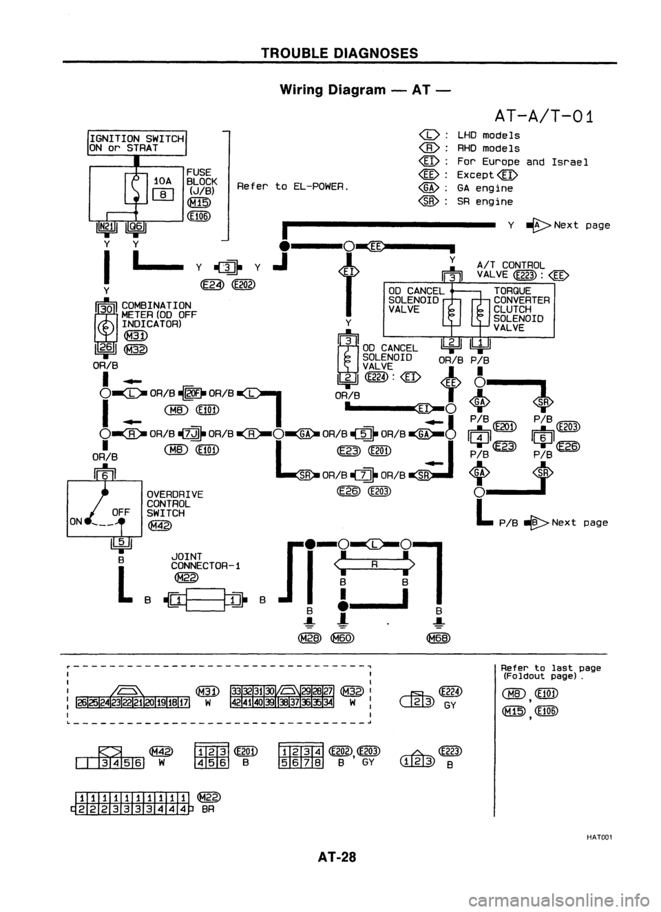
Wiring Diagram -AT -
AT-A/T-01
page
Israel
Y ~Next page
A!T CONTROL
VAL VE
(E223) :
@
TORQUE
CONVERTER
CLUTCH
SOLENOID
VALVE
LHD
models
RHO models
For Europe and
Except@
GA engine
SR engine
(b):
:
@:
@:
@:
@:
Refer
toEL-POWER.
FUSE
BLOCK (J!B)
([@
(El06)
I
y ~.~ y
l---t~'~
Y ~(E202)
III
C~INATION
METER
(00OFF
INDICATOR) Y
~ t~)
11
2•6
1
@
300 CANCEL ~~
SOLENOID OR!BP!B
OR!B VALVE
I .-
I!::iJl
(E224) :
@
4~~
O~
OR!B
~1-
DRIB
I
OR!B
T
A
I
(BID
(Elan •
~o~
SR
.- .-1
P!B@l) P!B~
O~
OR!B~ DRIB
-ea-O~
OR!B~ OR!B
~O
/I;
II
E20l
II
i
II
E203
ORI!B
CBID
(El0n
L
@
(E20n
I
P!B~ P!B~
rm
SR
OR!B
-cz::n.
OR!B~
<0> ~
OVERDRIVE (E?6)
(E203)
0--1
CONTROL
L
OFF SWITCH
~ PIB-@>Next
ON
~
B
L
JOINT
CONNECTOR-1
~
B
~==~
B
r---------------------------------,
~(E224)
~GY
L ~
Refer
tolast page
(Foldout page).
CHID
(EtOn
,
([@
(El06)
,
~~
~W
~@D
~ B
~
(E202),~ ~
@J)
rn:rn:rz::rnJ
BGY
W@
B
ITIII:illIillIi ~
~ BR
HAT001
AT-28
Page 29 of 1701
•
(b):
LHDmodels
:
RHOmodels
@:
Except forEurope
and Israel
~: GAengine forAustralia
@:
Except@
*1 ...
@
30
@
115
,
ECM
(ECCS
CONTROL
MODULE)
em
_ INHIBITOR
P .. ..1P ..
-1
SWITCH
R N-0 2 R
~-o
2
@g)
TROUBLE
DIAGNOSES
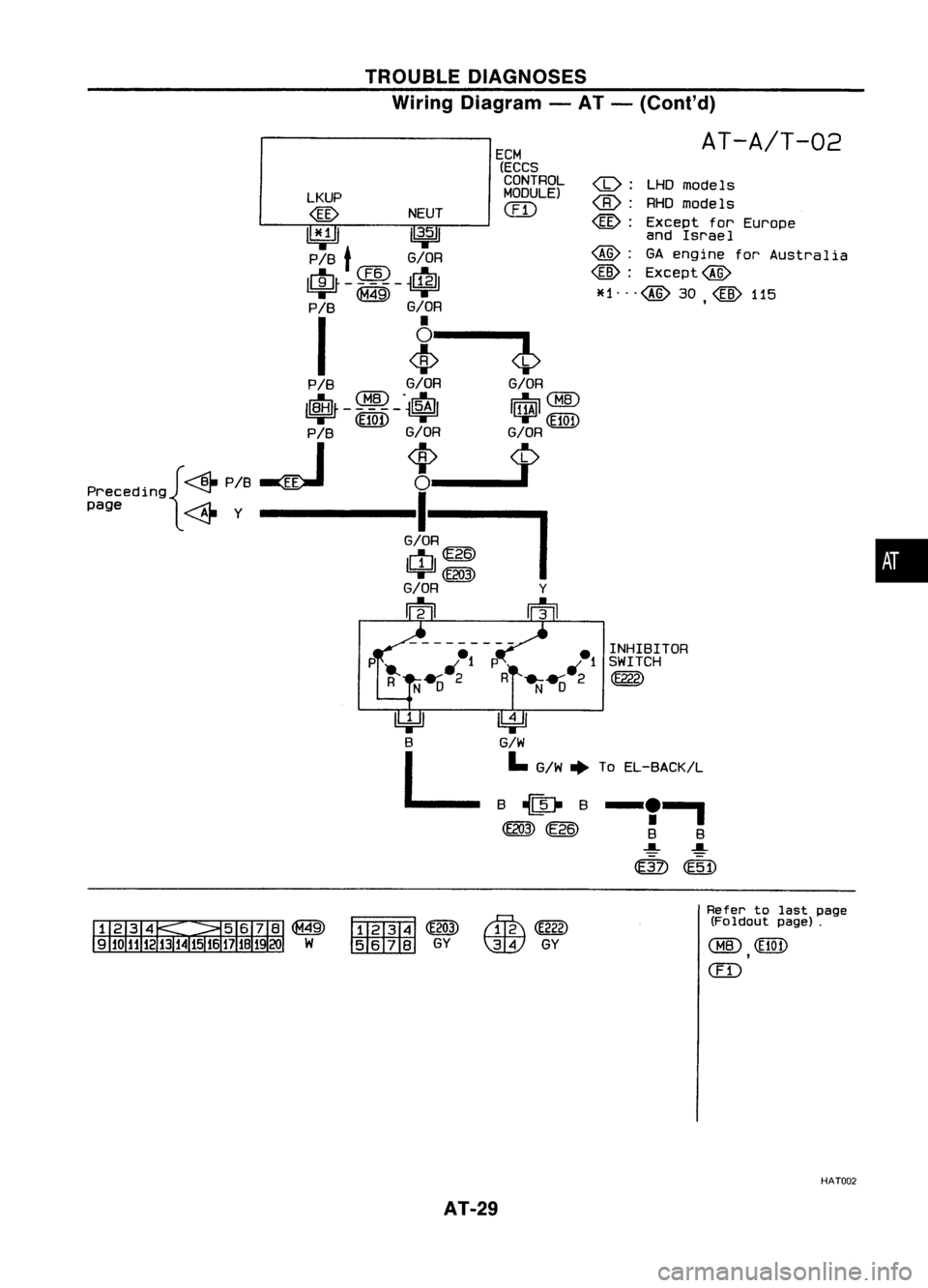
Wiring Diagram -AT -(Coni' d)
AT-A/T-02
LKUP
@
NEUT
I1¥Jl
11
3•5
1
P/B
t
G/OR
~CIID~
~-
I
i
P /B G/OR G/OR
~ CHID.
dI:-. ~
CHID
ll\tlJr -
$100 -~
I~I
P/B G/OR G/OR
. {~P/8~
*_1>
Precedlng ~
I
page ~Y-------G/O~
IUJI~
=w=
(E203)
G/OR Y
m rn
l!4='J
B
L
~
G/W
I.
G/W ~ToEL-BACK/L
-'I
B B
~ ~
@)
@j)
~
~ GY
~
(E222)
\IDY
GY Refer
tolast page
(Foldout page).
CHID
(EI0t)
,
(ill
HAT002
AT-29
Page 30 of 1701
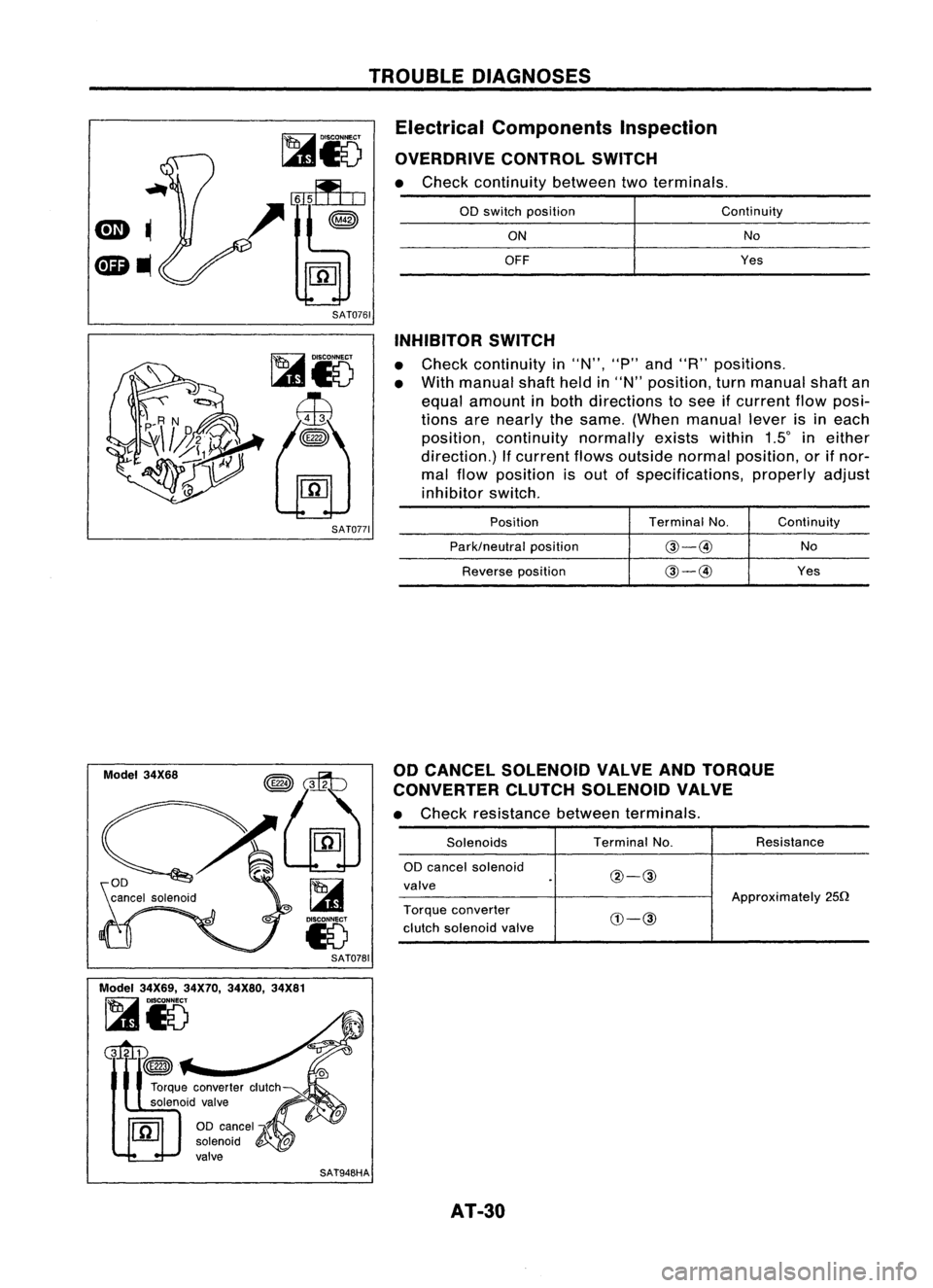
TROUBLEDIAGNOSES
Electrical Components Inspection
OVERDRIVE CONTROLSWITCH
• Check continuity betweentwoterminals.
SAT0761
00
switch position
ON
OFF
Continuity
No
Yes
SAT0771
Model 34X68
SAT0781
Model 34X69, 34X70,34X80, 34X81
~i5
Gltm
~
SAT948HAINHIBITOR
SWITCH
• Check continuity in"N", "P"and "R" positions.
• With manual shaftheldin"N" position, turnmanual shaftan
equal amount inboth directions tosee ifcurrent flowposi-
tions arenearly thesame. (When manual leverisineach
position, continuity normallyexistswithin 1Sineither
direction.) Ifcurrent flowsoutside normalposition, orifnor-
mal flow position isout ofspecifications, properlyadjust
inhibitor switch.
Position TerminalNo. Continuity
Park/neutral position
@-@
No
Reverse position
@-@
Yes
00 CANCEL SOLENOID VALVEANDTORQUE
CONVERTER CLUTCHSOLENOID VALVE
• Check resistance betweenterminals.
Solenoids TerminalNo. Resistance
00 cancel solenoid
@-@
valve
Approximately250
Torque converter
CIJ-@
clutch solenoid valve
AT-30