NISSAN ALMERA N15 1995 Service Manual
Manufacturer: NISSAN, Model Year: 1995, Model line: ALMERA N15, Model: NISSAN ALMERA N15 1995Pages: 1701, PDF Size: 82.27 MB
Page 791 of 1701
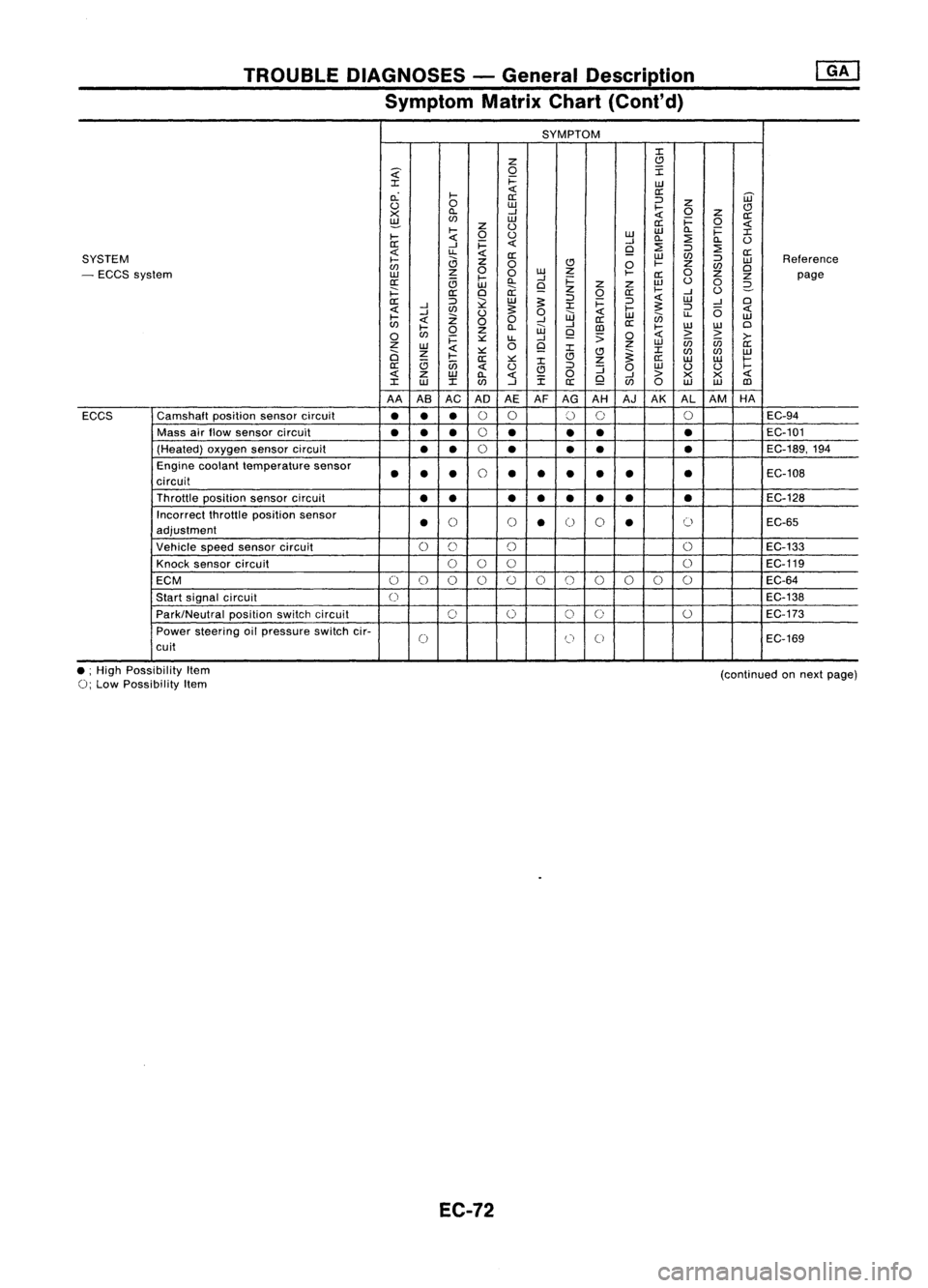
TROUBLEDIAGNOSES -General Description
Symptom MatrixChart(Cont'd)
SYMPTOM
:I:
Z
C)
~
0
I
:I:
i=
UJ
c.:
I-
«
a:
[ij'
a:
:J
u
0
UJ
I-
Z
C)
X
ll.
--l
«
0
z
a:
~
(f)
UJ
a:i=
0
«
I-
z
U
UJ
ll.
i=
:I:
I-
«
0
u
UJ
ll.
:2
ll.
U
a:
--l
i=
«
--l
:2
9
:J
:2
«
u.
«
a:
UJ
(f)
a:
SYSTEM
I-
a
z
:J
UJ
Reference
(f)
0
C)
0
I-
Z
(f)
Cl
- ECCS system
UJ
z
0
0
w
Z
I-
a:
0
z
z
page
a:
c;
l-
ll.
--l
i=
w
u
0
UJ
9
z
z
2-
i==:
a:
Cl
ii:
z
0
a:
I-
--l
U
a::
:J
l2
UJ
~
:J
i=
:J
«
UJ
--l
Cl
«
--l
(f)
~
:I:
I-
~
:J
(5
«
I-
--l
Z
U
0
UJ
«
UJ
en
u.
UJ
«
00
--l
a::
(f)
l-
ll.
W
--l
[])
a::
I-
w
W
Cl
0
(f)
0
z
9
;;
0
«
>
>
>-
i=
::.::
u.
--l
Z
0
9
z
UJ
in in
a::
UJ
«
:I:
:I:
a
z
I-
::.::
C)C)
~
(f)
(f)
UJ
a::
::.::
:I:
z
a::
UJ UJ
I-
a::
c;
in
«
u
C)
:J
:J
0
UJ
U U
I-
«
z
UJ
ll.
«
i
0
9
--l
>
X X
«
:I:
w
:I:(f)
--l
a::
(f)
0
UJ UJ
[])
AA ASAC AD AEAFAG AH AJAK ALAM HA
ECCS Camshaft
positionsensorcircuit
•••
0
0
()
0 0
EC-94
Mass airflow sensor circuit
••
•
0
•
••
•
EC-101
(Heated) oxygensensorcircuit
••
0
• •
•
•
EC-189,194
Engine coolant temperature sensor
••
•
0
••
•
•
•
•
EC-108
circuit
Throttle position sensorcircuit
•• ••• ••
•
EC-128
Incorrect throttleposition sensor
•
()
()
•
0
0
•
()
EC-65
adjustment
Vehicle speedsensor circuit
0
C)
()
0
EC-133
Knock sensor circuit
000 0
EC-119
ECM
0
()
0 0
()
0
()
()()
0 0
EC-64
Start signal circuit
0
EC-138
Park/Neutral positionswitchcircuit
0
0
0
0
0
EC-173
Power steering oilpressure switchcir-
0
(J
0
EC-169
cuit
• ;High Possibility Item
0;
Low Possibility Item
EC-72
(continued
onnext page)
Page 792 of 1701
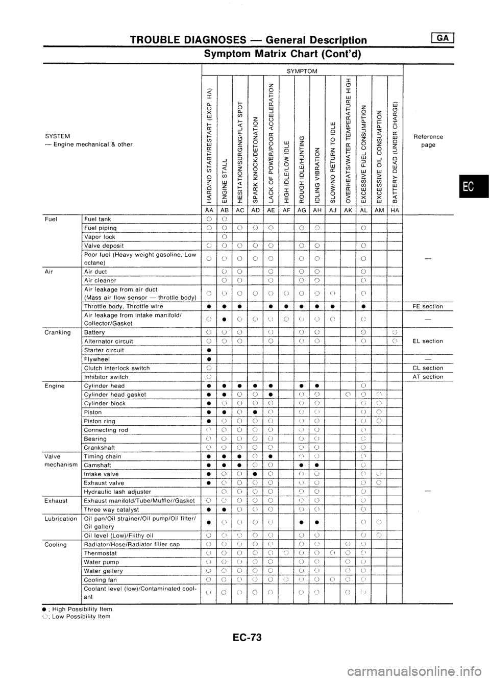
TROUBLEDIAGNOSES -General Description
Symptom MatrixChart(Cont'd)
SYMPTOM
J:
Z
CJ
~
0
I
J:
i=
LU
cL
I-
«
a:
a: ::J
UJ
0
0
LU
I-
Z
CJ
><
D..
-'
«
0
z
a:
~
LU
i=
0
z
0
a:
«
I-
0
0
LULU
D..
i=
J:
I-
«
-'
D..
:2
D..
0
0:
-'
i=
«
9
:2
::J
:2
SYSTEM
«
LL
«
0:
LU
C/J
a:
I-
0
Z
0
CJ
0
I-
Z
::J
LU
Reference
C/J
0
C/J
0
- Engine mechanical
&
other
z
0
LU
Z
I-
0
LU
I-
-'
0:
Z
Z
page
0:
(3
LU
D..
9
i=
z
Z
LU
0
0
2-
;:::
a:
0
a:
z
0
a:
I-
-'
0
0:
::J
~
LU
5:
::J
i=
::J
«
LU
-'
0
-'
J:
5:
«
-'
C/J
0
5:
0
«
I-
::J
(5
«
I-
Z
W
LU
en
LL
LU
C/J
«
00
-'
-'
a:
a:
0
I-
0
Z
D..
W
CD
I-
LU
LU
0
C/J
i=
~
LL
-'
9
:>
0
«
>
~
>-
z
0
Z
LU
(ij
C/J
a:
LU
«
~
9
J:
J:
0
Z
CJ
~
C/J
C/J
LU
I-
0:
~
CJ
Z
a:
LU LU
I-
(3
(jj
J:
a:
«
0
CJ
::J
:J
0
LU
0 0
I-
«
z
LU
D..
«
0
-'
>
><><
«
J:
LU
J:
C/J
-'
J:
a:
9
C/J
0
LU LU
CD
AA ASAC AD
AEAF
AG AH AJAK ALAM HA
Fuel Fueltank
0
U
Fuel piping
00 0
()
0 00 0
Vapor lock
U
Valve deposit
00 000 00
0
Poor fuel(Heavy weightgasoline, Low
0
C)
0 0
()
00
0
-
octane)
Air Airduct
00 0
00
0
Air cleaner
00
0
0
0
0
Air leakage fromairduct
()
(J
()
()
0
0
0 0
("
)
C'
(Mass airflow sensor -throttle body)
Throttle body,Throttle wire
••• •
••
•• •
FE
section
Air leakage fromintake manifold/
0
•
(~)
0
tJ
0
U
C;
U
-
Collector/Gasket
Cranking Battery
0
U
()
(J
00 0
':J
Alternator circuit
()
0
0
0
(J
0 0
(J
ELsection
Starter circuit
•
Flywheel
•
-
Clutch interlock switch
0
CL
section
Inhibitor switch
()
ATsection
Engine Cylinderhead
••
• •
• •
•
()
Cylinder headgasket
••
0
0
•
U
()
0
()
C'
Cylinder block
•
0
0 0
0
()
(J
0
0
Piston
••
0
•
(J
()
()
()
0
Piston ring
•
U
00
0
U
()
U
()
Connecting rod
('
0
0
00
)
U
(
)
Bearing
(i
0
()
0
()
U
0
C
Crankshaft
Cl
(~)
0 0
()
()
0
0
Valve Timingchain
•••
CJ
•
n
()
('
mechanism Camshaft
•••
0
0
•
•
0
Intake valve
•
0
0
•
0
()
':J
0
l~'
Exhaust valve
•
C)
0
()
()
U
u
()
0
HydraUlic lashadjuster
00
0
0
()
()
0
-
Exhaust Exhaust
manifoldlTube/Muffler/Gasket
C)
c:
()
()
0
U
()
U
Three waycatalyst
••
0
U
0 0
()
0
Lubrication Oil
pan/Oil strainer/Oil pump/Oilfilter/
•
Ci
0 0
0
•
•
()
0
Oil gallery
Oil level (Low)/Filthy oil
()
0
()
()()
(J
0
U
()
Cooling Radiator/Hose/Radiator
fillercap
()
0 0
()
()
C)
U
U
()
Thermostat
00
0
0
C)
0
()
00
0
Cl
Water pump
u
0
U
0
0
()
Ci
C)
U
Water gallery
U
()
0
()
0 0
U
0
U
Cooling fan
0
()
CJ
U
0
U
I)
U
()
CJ
(i
Coolant level(low)/Contaminated cool-
U
0
0 0
0
00
()
)
ant
• ;High Possibility Item
U;
Low Possibility Item
EC-73
•
Page 793 of 1701
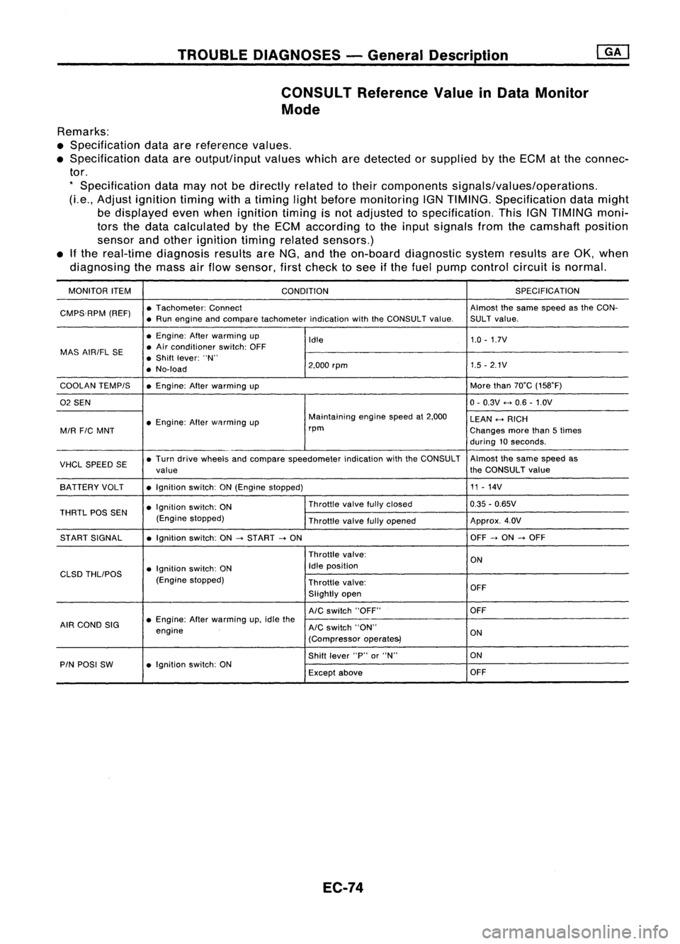
TROUBLEDIAGNOSES -General Description
CONSULT ReferenceValueinData Monitor
Mode
Remarks:
• Specification dataarereference values.
• Specification dataareoutput/input valueswhicharedetected orsupplied bythe ECM atthe connec-
tor.
*
Specification datamaynotbedirectly relatedtotheir components signals/values/operations.
(Le., Adjust ignition timingwithatiming lightbefore monitoring IGNTIMING. Specification datamight
be displayed evenwhen ignition timingisnot adjusted tospecification. ThisIGNTIMING moni-
tors thedata calculated bythe ECM according tothe input signals fromthecamshaft position
sensor andother ignition timingrelated sensors.)
• Ifthe real-time diagnosis resultsareNG, and theon-board diagnostic systemresultsareOK, when
diagnosing themass airflow sensor, firstcheck tosee ifthe fuel pump control circuitisnormal.
MONITOR ITEM
CONDITION SPEC
IFICA TION
CMPS.RPM (REF)•
Tachometer: Connect Almostthesame speed asthe CON-
• Run engine andcompare tachometer indicationwiththeCONSULT value.SULT value.
• Engine: Afterwarming up
Idle 1.0
-1.7V
MAS AIRIFL SE •
Air conditioner switch:OFF
• Shift lever: "N"
• No-load 2,000
rpm 1.5
-2.1V
COOLAN TEMPIS •Engine: Afterwarming up More
than70°C (158°F)
02 SEN 0-
0.3V
<-+
0.6 -1.0V
• Engine: Afterwflrming up Maintaining
enginespeedat2,000
LEAN
<-+
RICH
MIR
FIC
MNT rpm
Changesmorethan5times
during 10seconds .
VHCL SPEED SE•
Turn drive wheels andcompare speedometer indicationwiththeCONSULT Almost
thesame speed as
value the
CONSULT value
SA TTERY VOLT •Ignition switch:ON(Engine stopped) 11
-14V
• Ignition switch:ON Throttle
valvefullyclosed 0.35
-0.65V
THRTL POSSEN
(Enginestopped)
Throttlevalvefullyopened Approx.
4.0V
ST ART SIGNAL •Ignition switch:ON
-->
START
-->
ON OFF
-->
ON
-->
OFF
Throttle valve:
ON
• Ignition switch:ON Idle
position
CLSD THLIPOS
(Enginestopped)
Throttlevalve:
OFF
Slightly open
AIC
switch "OFF" OFF
AIR COND SIG •
Engine: Afterwarming up,idle the
engine
AIC
switch "ON"
ON
(Compressor operate&)
Shift lever "P"or"N" ON
PIN POSI SW •Ignition switch:ON
Exceptabove OFF
EC-74
Page 794 of 1701
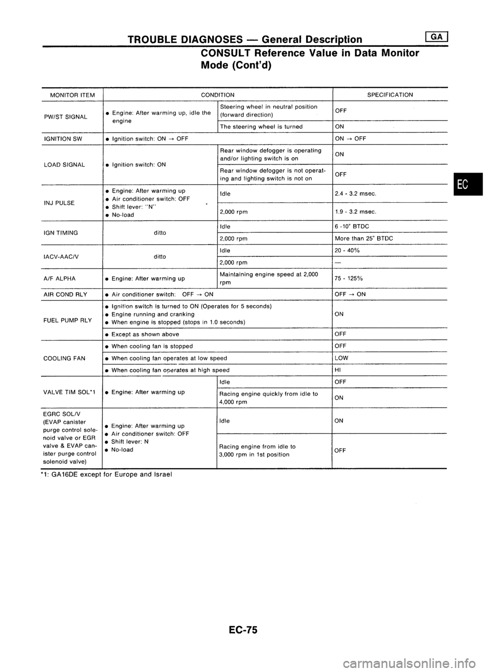
TROUBLEDIAGNOSES -General Description @KJ
CONSULT Reference ValueinData Monitor
Mode (Cont'd)
MONITOR ITEM CONDITION
SPECIFICATION
Steering wheelinneutral position
OFF
PW/ST SIGNAL •
Engine: Afterwarming up.idle the
(forward direction)
engine Thesteering wheelisturned ON
IGNITION SW •
Ignition switch:ON
-->
OFF ON
-->
OFF
Rear window defogger isoperating
ON
and/or lighting switchison
LOAD SIGNAL •
Ignition switch:ON
Rearwindow defogger isnot operat-
OFF
ing and lighting switchisnot on
• Engine: Afterwarming up
Idle 2.4
-3.2 msec.
INJ PULSE •
Air conditioner switch:OFF
• Shift lever: "N"
.
• No-load 2.000
rpm 1.9
-3.2 msec.
Idle 6
_10' BTDC
IGN TIMING ditto
2.000rpm More
than25'BTDC
Idle 20-40%
IACV-AACIV ditto
2.000rpm
-
A/F ALPHA •
Engine: Afterwarming up Maintaining
enginespeedat2.000
75-125%
rpm
AIR COND RLY •
Air conditioner switch:OFF
-->
ON OFF
-->
ON
• Ignition switchisturned toON (Operates for5seconds)
• Engine running andcranking ON
FUEL PUMP RLY
•When engine isstopped (stopsin1.0 seconds)
• Except asshown above OFF
• When cooling fanisstopped OFF
COOLING FAN •
When cooling fanoperates atlow speed LOW
• When cooling fano!Jerates athigh speed HI
Idle OFF
VALVE TIMSOL'1 •Engine: Afterwarming up
Racingenginequickly fromidleto
4.000 rpm ON
EGRC SOLIV
(EVAP canister Idle
ON
purge control sole-•
Engine: Afterwarming up
• Air conditioner switch:OFF
noid valve orEGR
•Shift lever: N
valve
&
EVAP can-
•No-load Racing
enginefromidleto
ister purge control
3.000rpmin1st position OFF
solenoid valve)
*1: GA16DE exceptforEurope andIsrael
EC-75
•
Page 795 of 1701
TROUBLEDIAGNOSES -General Descrip_ti_o_n
I_G_A_'
Major Sensor Reference GraphinData Monitor
Mode
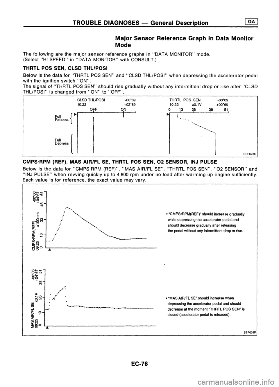
The following arethemajor sensor reference graphsin"DATA MONITOR" mode.
(Select "HISPEED" in"DATA MONITOR" withCONSULT.)
THRTL POSSEN, CLSD THLIPOSI
Below isthe data for"THRTL
pas
SEN" and"CLSD THLIPOSI" whendepressing theaccelerator pedal
with theignition switch"ON".
The signal of"THRTL
pas
SEN" should risegradually withoutanyintermittent droporrise after "CLSD
THLIPOSI" ischanged from"ON" to"OFF".
Full {~
Release
Full {
Depress CLSD
THUPOSI
10:22
OFF
-00"09
+02"69
ON
I
THRTL
POSSEN
10:22 XO.1V
o
13 26 38
~ \
'
..
-00'09
+02'69
51,
SEF673Q
CMPS,RPM (REF),MASAIR/FL SE,THRTL POSSEN, 02SENSOR, INJPULSE
Below isthe data for"CMPS.RPM (REF)","MASAIR/FL SE","THRTL
pas
SEN", "02SENSOR" and
"'NJ PULSE" whenrevving quicklyupto
4,800
rpmunder noload after warming upengine sufficiently.
Each value isfor reference, theexact value mayvary.
:
..
./
.•.•.....•.
,
........... .........
.................................... _
.......
__._
....
E
0-
C5
C\J -
LL~C?
wX
a:
~
a..
co_
a: ...
ci>
1l) .,_,.
a..C\J
;:a"
(.)~o
L.-r-... ------------------
o
"CMPSoRPM(REF)" shouldincrease gradually
while depressing theaccelerator pedaland
should decrease graduallyafterreleasing
the pedal without anyintermittent droporrise.
CO" ...
OCOIt)
gg
, +
CD-
C')
o"MAS AIRIFL SE"should increase when
depressing theaccelerator pedalandshould
decrease atthe moment "THRTLPOSSENu is
closed (accelerator pedalisreleased).
,..
.... -..._••,. •••• \•••• ,.. _ ...... ~ .._ ..._- ......"¥'.,. ..."""""' ..._.... _.._ ... _..- .... _.
...
/
....
.':
>
... co
~C\J
W
C/)
-J ....'
~ ~-
C/)C\J
< ..
.., 0)0
L.r--------------------
"",,0 ...
SEF059P
EC-76
Page 796 of 1701
TROUBLEDIAGNOSES -General Description
Major Sensor Reference Graphin
Mode (Cont'd)
mJ
Data Monitor
cD
....
-
0
cD
ll)
0
~
9
0
+
co
,.
.....
M
>
•
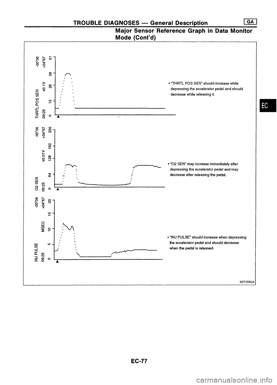
"THRTL pasSEN" should increase while
~
re
depressingtheaccelerator pedelandshould
z
w decreasewhilereleasing it.
en
en
M
•
0
0..
-'
-'
b:
ll)
C\l
:r:
a;
0
A
t-
o
cD
....
cD
0
cD
ll)
b
~
C\l
9
0
+
C\l
C1l
-
>
<3
IX)
ci
C\l
><
.~. ._----•
''02 SEN" mayincrease immediately after
-
-
-
-
depressing theaccelerator pedelandmay
v
decreaseafterreleasing thepedal.
cD
z
w
--
en
ll)
-
.......
C\l C\l
0
a;
0
A
0
cD
....
0
cD
0
b
~
C\l
9
0
+
ll)
u
:~.
w
en
0
:!
-
•"INJ PULSE" shouldincrease whendepressing
w
ll)
the
accelerator pedalandshould decrease
en
whenthepedal isreleased.
-'
j
~---
::>
a.
ll)
'.
I
."""\
C\l
\
..,
a;
0
z
0
A
SEF259QA
EC-77
Page 797 of 1701
TROUBLEDIAGNOSES -General Description
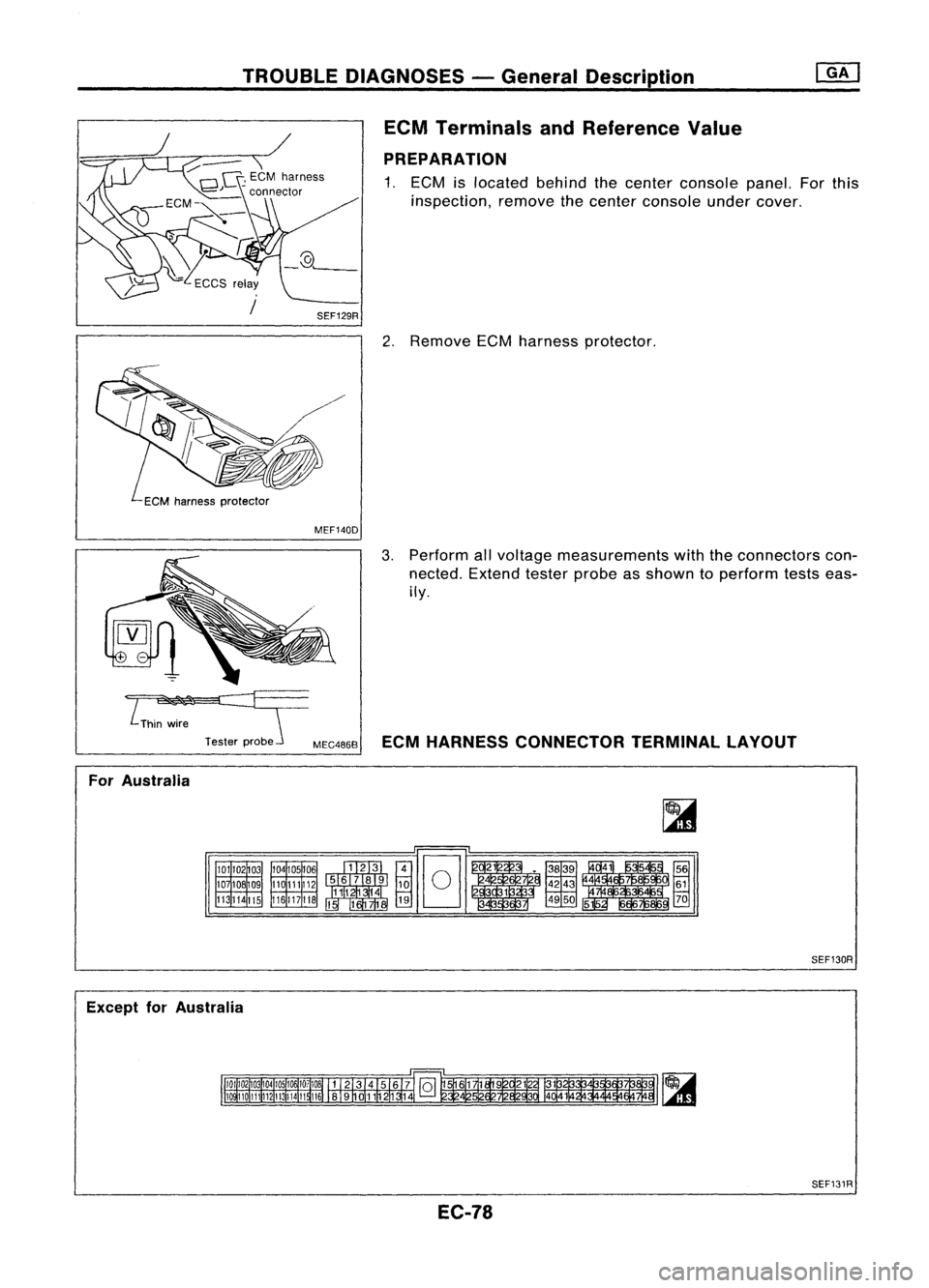
ECM Terminals andReference Value
PREPARATION
1. ECM islocated behindthecenter console panel.Forthis
inspection, removethecenter console undercover.
2. Remove ECMharness protector.
MEF140D
3.Perform allvoltage measurements withtheconnectors con-
nected. Extendtesterprobeasshown toperform testseas-
ily.
~~
Testerprobe
MEC4868ECMHARNESS CONNECTOR TERMINALLAYOUT
For Australia
101102
03
107
lOB
09
113 114
115
Except forAustralia
104
105106
110 111112
116 117
lIB
~
~1~9
@]8
1 .~~~~.41
i
i5~
3 1 4950 70
51
SEF130R
SEF131R
EC-78
Page 798 of 1701
![NISSAN ALMERA N15 1995 Service Manual TROUBLEDIAGNOSES -General Description @K]
ECM Terminals andReference Value(Conl'd)
ECM INSPECTION TABLE-GA16DE forAustralia
Specification dataarereference valuesandaremeasured betweeneachterminal NISSAN ALMERA N15 1995 Service Manual TROUBLEDIAGNOSES -General Description @K]
ECM Terminals andReference Value(Conl'd)
ECM INSPECTION TABLE-GA16DE forAustralia
Specification dataarereference valuesandaremeasured betweeneachterminal](/img/5/57349/w960_57349-797.png)
TROUBLEDIAGNOSES -General Description @K]
ECM Terminals andReference Value(Conl'd)
ECM INSPECTION TABLE-GA16DE forAustralia
Specification dataarereference valuesandaremeasured betweeneachterminal and
@
(ECCS ground).
TER- WIRE
MINAL ITEM
CONDITION DATA
NO. COLOR
[Efl9ineisrunning.
I
0.3-0.6V
L Idle speed
1
WIB
Ignitionsignal
I
Engine isrunning.
I
L Engine speedis2,000 rpm. Approximately
0.9V
2
GYIR
Ignition
check IEngine
isrunning.
I
Approximately12V
L Idle speed
3 LIB Tachometer [Engine
isrunning.
I
Approximately0.9V
L Idle speed
IEngine isrunning.
I
Ilgnition switch"OFF'.'
0-1V
4
WIG
ECCS
relay(Self-shut- L
For afew seconds afterturning ignition
off) switch
"OFF"
Ilgnition switch"OFF"
I
BATTERYVOLTAGE
L Afew seconds passedafterturning ignition
(11-14V)
switch "OFF"
Ilgnition switch"ON"
I
L For 5seconds afterturning ignition switch
0.07-0.20V
"ON"
8
BIP Fuel
pump relay I
Engine isrunning.
I
Ilgnition switch"ON"
I
BATTERYVOLTAGE
L More than5seconds afterturning ignition
(11-14V)
switch "ON"
10
BIW
ECCSground IEngine
isrunning.
I
Engineground
L Idle speed
IEngine isrunning.
I
BATTERYVOLTAGE
Cooling fanrelay ~Cooling fanisnot operating.
(11-14V).
13 LG
(Highspeed: For
AIT
Cooling
fanisoperating atlow speed.
models)
I
Engine isrunning.
I
L Cooling fanisoperating athigh speed. Approximately
OV
IEngine isrunning.
I
BATTERYVOLTAGE
Cooling fanrelay L
Cooling fanisnot operating. (11-14V)
14 LGIR
(Lowspeed)
I
Engine isrunning.
I
L_
Cooling fanisoperating. 0.07
-0.30V
I
Engine isrunning.
I
L Both
AIC
switch andblower switchare 0.08
-0.2V
15
Y
Air
conditioner relay "ON".
IEngine isrunning.
I
BATTERYVOLTAGE
LAIC switchis"OFF". (11
-14V)
EC-79
•
Page 799 of 1701
TROUBLEDIAGNOSES -General Description ~
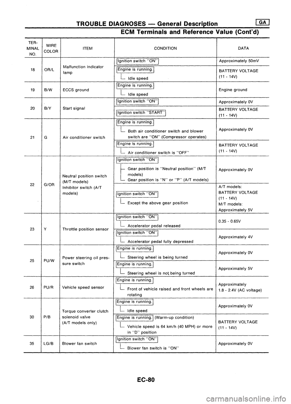
ECM Terminals andReference Value(Cont'd)
TER- WIRE
MINAl ITEM CONDITION DATA
NO. COLOR
/'gnitionswitch"ON'" Approximately
50mV
18 OR/l Malfunction
indicator
I
Engine isrunning.
I
lamp BATTERY
VOLTAGE
L
Idle speed (11.14V)
19 BIW ECCS
ground
I
Engine isrunning.
I
Engineground
L
Idle speed
I'gnition switch"ON"
I
ApproximatelyOV
20 BIY
Startsignal
BATTERYVOLTAGE
I'gnition switch"5TART"
I
(11-14V)
I
Engine isrunning.
I
L
Both airconditioner switchandblower Approximately
OV
21 G Airconditioner switch switch
are"ON" (Compressor operates)
IEngine isrunning.
I
BATTERYVOLTAGE
L
Airconditioner switchis"OFF" (11
-14V)
I'gnition switch"ON'"
t
Ge.,
po,"'on "
"Ne"".1
po,ltlon"
(MIT
Approximately OV
Neutral position switch models)
(M/T
models) Gear
position is"N" or"P"
(A/T
models)
22
G/OR
Inhibitorswitch
(A/T AIT
models:
models) llgnitionswitch"ON'" BATTERY
VOLTAGE
L
Except theabove gearposition (11
-14V)
M/T
models:
Approximately 5V
Ilgnition switch"ON"
I
0.35-0.65V
L
Accelerator pedalreleased
23 Y Throttleposition sensor
!'gnitionswitch"ON"
I
L
Accelerator pedalfullydepressed Approximately
4V
/Engine isrunning.1
ApproximatelyOV
25 Pu/W Power
steering oilpres-
L
Steering wheelisbeing turned
sure switch
IEngineisrunning.1
L
Steering wheelisnot being turned Approximately
5V
I
Engine isrunning.
I
Approximately
26 PUIR Vehiclespeedsensor
L
Front ofvehicle raisedandfront wheels are
1.8-2.4V (ACvoltage)
rotating
I
Engine isrunning.
I
ApproximatelyOV
Torque converter clutch
L
Idle speed
30 PIB
solenoidvalve
I
Engine isrunning.
I
(Warm-up condition)
(A/T
models only)
L
Vehicle speedis64 km/h (40MPH) ormore BATTERY
VOLTAGE
(11-14V)
in "D" position
35 lG/B Blower
fanswitch I,gnition
switch"ON",
ApproximatelyOV
L
Blower fanswitch is"ON"
EC-80
Page 800 of 1701
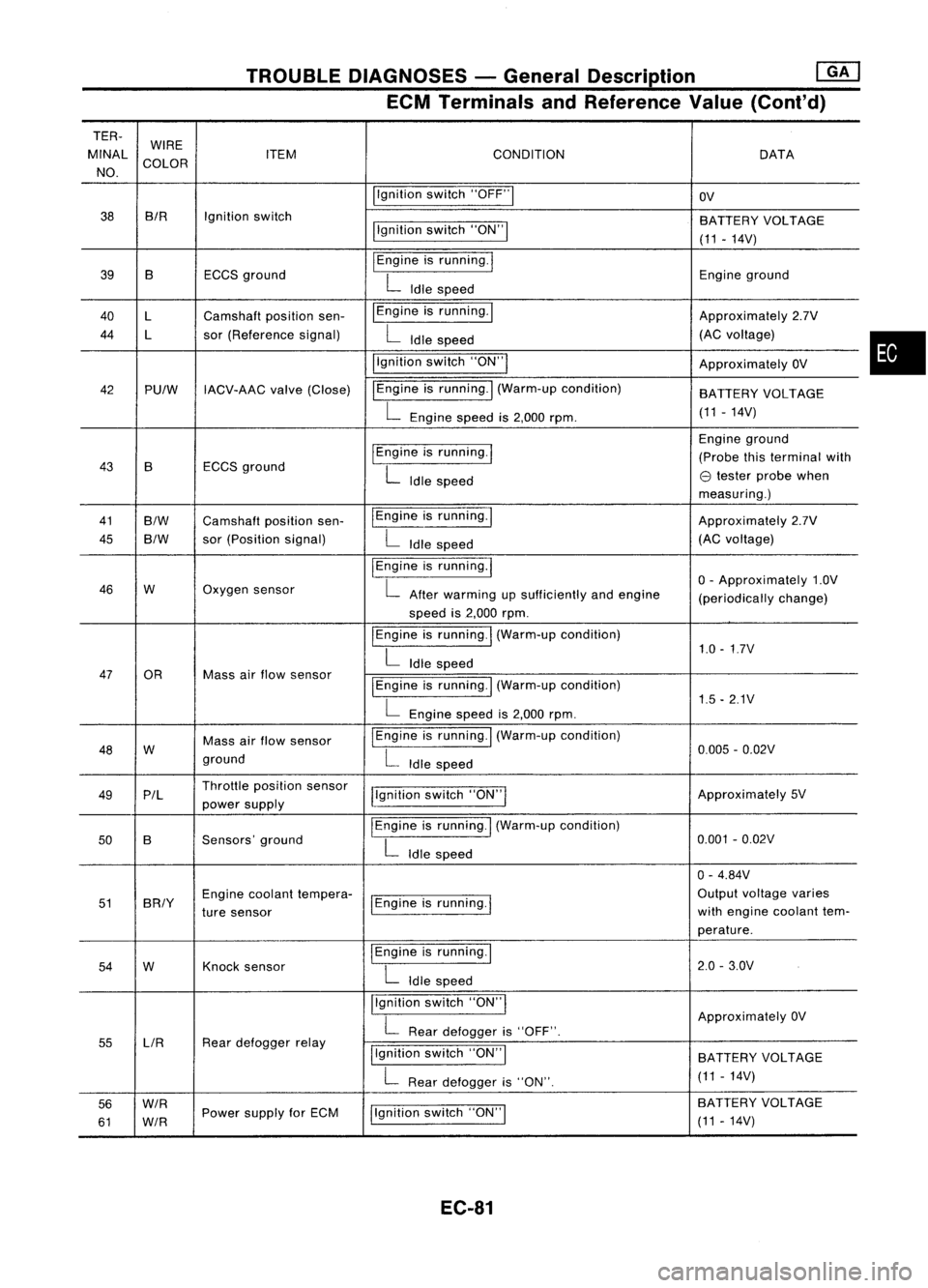
TROUBLEDIAGNOSES -General Description ~
ECM Terminals andReference Value(Cont'd)
TER-
MINAL WIRE
CONDITION
ITEM DATA
NO. COLOR
Ilgnitionswitch"OFF"1
OV
38 BIR
Ignitionswitch
BATTERYVOLTAGE
llgnition switch"ON"!
(11-14V)
39 B ECCSground
I
Engine isrunning.
I
Engineground
L
Idle speed
40 l Camshaft positionsen- I
Engine isrunning. I
Approximately2.7V
44 l sor(Reference signal)
L
Idle speed (AC
voltage)
i'gnition switch"ON'"
ApproximatelyOV
42 PUlW IACV-AAC valve(Close) IEngine
isrunning.
I
(Warm-up condition)
BATTERYVOLTAGE
L
Engine speedis2,000 rpm. (11
-14V)
I
Engine isrunning.
I
Engine
ground
43 B ECCS
ground (Probe
thisterminal with
L
Idle speed
e
tester probe when
measuring.)
41
B/W
Camshaft positionsen- IEngine
isrunning.1
Approximately2.7V
45
B/W
sor
(Position signal)
L
Idle speed (AC
voltage)
I
Engine isrunning.
I
o-
Approximately 1.0V
46 W Oxygen
sensor
L
After warming upsufficiently andengine
(periodicallychange)
speed is2,000 rpm.
I
Engine isrunning.
I
(Warm-up condition)
1.0-1.7V
L
Idle speed
47 OR Massairflow sensor
I
Engine isrunning.! (Warm-up condition)
L
Engine speedis2,000 rpm. 1.5
-2.1V
48 W Mass
airflow sensor
I
Engine isrunning. I(Warm-up condition)
0.005-0.02V
ground
L
Idle speed
49 P/l Throttle
position sensor
j!gnitionswitch"ON"I Approximately
5V
power supply
50 B Sensors'
ground
I
Engine isrunning.
I
(Warm-up condition)
0.001-0.02V
L
Idle speed
0-4.84V
51 BRIY Engine
coolant tempera-
1Engine isrunning.
I
Output
voltage varies
ture sensor with
engine coolant tem-
perature.
54 W Knock
sensor
I
Engine isrunning.!
2.0-3.0V
L
Idle speed
Ilgnition switch"ON'"
ApproximatelyOV
L
Rear defogger is"OFF".
55 LlR Rear
defogger relay
Ilgnitionswitch"ON"I
BATTERY VOLTAGE
L
Rear defogger is"ON". (11
-14V)
56
W/R
Ilgnitionswitch"ON"I BA
TTERY VOLTAGE
61
W/R
Power
supply forECM
(11-14V)
EC-81
•