NISSAN ALMERA N15 1995 Service Manual
Manufacturer: NISSAN, Model Year: 1995, Model line: ALMERA N15, Model: NISSAN ALMERA N15 1995Pages: 1701, PDF Size: 82.27 MB
Page 811 of 1701
![NISSAN ALMERA N15 1995 Service Manual
(i]
1
CHECK HARNESS CONTINUITY NG
Repair harness orcon-
BETWEEN ECCSRELAY ANDECM
--..
nectors.
1. Disconnect ECMharness connector.
2. Disconnect ECCSrelay.
3. Check harness continuity between
ECM NISSAN ALMERA N15 1995 Service Manual
(i]
1
CHECK HARNESS CONTINUITY NG
Repair harness orcon-
BETWEEN ECCSRELAY ANDECM
--..
nectors.
1. Disconnect ECMharness connector.
2. Disconnect ECCSrelay.
3. Check harness continuity between
ECM](/img/5/57349/w960_57349-810.png)
(i]
1
CHECK HARNESS CONTINUITY NG
Repair harness orcon-
BETWEEN ECCSRELAY ANDECM
--..
nectors.
1. Disconnect ECMharness connector.
2. Disconnect ECCSrelay.
3. Check harness continuity between
ECM terminals
@,@,
or
@,
@
and terminal
@.
Continuity shouldexist.
If OK, check harness forshort.
Checkthefollowing .
• Harness connectors
OK ~''fflDr~,
M41
or
F4,M71
• Harness connectors
Ii
~,@IDorQD,
M78
CHECK VOLTAGE BETWEEN ECCS NG
•
Harness connectors
RELA YAND GROUND.
---+-
@,@ID
1. Check voltage between terminals G), •
Joint connector
@
and ground withCONSULTor
@
tester. •
Harness foropen or
Voltage: Batteryvoltage short
between ECCS
relay andbattery
OK If
NG, repair harness or
connectors.
Ii
CHECK OUTPUT SIGNALCIRCUIT. NG
Repair harness orcon-
1. Check harness continuity between ~
nectors.
ECM terminal
@
and terminal
@.
ContinUity shouldexist.
If OK, check harness forshort.
[I
OK
~
CHECK
ECCSRELAY. Replace
ECCSrelay.
1. Apply 12Vdirect current between
relay terminals G)and
@.
2. Check continuity betweenrelayter-
minals
@
and
@.
12V (G) -
@)
applied:
Continuity exists.
No voltage applied:
No continuity
OK
AEC6B4
SEF129R
TROUBLE
DIAGNOSIS FORPOWER SUPPLY
ffiJ
Main Power Supply andGround Circuit(Cont'd)
@
SEF023M EC-92
Page 812 of 1701
TROUBLEDIAGNOSIS FORPOWER SUPPLY
em
Main Power Supply andGround Circuit(Cont'd)
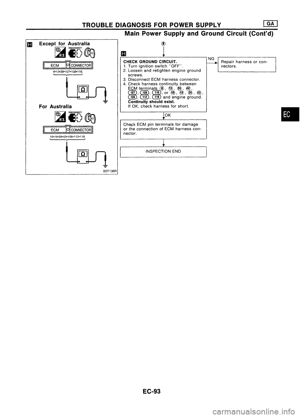
Except forAustralia
~i5~
II
ECM
B'
CONNECTOR
II
6-13-39-107-108-116
.
,
For Australia
~i5@a
II
ECM
B'
CONNECTOR
II
10-19-39-43-106-112-118
.
,
SEF136R CHECK
GROUND CIRCUIT.
1. Turn ignition switch"OFF".
2. Loosen andretighten engineground
screws.
3. Disconnect ECMharness connector.
4. Check harness continuity between
ECM terminals
@,
@,
@,@,
Gill, Gill,Gill,
or
@),
@,
@,
@,
GID, GID,
@
andengine ground.
Continuity shouldexist.
If OK, check harness forshort.
OK
Che~k ECMpinterminals fordamage
or the connection ofECM harness con-
nector.
INSPECTION END
EC-93
NG
Repair harness orcon-
nectors.
•
Page 813 of 1701
TROUBLEDIAGNOSIS FORDTC11
Light emitting
diode
Wave
forming circuit
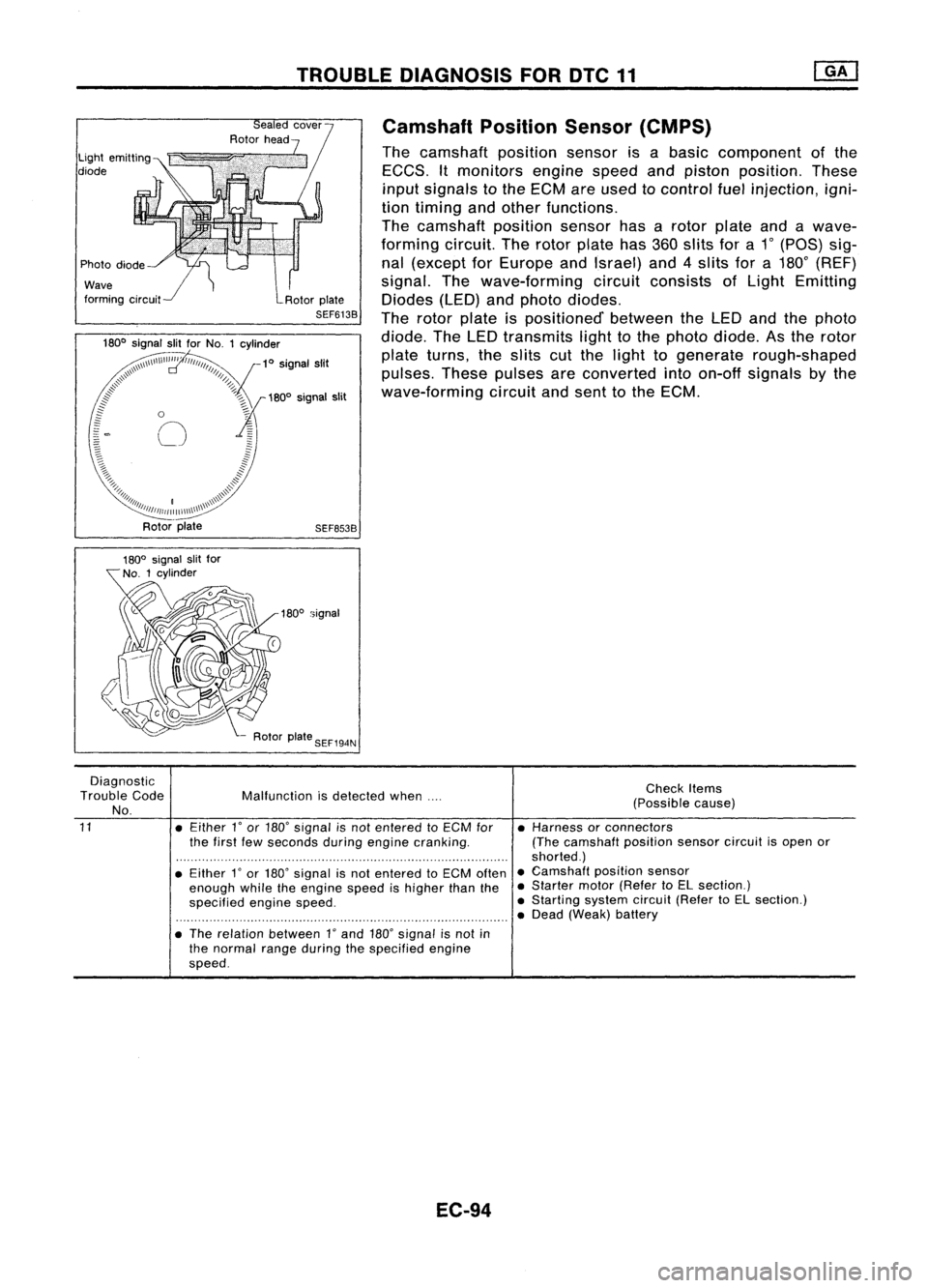
Camshaft
PositionSensor(CMPS)
The camshaft positionsensorisabasic component ofthe
EGGS. Itmonitors enginespeedandpiston position. These
input signals tothe EGM areused tocontrol fuelinjection, igni-
tion timing andother functions.
The camshaft positionsensorhasarotor plate andawave-
forming circuit.Therotor plate has360slits fora1
0
(paS) sig-
nal (except forEurope andIsrael) and4slits fora180
0
(REF)
signal. Thewave-forming circuitconsists ofLight Emitting
Diodes (LED)andphoto diodes.
The rotor plate ispositioned' betweentheLED andthephoto
diode. TheLED transmits lighttothe photo diode. Asthe rotor
plate turns, theslits cutthe light togenerate rough-shaped
pulses. Thesepulses areconverted intoon-off signals bythe
wave-forming circuitandsent tothe EGM.
SEF653B
180
0
signal
Diagnostic
Trouble Code
No.
11
Malfunction
isdetected when....
• Either
l'
or 180' signal isnot entered toECM for
the first fewseconds duringengine cranking.
• Either
l'
or 180' signal isnot entered toECM often
enough whiletheengine speedishigher thanthe
specified enginespeed.
• The relation between
l'
and 180'signal isnot in
the normal rangeduring thespecified engine
speed.
EC-94
Check
Items
(Possible cause)
• Harness orconnectors
(The camshaft positionsensorcircuitisopen or
shorted.)
• Camshaft positionsensor
• Starter motor(Refer toEL section.)
• Starting systemcircuit(RefertoEL section.)
• Dead (Weak) battery
Page 814 of 1701
TROUBLEDIAGNOSIS FORDTC11 @KJ
Camshaft PositionSensor(CMPS) (Cont'd)
DIAGNOSTIC TROUBLECODECONFIRMATION
PROCEDURE
fiii\
1)Turn ignition switch"ON"andselect "DATA
\JV
MONITOR" modewithCONSULT.
2) Crank engine foratleast 2seconds.
---------- OR-----------
~ 1)Crank engine foratleast 2seconds.
~ 2)Turn ignition switch"OFF", waitforatleast 5seconds
and then turn"ON".
3) Perform "Diagnostic TestMode II"(Self-diagnostic
results) withECM.
EC-95
•
Page 815 of 1701
![NISSAN ALMERA N15 1995 Service Manual TROUBLEDIAGNOSIS FORDTC11
[]KJ
Camshaft PositionSensor(CMPS) (Cont'd)
For Europe andIsrael
EC-CMPS-01
*1:
@
40
@30
*2: @31
@22
(b):
LHDmodels
@:
RHOmodels
@:
ForEurope
@:
ForIsrae NISSAN ALMERA N15 1995 Service Manual TROUBLEDIAGNOSIS FORDTC11
[]KJ
Camshaft PositionSensor(CMPS) (Cont'd)
For Europe andIsrael
EC-CMPS-01
*1:
@
40
@30
*2: @31
@22
(b):
LHDmodels
@:
RHOmodels
@:
ForEurope
@:
ForIsrae](/img/5/57349/w960_57349-814.png)
TROUBLEDIAGNOSIS FORDTC11
[]KJ
Camshaft PositionSensor(CMPS) (Cont'd)
For Europe andIsrael
EC-CMPS-01
*1:
@
40
@30
*2: @31
@22
(b):
LHDmodels
@:
RHOmodels
@:
ForEurope
@:
ForIsrae 1
t
•
W!R
~
~ ~
B L
DISTRIBUTOR
(CAMSHAFT
POSITION
SENSOR)
m
Detectable
line
for OTC
Non-detectable line forDTC
(
:.
I I
I I
JOINT
II
CONNECTOR-6 ::
@
II
.--rq~==~
~=~.
J
I "
11 ~~
B B B REFREF
t.J
1
ffi) ffi)
Refer
to
7.5A EL-POWER. JUNCTIONBOX
[11] No.2(JOINT
CONNECTORS)
W!L ~
<:MID
6-
~-==_ -==~~
W!L
-----
----------.....:(B)-O
~ <:MID
I
W!L@
4n
W!L
@
I
rT
W!L W!L
I[XI
ECCS
~ RELAY
@
lbjJJ~
W!R WIG
I
...
_--.
... 1
ri-i
W!R W!RW!RWIG
~ff17n~m
CRTN VBVBSSOFF ECM
(ECCSCONTROL
MODULE)
em
-:
-:
~cw
ITIIJ:IITIIill
GY
~'I'I~@
3456 W
A@
T
L
Refer
tolast page
(Foldout page).
HEC028
EC-96
Page 816 of 1701
TROUBLEDIAGNOSIS FOROTC11
mJ
Camshaft PositionSensor(CMPS) (Cont'd)
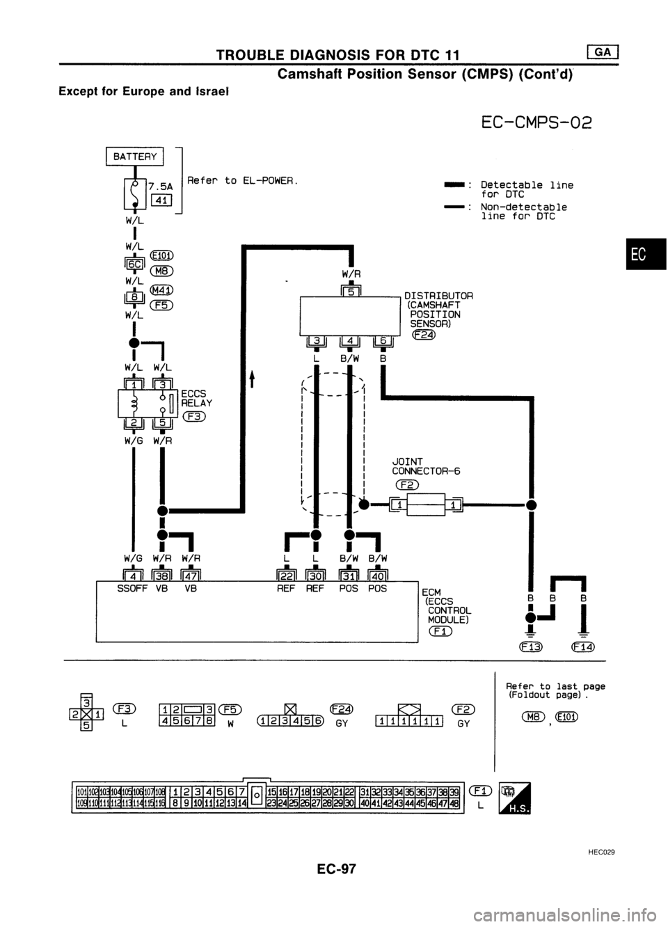
Except forEurope andIsrael
EC-CMPS-02
•
II
8 B 8
t.J
1
(l=J3)
m
Detectable
line
for DTC
Non-detectable line forDTC
-:
-:
ECM (ECCS
CONTROL
MODULE)
(ill
DISTRIBUTOR
(CAMSHAFT
POSITION
SENSOR)
JOINT
CONNECTOR-6
I
W/R
m
---
~~~
L B/W B
(
,
I' ...
1
I I
I I
I I
I I
I I
I I
I I
I I
I I
I I
I I
I
I
ern
l'" --- ....
--iCY=_
-=~-- •
T,
B/W B/W
If31iI
I
4.0
I
POS POS
iT
L L
12~1 ';01
REF REF
t
BATTERY
]
7.5A RefertoEL-POWER.
ffi]
W!L
I
W/L
tE7iIT\
1FsB1~
~CBID
W!L
I~IQMD
@)
W/L
I
Ti
W!L W!L
IT]I
ECCS
~ RELAY
1bf=!J~(U)
WIG W/R
I
.
--_
..
I
T,
WIG W/R W/R
mmIT17TI
SSOFF VBVB
~' I'~
@) ~
4 56 78 W (1121341516) GY
~ern
[[[[OOJOJOJD
GY
Refer
tolast page
(Foldout page).
HEC029
EC-97
Page 817 of 1701
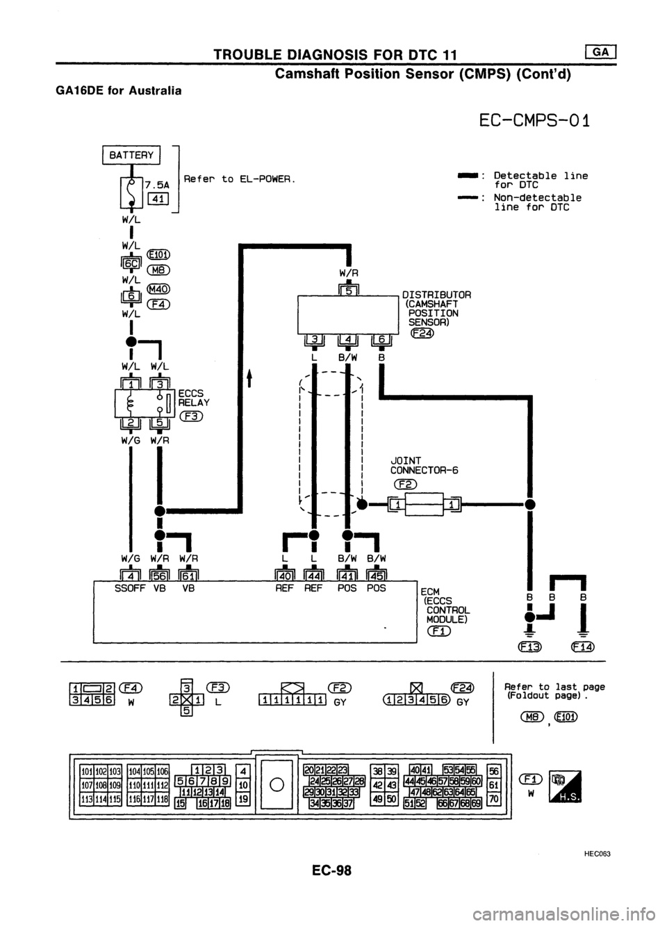
TROUBLEDIAGNOSIS FORDTC11 rn:J
Camshaft PositionSensor(CMPS) (Cont'd)
GA16DE forAustralia
EC-CMPS-01
Refer toEL-POWER. -:
Detectable line
for DTC
-: Non-detectable
line forDTC
t
....,
B B B
t....
1
(ffi)
m
ECM
(ECCS
CONTROL
MODULE)
em
DISTRIBUTOR
(CAMSHAFT
POSITION
SENSOR)
m
JOINT
CONNECTOR-6
---
1hp~lbi=!J
L B/W B
(
'"
"
.-1
r---
I
I
I
I
I
I
I
I
I
I
I
l@
~.- --- .-.~=_
~=m-- •
"
B/W
B/W
~ 114'51
POS POS
r'
L
L
14.0
I
n14n
REF REF
W/L
I
W/L
IE7iU\
r=::b'!JQ.!.,
I~I@
w!L
1m, ~
=r
ern
W/L
I
T-,
W!L W/L
I~~I
ECCS
~ RELAY
U:::i=JIlbiJcrn
WIG W/R
I
. --_
..
I
"
WIG
W/RW/R
fi1=il~~
SSOFF VBVB
fIJ'
I
'fi)
ern
3456 W
+
crn
2 1L
5
~@
[I[illlI[!ll]
GY
Refer
tolast page
(Foldout page).
101 102 103
107
lOB
109
113 114115 104
105106
110 111
112
116
117
118
HEC063
EC-98
Page 818 of 1701
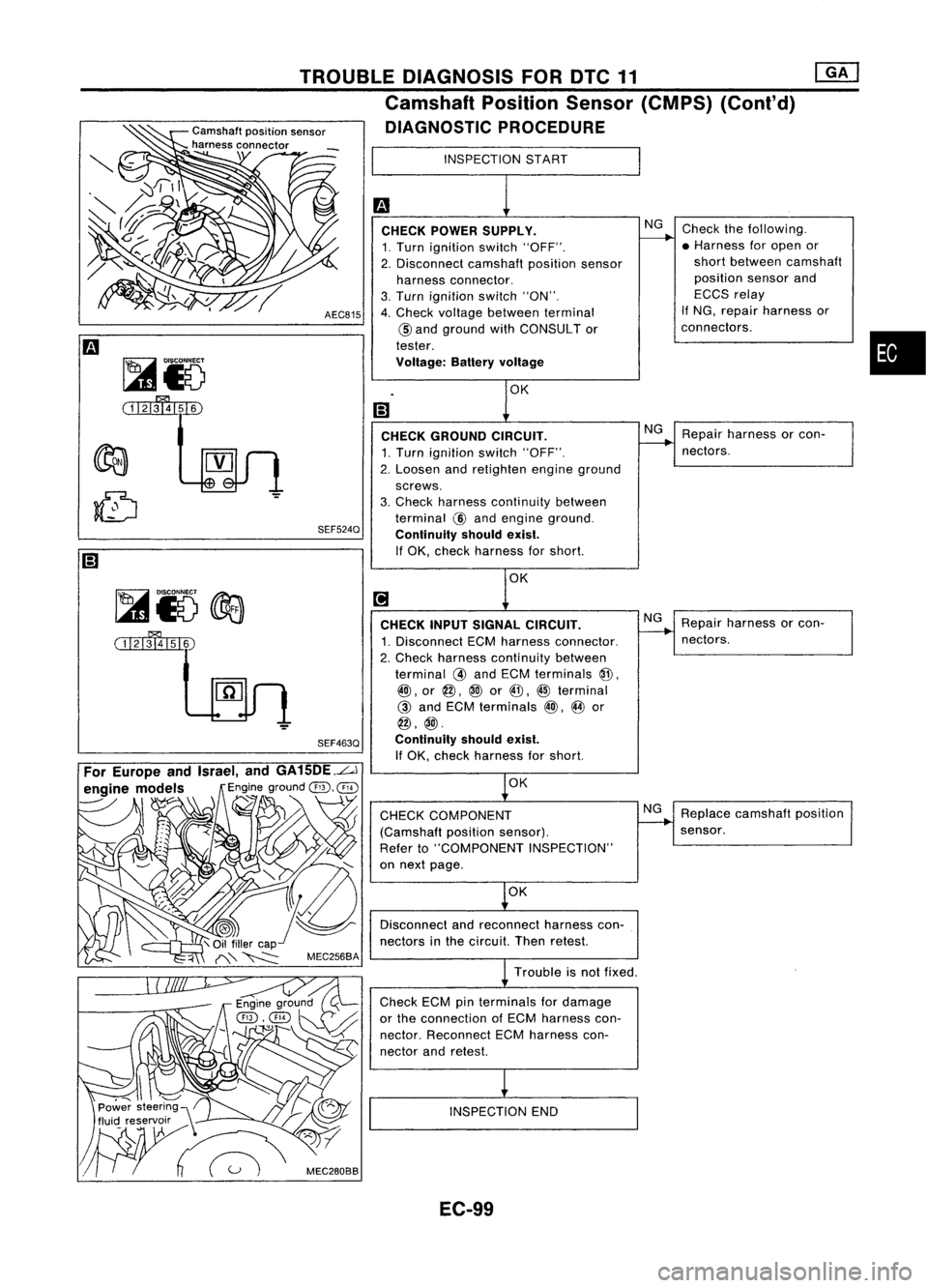
•
Repair harness orcon-
nectors.
Check
thefollowing.
• Harness foropen or
short between camshaft
position sensorand
ECCS relay
If NG, repair harness or
connectors .
NG
NG
CHECK
POWER SUPPLY.
1. Turn ignition switch"OFF".
2. Disconnect camshaftpositionsensor
harness connector.
3. Turn ignition switch"ON".
4. Check voltage between terminal
@
and ground withCONSULT or
tester.
Voltage: Batteryvoltage
CHECK GROUND CIRCUIT.
1. Turn ignition switch"OFF".
2. Loosen andretighten engineground
screws.
3. Check harness continuity between
terminal
@
and engine ground.
Continuity shouldexist.
If OK, check harness forshort.
AEC815
SEF524Q
TROUBLE
DIAGNOSIS FORDTC11 ~
Camshaft PositionSensor(CMPS) (Conl'd)
Camshaft positionsensor
DIAGNOSTIC PROCEDURE
harness connector
\ INSPECTIONSTART
Trouble isnot fixed.
~i5
@a
(i1'lmI51~ CHECK
INPUTSIGNAL CIRCUIT.
1. Disconnect ECMharness connector.
2. Check harness continuity between
terminal
@
and ECM terminals
@.
@),
or
@,
@
or
@, @
terminal
@
and ECM terminals
@),
@
or
@,@.
SEF463Q Continuityshouldexist.
If
OK, check harness forshort.
OK
CHECK COMPONENT
(Camshaft positionsensor).
Refer to"COMPONENT INSPECTION"
on next page.
OK
Disconnect andreconnect harnesscon-
nectors inthe circuit. Thenretest.
Check ECMpinterminals fordamage
or the connection ofECM harness con-
nector. Reconnect ECMharness con-
nector andretest.
INSPECTION END
NG
Repair
harness orcon-
nectors.
Replace camshaft position
sensor.
EC-99
Page 819 of 1701
![NISSAN ALMERA N15 1995 Service Manual TROUBLEDIAGNOSIS FORDTC11 @KJ
Camshaft PositionSensor(CMPS) (Cont'd)
@]
~io
~IO
Il
ECM ECONNECroRl1
~JlI0
~29, ~
@,
@:
ForIsrael
@,
@:
ForEurope
~ IDISCO~
l41
V
~io
1=1
=E=CM=:!iE NISSAN ALMERA N15 1995 Service Manual TROUBLEDIAGNOSIS FORDTC11 @KJ
Camshaft PositionSensor(CMPS) (Cont'd)
@]
~io
~IO
Il
ECM ECONNECroRl1
~JlI0
~29, ~
@,
@:
ForIsrael
@,
@:
ForEurope
~ IDISCO~
l41
V
~io
1=1
=E=CM=:!iE](/img/5/57349/w960_57349-818.png)
TROUBLEDIAGNOSIS FORDTC11 @KJ
Camshaft PositionSensor(CMPS) (Cont'd)
@]
~io
~IO
Il
ECM ECONNECroRl1
~JlI0
~29, ~
@,
@:
ForIsrael
@,
@:
ForEurope
~ IDISCO~
l41
V
~io
1=1
=E=CM=:!iE[il=CO=NN=EC=ro=RII
~~TGo[rnID
@,
@,
@,
@ :
Except forAustralia
@,@,@,@ :
For Australia
@a
SEF137R
COMPONENT INSPECTION
Camshaft positionsensor
1. Start engine.
2. Check voltage between camshaft positionsensorterminals
CID,
@
and ground withACrange.
3. IfNG, replace distributor assemblywithcamshaft position
sensor.
4. Remove distributor cap.Visually checksignal platefordam-
age ordust.
After thisinspection, diagnostictroublecodeNo.11might be
displayed withcamshaft positionsensorfunctioning properly.
Erase thestored memory.
AEC689
SEF887K
Terminal
@ :
Except forEurope andIsrael
@:
ForEurope andIsrael
(180.
signal)
@ :
Except forEurope andIsrael
(1.
signal) Voltage
Tester's pointerfluctuates between
5V and OV.
EC-100
Page 820 of 1701
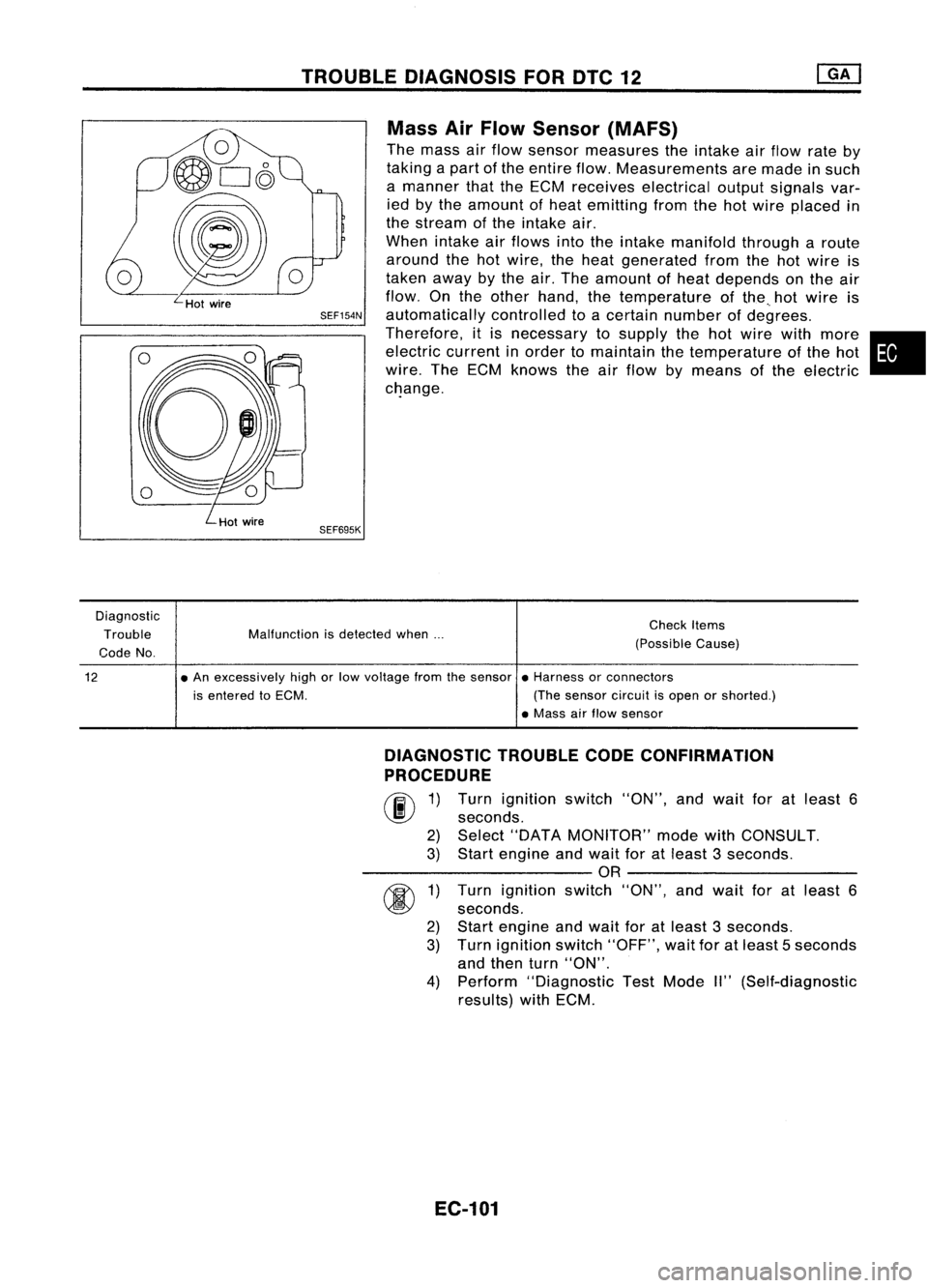
TROUBLEDIAGNOSIS FORDTC12
Mass AirFlow Sensor (MAFS)
The mass airflow sensor measures theintake airflow rateby
taking apart ofthe entire flow.Measurements aremade insuch
a manner thattheECM receives electrical outputsignals var-
ied bythe amount ofheat emitting fromthehotwire placed in
the stream ofthe intake air.
When intake airflows intotheintake manifold througharoute
around thehotwire, theheat generated fromthehotwire is
taken awaybythe air.The amount ofheat depends onthe air
flow. Onthe other hand, thetemperature ofthe ..hot wire is
SEF154N
automatically controlledtoacertain number ofdegrees.
Therefore, itis necessary tosupply thehotwire withmore •
electric currentinorder tomaintain thetemperature ofthe hot
wire. TheECM knows theairflow bymeans ofthe electric
c~ange.
SEF695K
Diagnostic Trouble
Code No. Malfunction
isdetected when... Check
Items
(Possible Cause)
12
•
An excessively highorlow voltage fromthesensor •Harness orconnectors
is entered toECM. (Thesensor circuitisopen orshorted.)
• Mass airflow sensor
DIAGNOSTIC TROUBLECODECONFIRMATION
PROCEDURE
rif\
1)Turn ignition switch"ON",andwait foratleast 6
~ seconds.
2) Select "DATA MONITOR" modewithCONSULT.
3) Start engine andwait foratleast 3seconds.
----------OR ----------
r
~ seconds.
2) Start engine andwait foratleast 3seconds.
3) Turn ignition switch"OFF", waitforatleast 5seconds
and then turn"ON".
4) Perform "Diagnostic TestMode II"(Self-diagnostic
results) withECM.
EC-101