NISSAN ALMERA N16 2001 Electronic Repair Manual
ALMERA N16 2001
NISSAN
NISSAN
https://www.carmanualsonline.info/img/5/57351/w960_57351-0.png
NISSAN ALMERA N16 2001 Electronic Repair Manual
Trending: p0325, Ignition coil, EL-87, manual radio set, steering wheel adjustment, fuse diagram, OBD port
Page 1561 of 2493
Control Valve Assembly
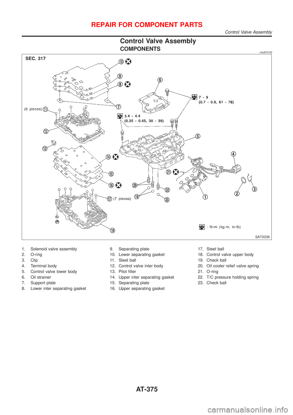
COMPONENTS=NJAT0129
SAT033K
1. Solenoid valve assembly
2. O-ring
3. Clip
4. Terminal body
5. Control valve lower body
6. Oil strainer
7. Support plate
8. Lower inter separating gasket9. Separating plate
10. Lower separating gasket
11. Steel ball
12. Control valve inter body
13. Pilot filter
14. Upper inter separating gasket
15. Separating plate
16. Upper separating gasket17. Steel ball
18. Control valve upper body
19. Check ball
20. Oil cooler relief valve spring
21. O-ring
22. T/C pressure holding spring
23. Check ball
REPAIR FOR COMPONENT PARTS
Control Valve Assembly
AT-375
Page 1562 of 2493
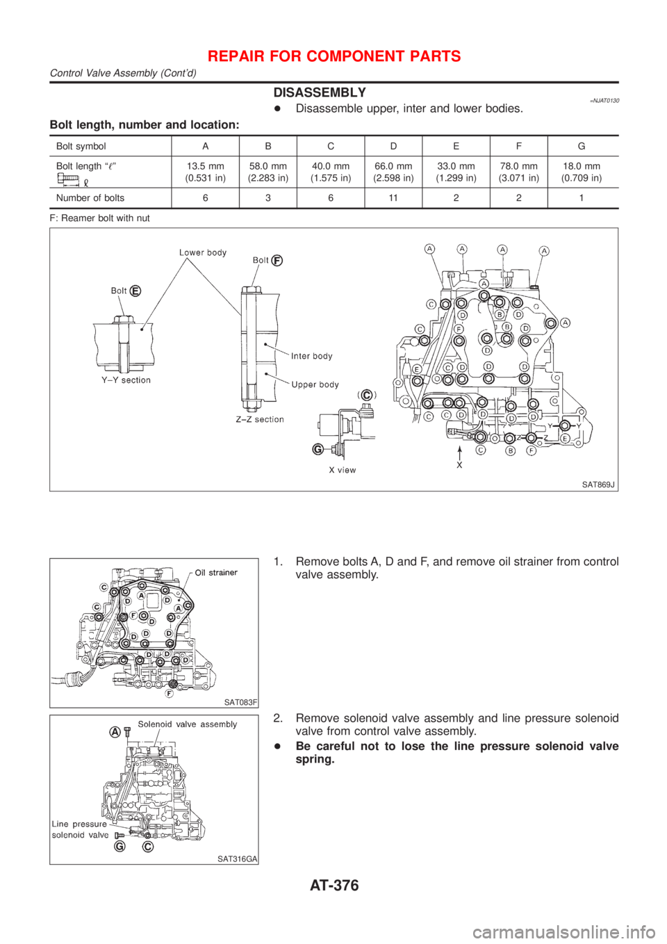
DISASSEMBLY=NJAT0130+Disassemble upper, inter and lower bodies.
Bolt length, number and location:
Bolt symbol A B C D E F G
Bolt length ª!º
13.5 mm
(0.531 in)58.0 mm
(2.283 in)40.0 mm
(1.575 in)66.0 mm
(2.598 in)33.0 mm
(1.299 in)78.0 mm
(3.071 in)18.0 mm
(0.709 in)
Number of bolts 6 3 6 11 2 2 1
F: Reamer bolt with nut
SAT869J
SAT083F
1. Remove bolts A, D and F, and remove oil strainer from control
valve assembly.
SAT316GA
2. Remove solenoid valve assembly and line pressure solenoid
valve from control valve assembly.
+Be careful not to lose the line pressure solenoid valve
spring.
REPAIR FOR COMPONENT PARTS
Control Valve Assembly (Cont'd)
AT-376
Page 1563 of 2493
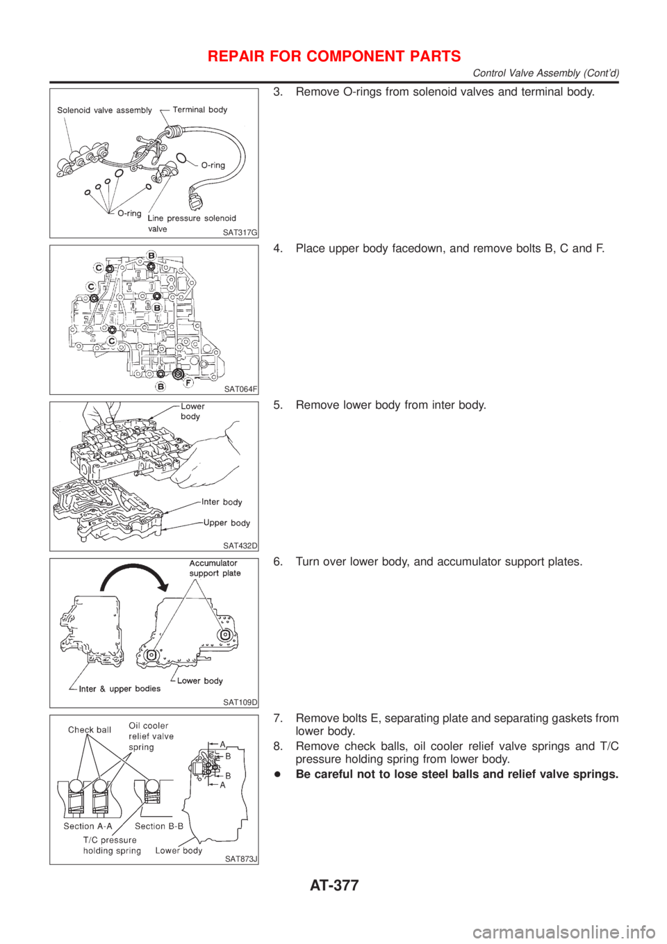
SAT317G
3. Remove O-rings from solenoid valves and terminal body.
SAT064F
4. Place upper body facedown, and remove bolts B, C and F.
SAT432D
5. Remove lower body from inter body.
SAT109D
6. Turn over lower body, and accumulator support plates.
SAT873J
7. Remove bolts E, separating plate and separating gaskets from
lower body.
8. Remove check balls, oil cooler relief valve springs and T/C
pressure holding spring from lower body.
+Be careful not to lose steel balls and relief valve springs.
REPAIR FOR COMPONENT PARTS
Control Valve Assembly (Cont'd)
AT-377
Page 1564 of 2493
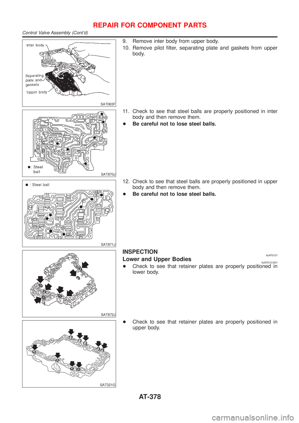
SAT065F
9. Remove inter body from upper body.
10. Remove pilot filter, separating plate and gaskets from upper
body.
SAT870J
11. Check to see that steel balls are properly positioned in inter
body and then remove them.
+Be careful not to lose steel balls.
SAT871J
12. Check to see that steel balls are properly positioned in upper
body and then remove them.
+Be careful not to lose steel balls.
SAT872J
INSPECTIONNJAT0131Lower and Upper BodiesNJAT0131S01+Check to see that retainer plates are properly positioned in
lower body.
SAT321G
+Check to see that retainer plates are properly positioned in
upper body.
REPAIR FOR COMPONENT PARTS
Control Valve Assembly (Cont'd)
AT-378
Page 1565 of 2493
SAT115D
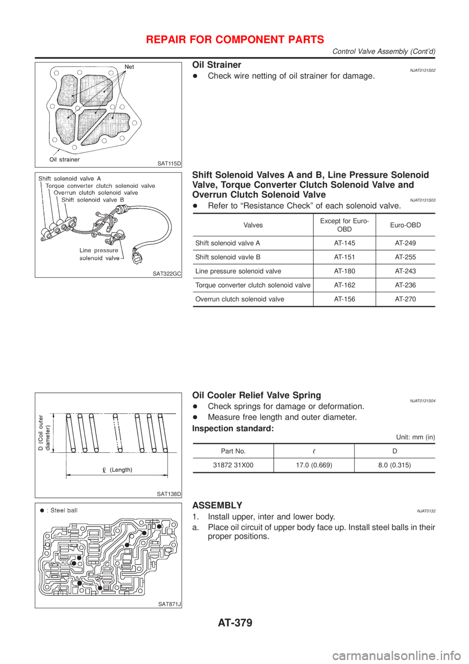
Oil StrainerNJAT0131S02+Check wire netting of oil strainer for damage.
SAT322GC
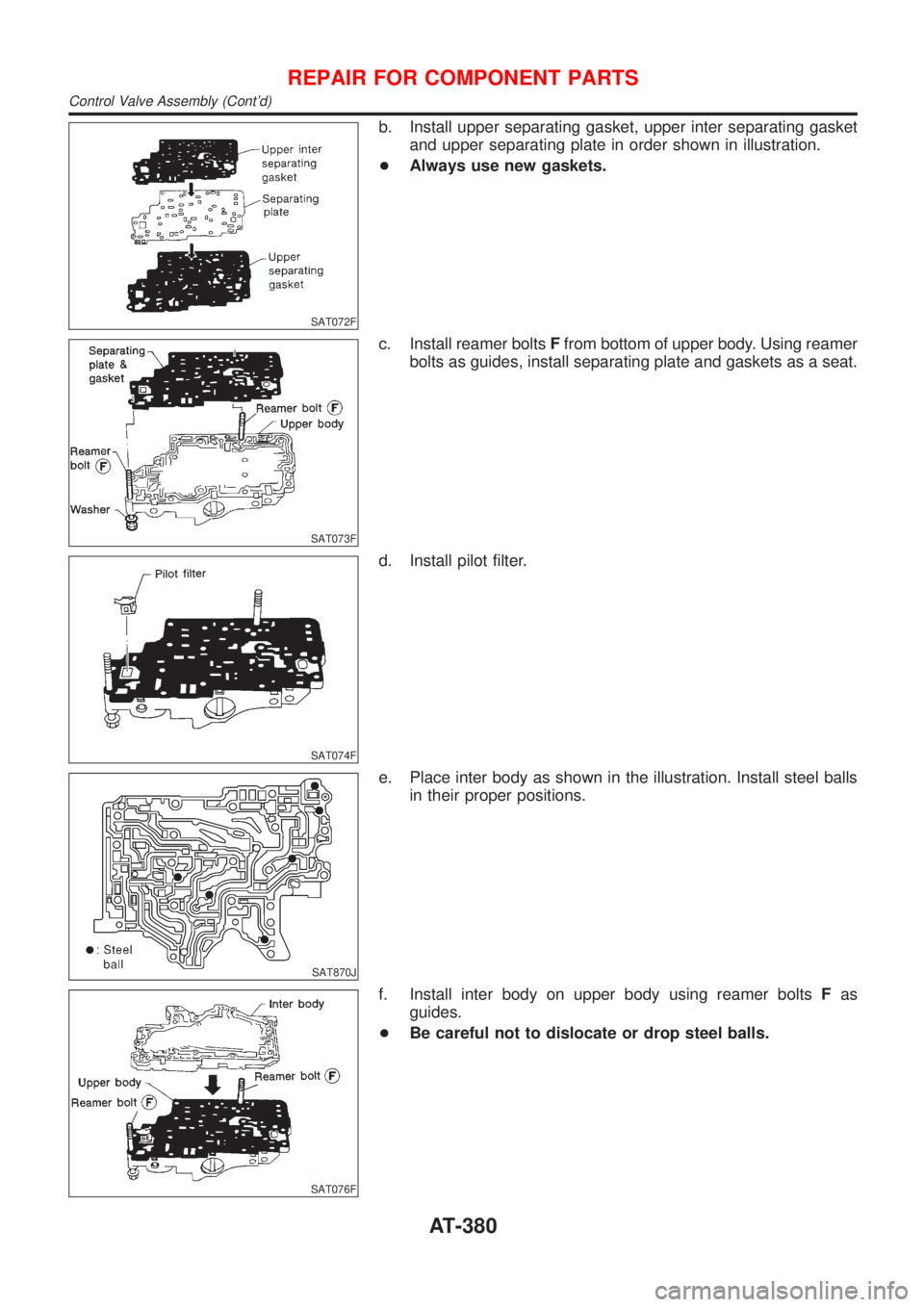
Shift Solenoid Valves A and B, Line Pressure Solenoid
Valve, Torque Converter Clutch Solenoid Valve and
Overrun Clutch Solenoid Valve
NJAT0131S03+Refer to ªResistance Checkº of each solenoid valve.
ValvesExcept for Euro-
OBDEuro-OBD
Shift solenoid valve A AT-145 AT-249
Shift solenoid vavle B AT-151 AT-255
Line pressure solenoid valve AT-180 AT-243
Torque converter clutch solenoid valve AT-162 AT-236
Overrun clutch solenoid valve AT-156 AT-270
SAT138D
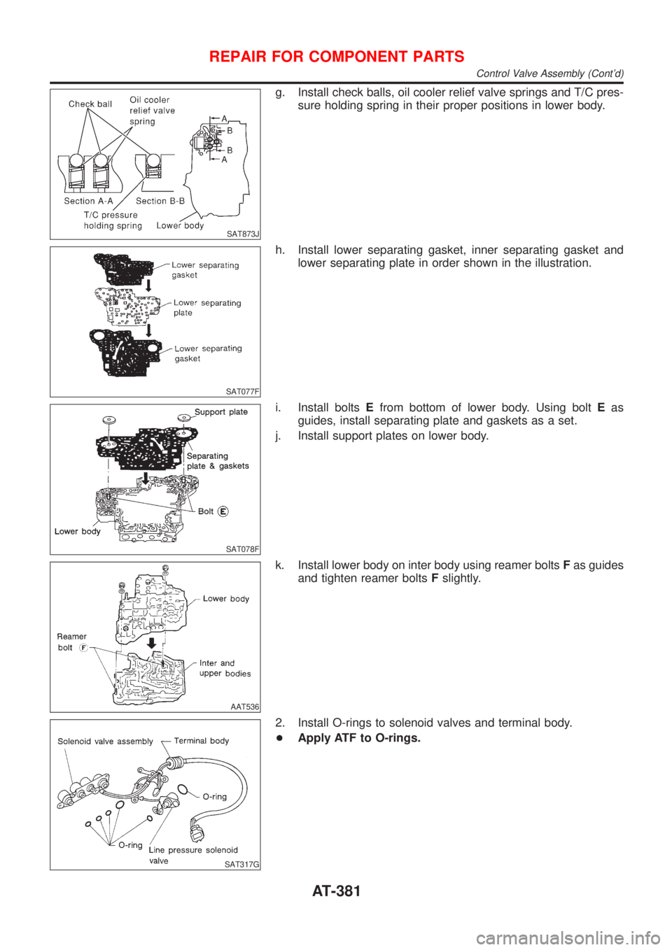
Oil Cooler Relief Valve SpringNJAT0131S04+Check springs for damage or deformation.
+Measure free length and outer diameter.
Inspection standard:
Unit: mm (in)
Part No.!D
31872 31X00 17.0 (0.669) 8.0 (0.315)
SAT871J
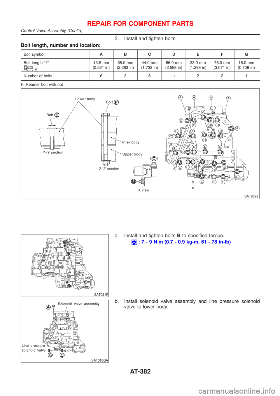
ASSEMBLYNJAT01321. Install upper, inter and lower body.
a. Place oil circuit of upper body face up. Install steel balls in their
proper positions.
REPAIR FOR COMPONENT PARTS
Control Valve Assembly (Cont'd)
AT-379
Page 1566 of 2493
SAT072F
b. Install upper separating gasket, upper inter separating gasket
and upper separating plate in order shown in illustration.
+Always use new gaskets.
SAT073F
c. Install reamer boltsFfrom bottom of upper body. Using reamer
bolts as guides, install separating plate and gaskets as a seat.
SAT074F
d. Install pilot filter.
SAT870J
e. Place inter body as shown in the illustration. Install steel balls
in their proper positions.
SAT076F
f. Install inter body on upper body using reamer boltsFas
guides.
+Be careful not to dislocate or drop steel balls.
REPAIR FOR COMPONENT PARTS
Control Valve Assembly (Cont'd)
AT-380
Page 1567 of 2493
SAT873J
g. Install check balls, oil cooler relief valve springs and T/C pres-
sure holding spring in their proper positions in lower body.
SAT077F
h. Install lower separating gasket, inner separating gasket and
lower separating plate in order shown in the illustration.
SAT078F
i. Install boltsEfrom bottom of lower body. Using boltEas
guides, install separating plate and gaskets as a set.
j. Install support plates on lower body.
AAT536
k. Install lower body on inter body using reamer boltsFas guides
and tighten reamer boltsFslightly.
SAT317G
2. Install O-rings to solenoid valves and terminal body.
+Apply ATF to O-rings.
REPAIR FOR COMPONENT PARTS
Control Valve Assembly (Cont'd)
AT-381
Page 1568 of 2493
3. Install and tighten bolts.
Bolt length, number and location:
Bolt symbolABCDE FG
Bolt length ª!º
13.5 mm
(0.531 in)58.0 mm
(2.283 in)44.0 mm
(1.732 in)66.0 mm
(2.598 in)33.0 mm
(1.299 in)78.0 mm
(3.071 in)18.0 mm
(0.709 in)
Number of bolts 6 3 6 11 2 2 1
F: Reamer bolt with nut
SAT869J
SAT081F
a. Install and tighten boltsBto specified torque.
:7-9N´m(0.7 - 0.9 kg-m, 61 - 78 in-lb)
SAT316GA
b. Install solenoid valve assembly and line pressure solenoid
valve to lower body.
REPAIR FOR COMPONENT PARTS
Control Valve Assembly (Cont'd)
AT-382
Page 1569 of 2493
SAT323G
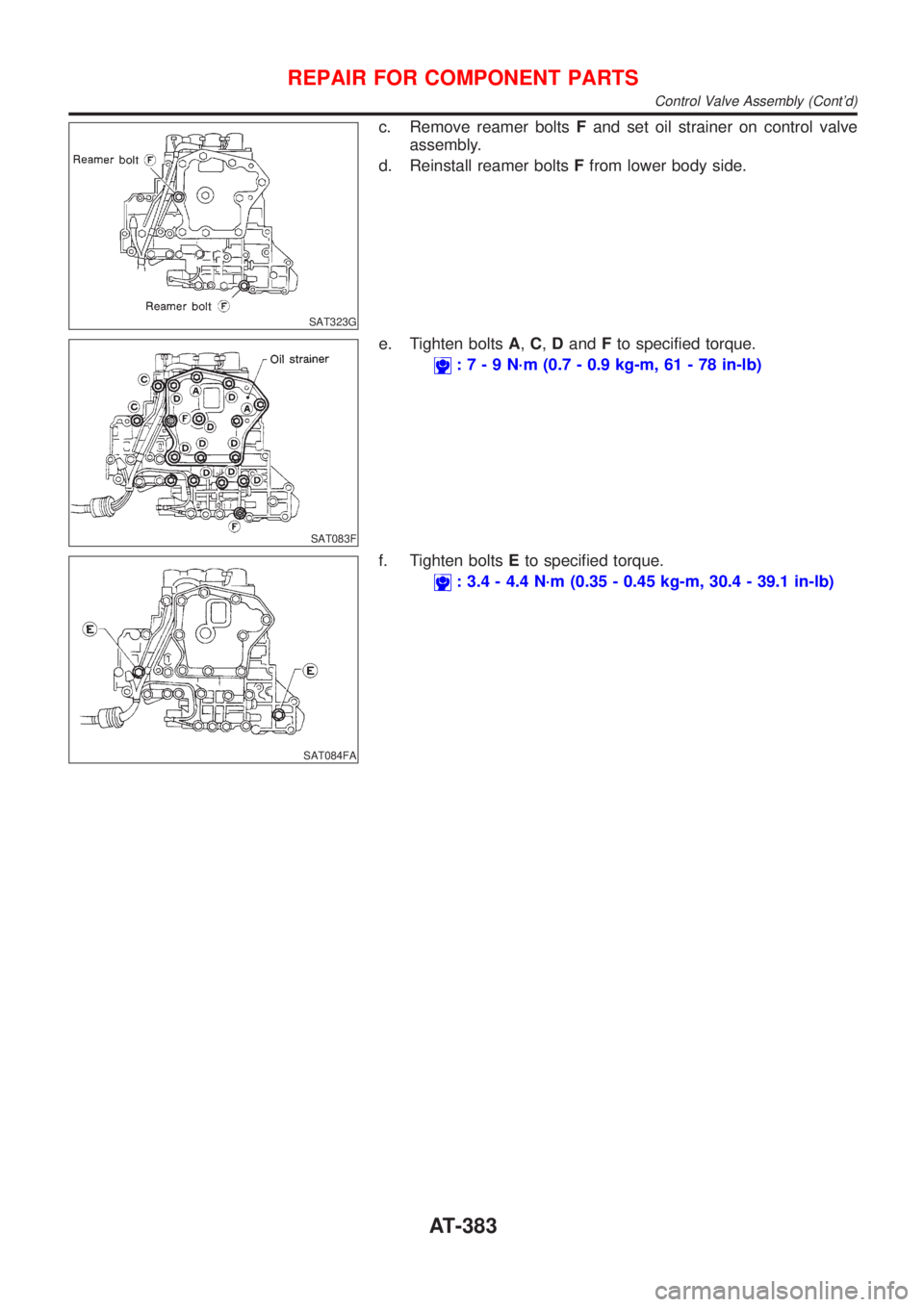
c. Remove reamer boltsFand set oil strainer on control valve
assembly.
d. Reinstall reamer boltsFfrom lower body side.
SAT083F
e. Tighten boltsA,C,DandFto specified torque.
:7-9N´m(0.7 - 0.9 kg-m, 61 - 78 in-lb)
SAT084FA
f. Tighten boltsEto specified torque.
: 3.4 - 4.4 N´m (0.35 - 0.45 kg-m, 30.4 - 39.1 in-lb)
REPAIR FOR COMPONENT PARTS
Control Valve Assembly (Cont'd)
AT-383
Page 1570 of 2493
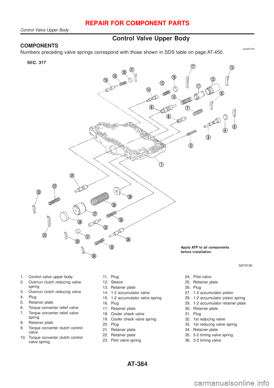
Control Valve Upper Body
COMPONENTS=NJAT0133Numbers preceding valve springs correspond with those shown in SDS table on page AT-450.
SAT012K
1. Control valve upper body
2. Overrun clutch reducing valve
spring
3. Overrun clutch reducing valve
4. Plug
5. Retainer plate
6. Torque converter relief valve
7. Torque converter relief valve
spring
8. Retainer plate
9. Torque converter clutch control
valve
10. Torque converter clutch control
valve spring11. Plug
12. Sleeve
13. Retainer plate
14. 1-2 accumulator valve
15. 1-2 accumulator valve spring
16. Plug
17. Retainer plate
18. Cooler check valve
19. Cooler check valve spring
20. Plug
21. Retainer plate
22. Retainer plate
23. Pilot valve spring24. Pilot valve
25. Retainer plate
26. Plug
27. 1-2 accumulator piston
28. 1-2 accumulator piston spring
29. 1-2 accumulator retainer plate
30. Retainer plate
31. Plug
32. 1st reducing valve
33. 1st reducing valve spring
34. Retainer plate
35. 3-2 timing valve spring
36. 3-2 timing valve
REPAIR FOR COMPONENT PARTS
Control Valve Upper Body
AT-384
Trending: trunk, P0110, spark plug, front suspension, trip computer, sat nav, headlamp
