NISSAN ALMERA N16 2001 Electronic Repair Manual
ALMERA N16 2001
NISSAN
NISSAN
https://www.carmanualsonline.info/img/5/57351/w960_57351-0.png
NISSAN ALMERA N16 2001 Electronic Repair Manual
Trending: ESP inoperative, width, air filter, fuses, Starter, p0325, warning lamp circuit
Page 1551 of 2493
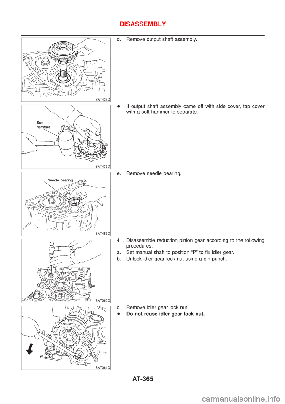
SAT439D
d. Remove output shaft assembly.
SAT435D
+If output shaft assembly came off with side cover, tap cover
with a soft hammer to separate.
SAT453D
e. Remove needle bearing.
SAT060D
41. Disassemble reduction pinion gear according to the following
procedures.
a. Set manual shaft to position ªPº to fix idler gear.
b. Unlock idler gear lock nut using a pin punch.
SAT061D
c. Remove idler gear lock nut.
+Do not reuse idler gear lock nut.
DISASSEMBLY
AT-365
Page 1552 of 2493
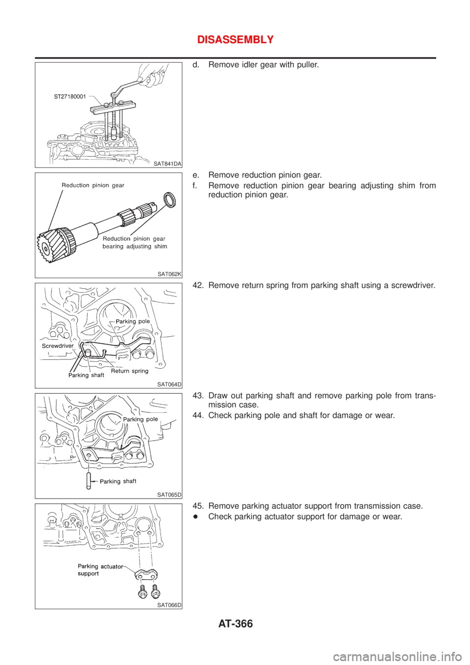
SAT841DA
d. Remove idler gear with puller.
SAT062K
e. Remove reduction pinion gear.
f. Remove reduction pinion gear bearing adjusting shim from
reduction pinion gear.
SAT064D
42. Remove return spring from parking shaft using a screwdriver.
SAT065D
43. Draw out parking shaft and remove parking pole from trans-
mission case.
44. Check parking pole and shaft for damage or wear.
SAT066D
45. Remove parking actuator support from transmission case.
+Check parking actuator support for damage or wear.
DISASSEMBLY
AT-366
Page 1553 of 2493
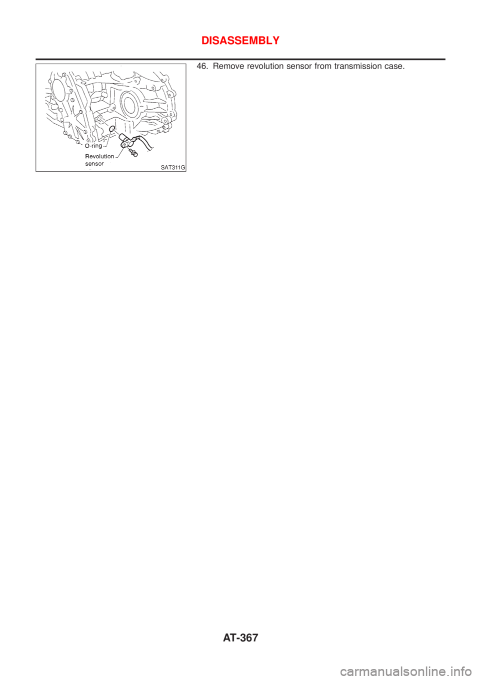
SAT311G
46. Remove revolution sensor from transmission case.
DISASSEMBLY
AT-367
Page 1554 of 2493
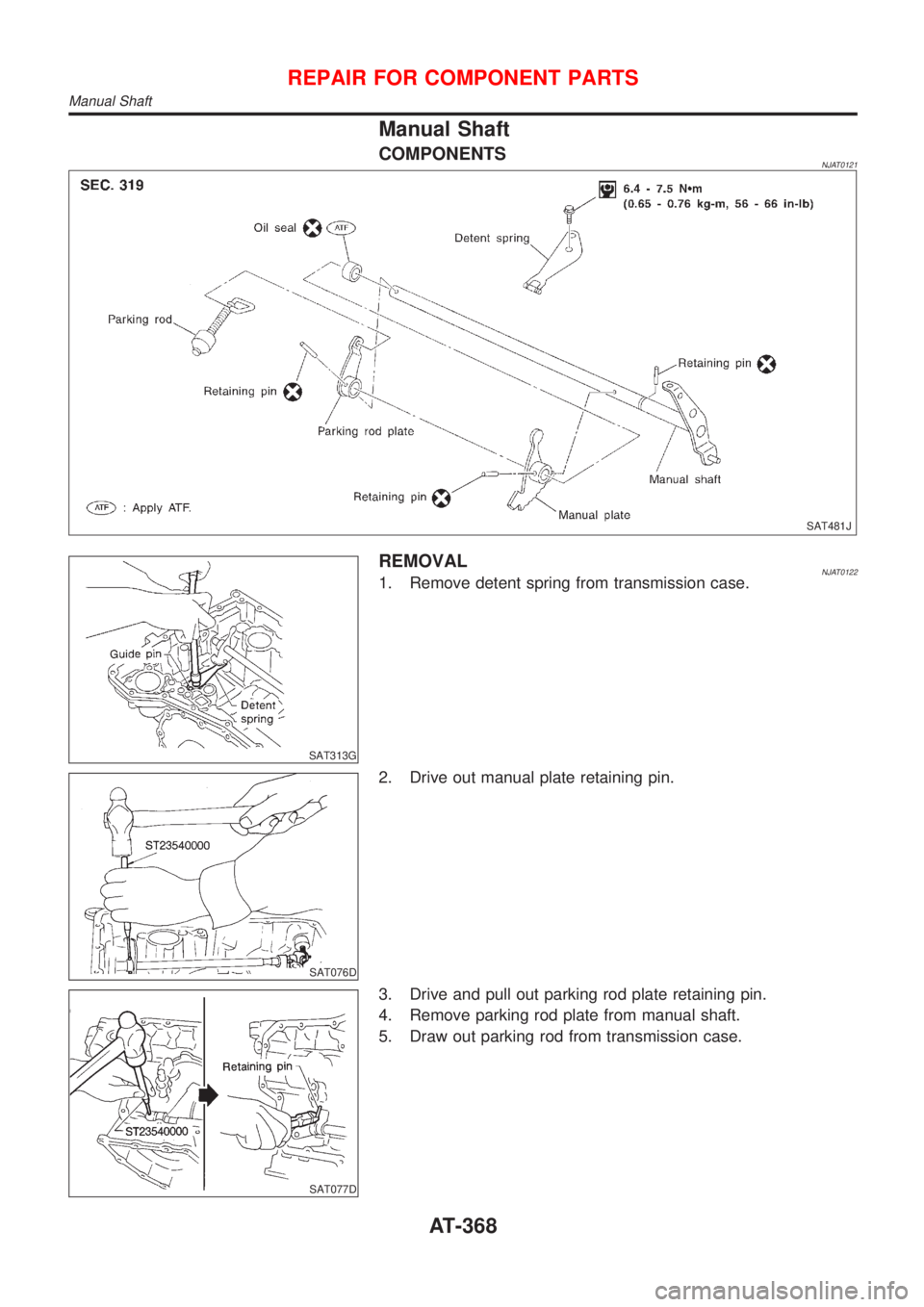
Manual Shaft
COMPONENTSNJAT0121
SAT481J
SAT313G
REMOVALNJAT01221. Remove detent spring from transmission case.
SAT076D
2. Drive out manual plate retaining pin.
SAT077D
3. Drive and pull out parking rod plate retaining pin.
4. Remove parking rod plate from manual shaft.
5. Draw out parking rod from transmission case.
REPAIR FOR COMPONENT PARTS
Manual Shaft
AT-368
Page 1555 of 2493
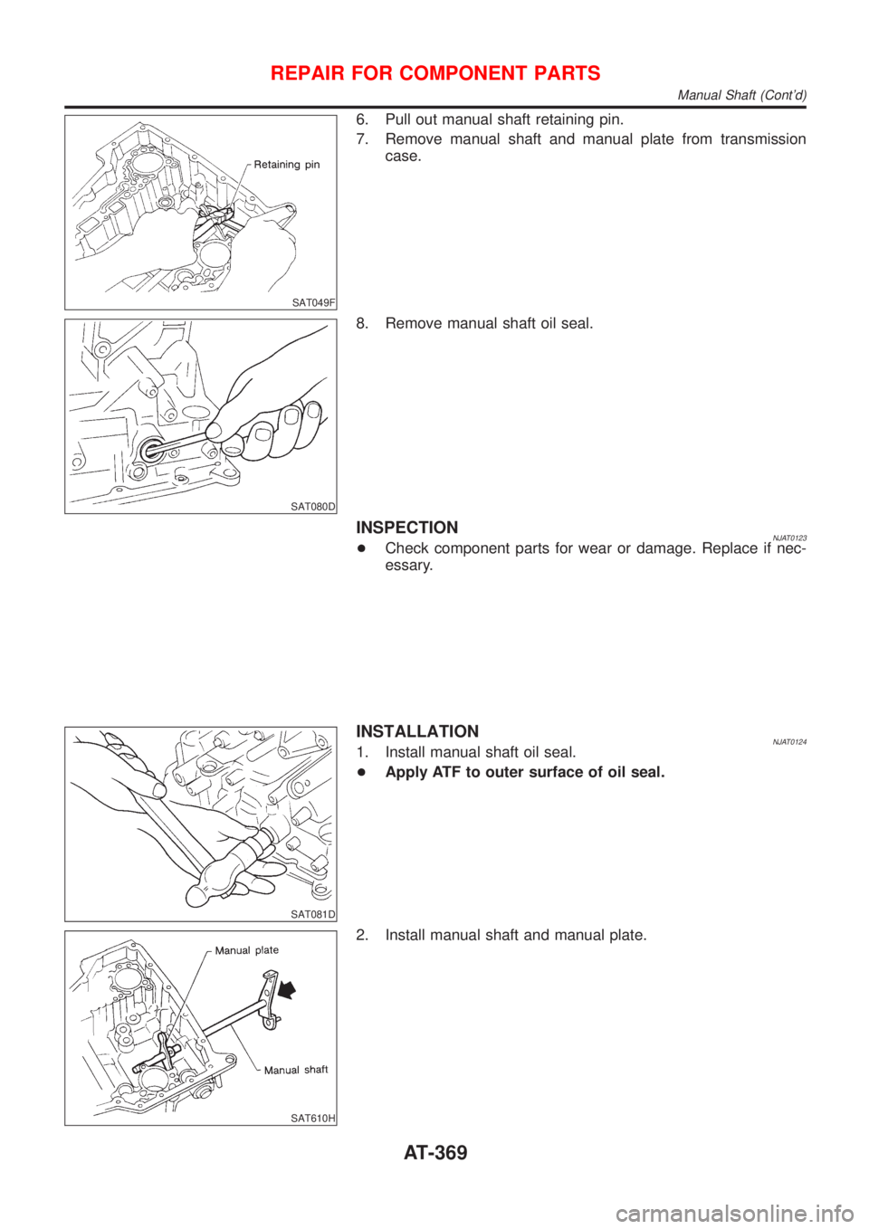
SAT049F
6. Pull out manual shaft retaining pin.
7. Remove manual shaft and manual plate from transmission
case.
SAT080D
8. Remove manual shaft oil seal.
INSPECTIONNJAT0123+Check component parts for wear or damage. Replace if nec-
essary.
SAT081D
INSTALLATIONNJAT01241. Install manual shaft oil seal.
+Apply ATF to outer surface of oil seal.
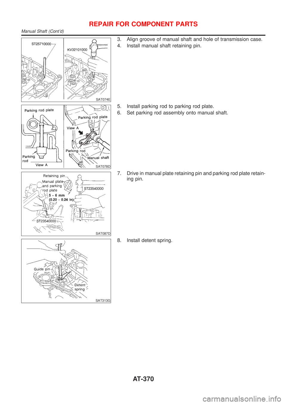
SAT610H
2. Install manual shaft and manual plate.
REPAIR FOR COMPONENT PARTS
Manual Shaft (Cont'd)
AT-369
Page 1556 of 2493
SAT074E
3. Align groove of manual shaft and hole of transmission case.
4. Install manual shaft retaining pin.
SAT078D
5. Install parking rod to parking rod plate.
6. Set parking rod assembly onto manual shaft.
SAT087D
7. Drive in manual plate retaining pin and parking rod plate retain-
ing pin.
SAT313G
8. Install detent spring.
REPAIR FOR COMPONENT PARTS
Manual Shaft (Cont'd)
AT-370
Page 1557 of 2493
Oil Pump
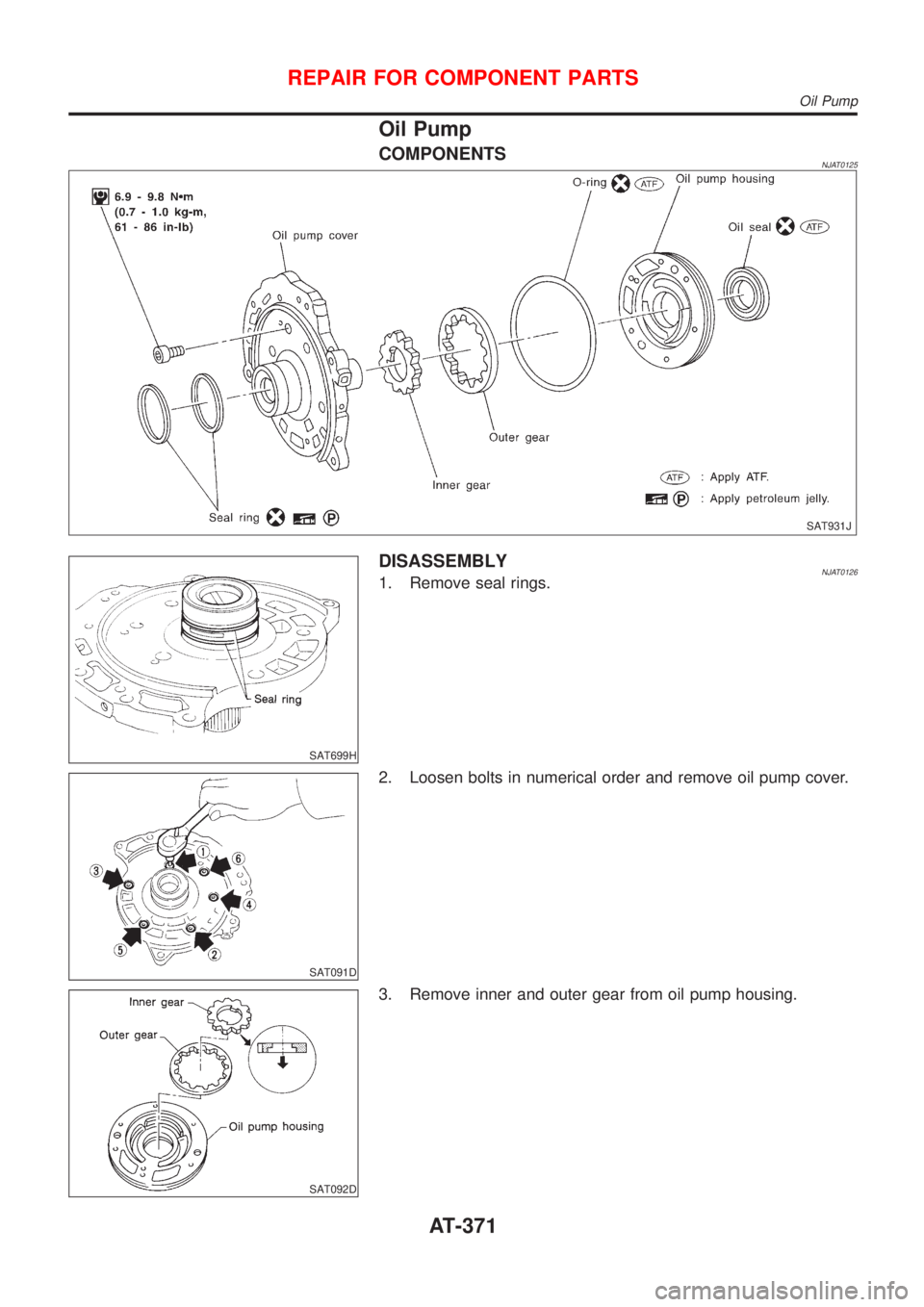
COMPONENTSNJAT0125
SAT931J
SAT699H
DISASSEMBLYNJAT01261. Remove seal rings.
SAT091D
2. Loosen bolts in numerical order and remove oil pump cover.
SAT092D
3. Remove inner and outer gear from oil pump housing.
REPAIR FOR COMPONENT PARTS
Oil Pump
AT-371
Page 1558 of 2493
SAT093D
4. Remove O-ring from oil pump housing.
SAT094D
5. Remove oil pump housing oil seal.
INSPECTIONNJAT0127Oil Pump Housing, Oil Pump Cover, Inner Gear and
Outer Gear
NJAT0127S01+Check for wear or damage.
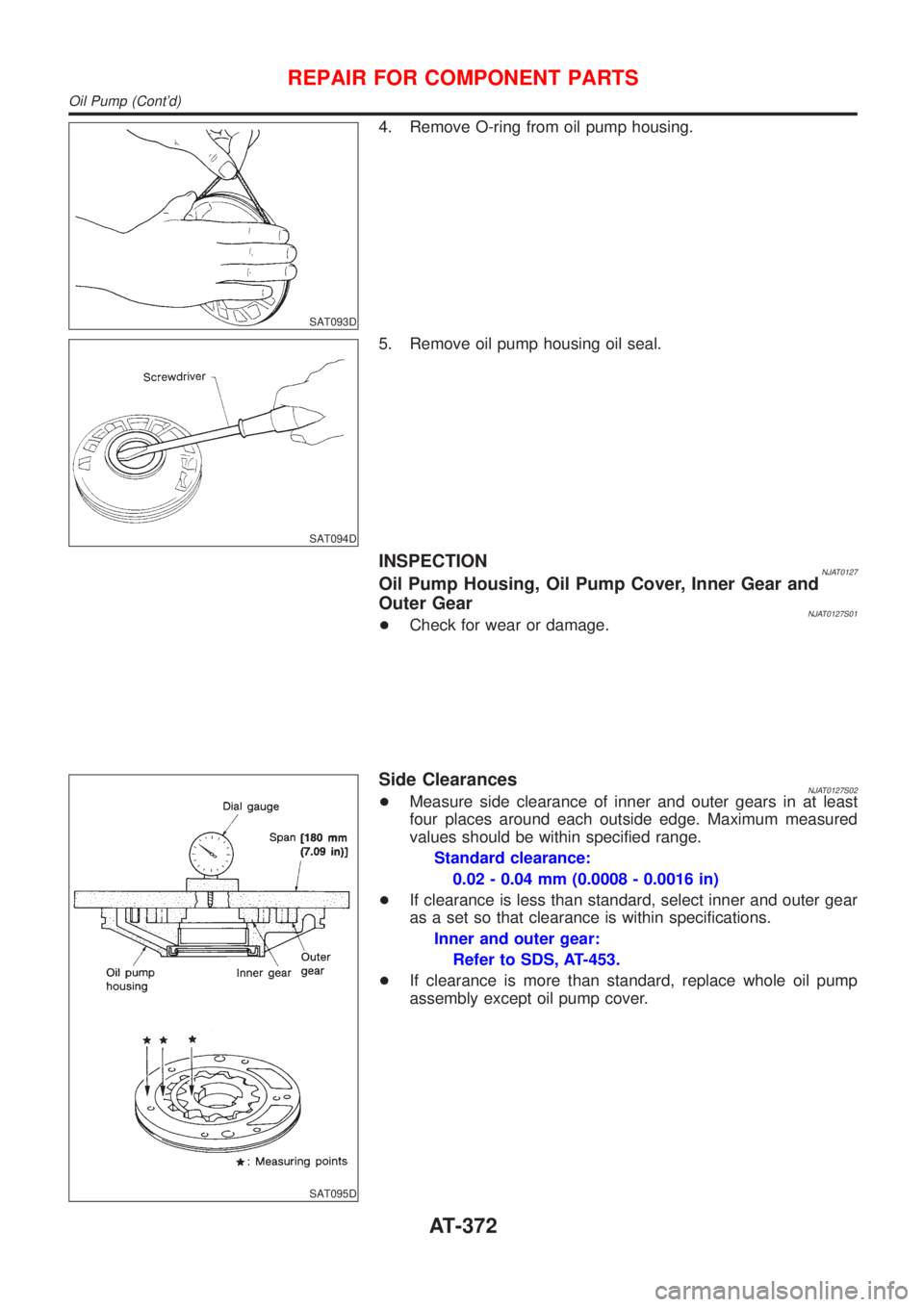
SAT095D
Side ClearancesNJAT0127S02+Measure side clearance of inner and outer gears in at least
four places around each outside edge. Maximum measured
values should be within specified range.
Standard clearance:
0.02 - 0.04 mm (0.0008 - 0.0016 in)
+If clearance is less than standard, select inner and outer gear
as a set so that clearance is within specifications.
Inner and outer gear:
Refer to SDS, AT-453.
+If clearance is more than standard, replace whole oil pump
assembly except oil pump cover.
REPAIR FOR COMPONENT PARTS
Oil Pump (Cont'd)
AT-372
Page 1559 of 2493
SAT096D
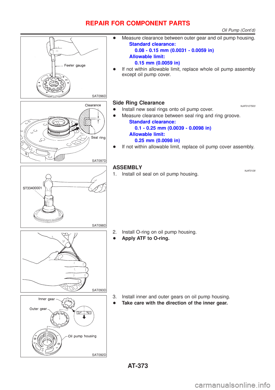
+Measure clearance between outer gear and oil pump housing.
Standard clearance:
0.08 - 0.15 mm (0.0031 - 0.0059 in)
Allowable limit:
0.15 mm (0.0059 in)
+If not within allowable limit, replace whole oil pump assembly
except oil pump cover.
SAT097D
Side Ring ClearanceNJAT0127S03+Install new seal rings onto oil pump cover.
+Measure clearance between seal ring and ring groove.
Standard clearance:
0.1 - 0.25 mm (0.0039 - 0.0098 in)
Allowable limit:
0.25 mm (0.0098 in)
+If not within allowable limit, replace oil pump cover assembly.
SAT098D
ASSEMBLYNJAT01281. Install oil seal on oil pump housing.
SAT093D
2. Install O-ring on oil pump housing.
+Apply ATF to O-ring.
SAT092D
3. Install inner and outer gears on oil pump housing.
+Take care with the direction of the inner gear.
REPAIR FOR COMPONENT PARTS
Oil Pump (Cont'd)
AT-373
Page 1560 of 2493
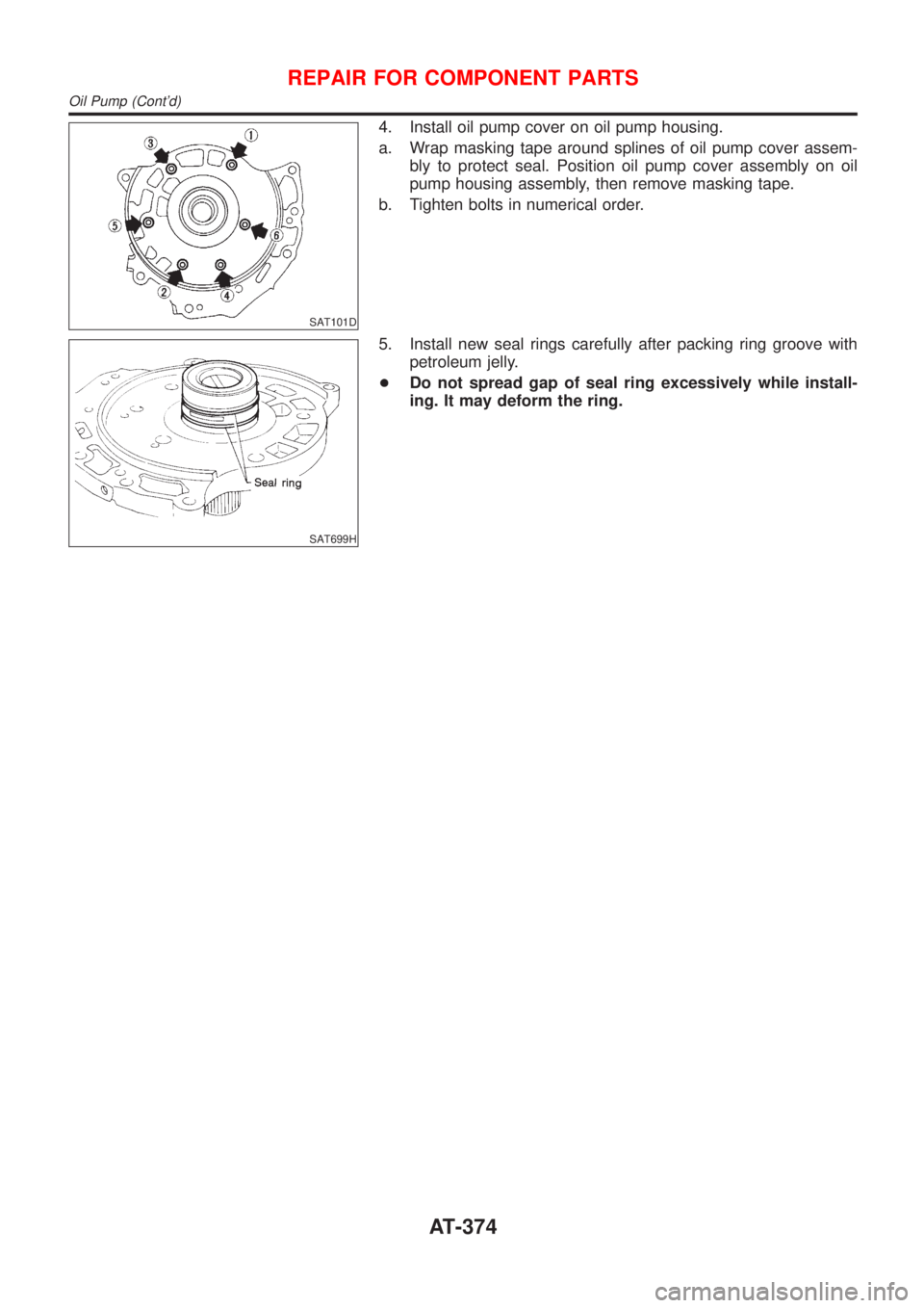
SAT101D
4. Install oil pump cover on oil pump housing.
a. Wrap masking tape around splines of oil pump cover assem-
bly to protect seal. Position oil pump cover assembly on oil
pump housing assembly, then remove masking tape.
b. Tighten bolts in numerical order.
SAT699H
5. Install new seal rings carefully after packing ring groove with
petroleum jelly.
+Do not spread gap of seal ring excessively while install-
ing. It may deform the ring.
REPAIR FOR COMPONENT PARTS
Oil Pump (Cont'd)
AT-374
Trending: conditioner, automatic transmission, compression ratio, radiator cap, language, service, trunk
