NISSAN ALMERA N16 2001 Electronic Repair Manual
Manufacturer: NISSAN, Model Year: 2001, Model line: ALMERA N16, Model: NISSAN ALMERA N16 2001Pages: 2493, PDF Size: 66.97 MB
Page 291 of 2493
JLC295B
Changing Engine CoolantNJLC0079WARNING:
To avoid the danger of being scalded, never change the cool-
ant when the engine is hot.
Ð DRAINING ENGINE COOLANT ÐNJLC0079S011. Set air conditioning system as follows to prevent coolant from
remaining in the system.
a. Turn ignition switch ON and set temperature controller to maxi-
mum hot position.
b. Wait 10 seconds before turning ignition switch OFF.
SMA033D
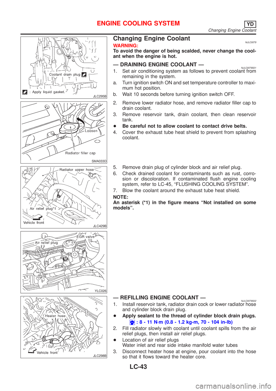
2. Remove lower radiator hose, and remove radiator filler cap to
drain coolant.
3. Remove reservoir tank, drain coolant, then clean reservoir
tank.
+Be careful not to allow coolant to contact drive belts.
4. Cover the exhaust tube heat shield to prevent from splashing
coolant.
JLC429B
YLC026
5. Remove drain plug of cylinder block and air relief plug.
6. Check drained coolant for contaminants such as rust, corro-
sion or discoloration. If contaminated flush engine cooling
system, refer to LC-45, ªFLUSHING COOLING SYSTEMº.
7. Blow the coolant around the exhaust tube heat shield.
NOTE:
An asterisk (*1) in the figure means ªNot installed on some
modelsº.
JLC298B
Ð REFILLING ENGINE COOLANT ÐNJLC0079S021. Install reservoir tank, radiator drain cock or lower radiator hose
and cylinder block drain plug.
+Apply sealant to the thread of cylinder block drain plugs.
:8-11N´m(0.8 - 1.2 kg-m, 70 - 104 in-lb)
2. Fill radiator slowly with coolant until coolant spills from the air
relief plugs, then install air relief plugs.
+Location of air relief plugs
Water inlet and rear side intake manifold water tubes
3. Disconnect heater hose at engine, pour coolant into the hose
so that it flows toward the heater core.
ENGINE COOLING SYSTEMYD
Changing Engine Coolant
LC-43
Page 292 of 2493
+While filling, if coolant from engine side spills out, be sure to
reconnect the heater hose.
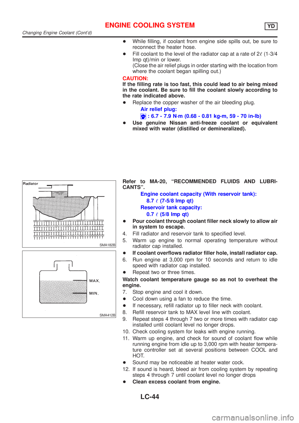
+Fill coolant to the level of the radiator cap at a rate of 2!(1-3/4
Imp qt)/min or lower.
(Close the air relief plugs in order starting with the location from
where the coolant began spilling out.)
CAUTION:
If the filling rate is too fast, this could lead to air being mixed
in the coolant. Be sure to fill the coolant slowly according to
the rate indicated above.
+Replace the copper washer of the air bleeding plug.
Air relief plug:
: 6.7 - 7.9 N´m (0.68 - 0.81 kg-m, 59 - 70 in-lb)
+Use genuine Nissan anti-freeze coolant or equivalent
mixed with water (distilled or demineralized).
SMA182B
SMA412B
Refer to MA-20, ªRECOMMENDED FLUIDS AND LUBRI-
CANTSº.
Engine coolant capacity (With reservoir tank):
8.7!(7-5/8 Imp qt)
Reservoir tank capacity:
0.7!(5/8 Imp qt)
+Pour coolant through coolant filler neck slowly to allow air
in system to escape.
4. Fill radiator and reservoir tank to specified level.
5. Warm up engine to normal operating temperature without
radiator cap installed.
+If coolant overflows radiator filler hole, install radiator cap.
6. Run engine at 3,000 rpm for 10 seconds and return to idle
speed with radiator cap installed.
+Repeat two or three times.
Watch coolant temperature gauge so as not to overheat the
engine.
7. Stop engine and cool it down.
+Cool down using a fan to reduce the time.
+If necessary, refill radiator up to filler neck with coolant.
8. Refill reservoir tank to MAX level line with coolant.
9. Repeat steps 4 through 7 two or more times with radiator cap
installed until coolant level no longer drops.
10. Check cooling system for leaks with engine running.
11. Warm up engine, and check for sound of coolant flow while
running engine from idle up to 3,000 rpm with heater tempera-
ture controller set at several positions between COOL and
HOT.
+Sound may be noticeable at heater water cock.
12. If sound is heard, bleed air from cooling system by repeating
steps 4 through 7 until coolant level no longer drops
+Clean excess coolant from engine.
ENGINE COOLING SYSTEMYD
Changing Engine Coolant (Cont'd)
LC-44
Page 293 of 2493
Ð FLUSHING COOLING SYSTEM ÐNJLC0079S031. Open air relief plug.
2. Fill radiator with water until water spills from the air relief hole,
then close air relief plug. Fill radiator and reservoir tank with
water and reinstall radiator cap.
3. Run engine and warm it up to normal operating temperature.
4. Rev engine two or three times under no-load.
5. Stop engine and wait until it cools down.
6. Drain water.
7. Repeat steps 1 through 6 until clear water begins to drain from
radiator.
ENGINE COOLING SYSTEMYD
Changing Engine Coolant (Cont'd)
LC-45
Page 294 of 2493
Radiator (Aluminum type)=NJLC0082Refer to LC-20, ªRadiator (Aluminum type)º.
Overheating Cause AnalysisNJLC0070
Symptom Check items
Cooling sys-
tem parts
malfunctionPoor heat transferWater pump malfunction Worn or loose drive belt
Ð Thermostat stuck closed Ð
Damaged finsDust contamination or
paper clogging
Mechanical damage
Clogged radiator cooling
tubeExcess foreign material
(rust, dirt, sand, etc.)
Reduced air flowCooling fan does not oper-
ate
ÐÐ High resistance to fan rota-
tion
Damaged fan blades
Damaged radiator shroud Ð Ð Ð
Improper coolant mixture
ratioÐÐÐ
Poor coolant quality Ð Ð Ð
Insufficient coolantCoolant leaksCooling hoseLoose clamp
Cracked hose
Water pump Poor sealing
Radiator capLoose
Poor sealing
RadiatorO-ring for damage, dete-
rioration or improper fit-
ting
Cracked radiator tank
Cracked radiator core
Reservoir tank Cracked reservoir tank
Overflowing reservoir tankExhaust gas leaks into
cooling systemCylinder head deteriora-
tion
Cylinder head gasket
deterioration
ENGINE COOLING SYSTEMYD
Radiator (Aluminum type)
LC-46
Page 295 of 2493
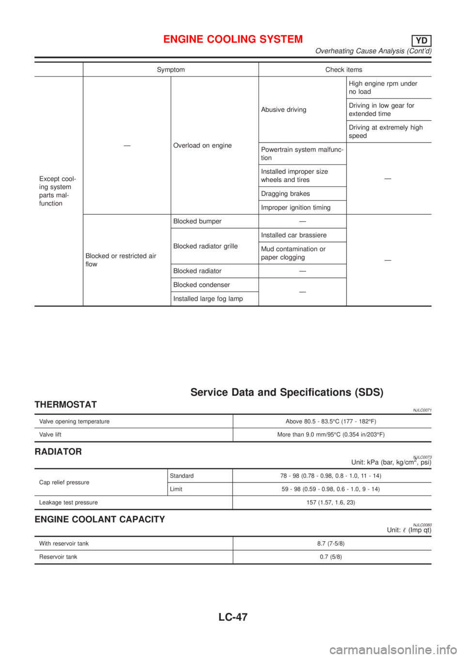
Symptom Check items
Except cool-
ing system
parts mal-
functionÐ Overload on engineAbusive drivingHigh engine rpm under
no load
Driving in low gear for
extended time
Driving at extremely high
speed
Powertrain system malfunc-
tion
Ð Installed improper size
wheels and tires
Dragging brakes
Improper ignition timing
Blocked or restricted air
flowBlocked bumper Ð
Ð Blocked radiator grilleInstalled car brassiere
Mud contamination or
paper clogging
Blocked radiator Ð
Blocked condenser
Ð
Installed large fog lamp
Service Data and Specifications (SDS)
THERMOSTATNJLC0071
Valve opening temperature Above 80.5 - 83.5ÉC (177 - 182ÉF)
Valve liftMore than 9.0 mm/95ÉC (0.354 in/203ÉF)
RADIATORNJLC0073Unit: kPa (bar, kg/cm2, psi)
Cap relief pressureStandard 78 - 98 (0.78 - 0.98, 0.8 - 1.0, 11 - 14)
Limit 59 - 98 (0.59 - 0.98, 0.6 - 1.0,9-14)
Leakage test pressure157 (1.57, 1.6, 23)
ENGINE COOLANT CAPACITYNJLC0080Unit:!(Imp qt)
With reservoir tank8.7 (7-5/8)
Reservoir tank0.7 (5/8)
ENGINE COOLING SYSTEMYD
Overheating Cause Analysis (Cont'd)
LC-47
Page 296 of 2493
ENGINE COOLING SYSTEM
Service Data and Specifications (SDS) (Cont'd)
LC-48
Page 297 of 2493
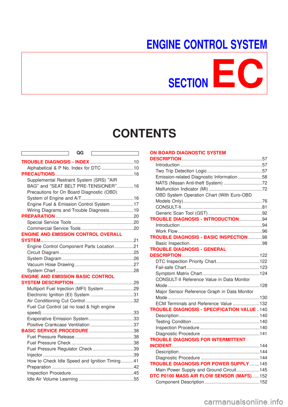
ENGINE CONTROL SYSTEM
SECTION
EC
CONTENTS
QG
TROUBLE DIAGNOSIS - INDEX..................................10
Alphabetical & P No. Index for DTC .........................10
PRECAUTIONS.............................................................16
Supplemental Restraint System (SRS)²AIR
BAG²and²SEAT BELT PRE-TENSIONER².............16
Precautions for On Board Diagnostic (OBD)
System of Engine and A/T.........................................16
Engine Fuel & Emission Control System ..................17
Wiring Diagrams and Trouble Diagnosis ...................19
PREPARATION.............................................................20
Special Service Tools ................................................20
Commercial Service Tools .........................................20
ENGINE AND EMISSION CONTROL OVERALL
SYSTEM.........................................................................21
Engine Control Component Parts Location ...............21
Circuit Diagram ..........................................................25
System Diagram ........................................................26
Vacuum Hose Drawing ..............................................27
System Chart .............................................................28
ENGINE AND EMISSION BASIC CONTROL
SYSTEM DESCRIPTION...............................................29
Multiport Fuel Injection (MFI) System .......................29
Electronic Ignition (EI) System ..................................31
Air Conditioning Cut Control ......................................32
Fuel Cut Control (at no load & high engine
speed) ........................................................................33
Evaporative Emission System ...................................33
Positive Crankcase Ventilation ..................................37
BASIC SERVICE PROCEDURE...................................38
Fuel Pressure Release ..............................................38
Fuel Pressure Check .................................................38
Fuel Pressure Regulator Check ................................39
Injector .......................................................................39
How to Check Idle Speed and Ignition Timing ..........41
Preparation ................................................................42
Inspection Procedure .................................................45
Idle Air Volume Learning ...........................................55ON BOARD DIAGNOSTIC SYSTEM
DESCRIPTION...............................................................57
Introduction ................................................................57
Two Trip Detection Logic ...........................................57
Emission-related Diagnostic Information ...................58
NATS (Nissan Anti-theft System) ..............................72
Malfunction Indicator (MI) ..........................................72
OBD System Operation Chart (With Euro-OBD
Models Only)..............................................................76
CONSULT-II ...............................................................81
Generic Scan Tool (GST) ..........................................92
TROUBLE DIAGNOSIS - INTRODUCTION..................94
Introduction ................................................................94
Work Flow ..................................................................96
TROUBLE DIAGNOSIS - BASIC INSPECTION...........98
Basic Inspection.........................................................98
TROUBLE DIAGNOSIS - GENERAL
DESCRIPTION.............................................................122
DTC Inspection Priority Chart..................................122
Fail-safe Chart .........................................................123
Symptom Matrix Chart .............................................124
CONSULT-II Reference Value in Data Monitor
Mode ........................................................................128
Major Sensor Reference Graph in Data Monitor
Mode ........................................................................130
ECM Terminals and Reference Value .....................132
TROUBLE DIAGNOSIS - SPECIFICATION VALUE..140
Description ...............................................................140
Testing Condition .....................................................140
Inspection Procedure ...............................................140
Diagnostic Procedure ..............................................141
TROUBLE DIAGNOSIS FOR INTERMITTENT
INCIDENT.....................................................................144
Description ...............................................................144
Diagnostic Procedure ..............................................144
TROUBLE DIAGNOSIS FOR POWER SUPPLY........145
Main Power Supply and Ground Circuit ..................145
DTC P0100 MASS AIR FLOW SENSOR (MAFS)......152
Component Description ...........................................152
Page 298 of 2493
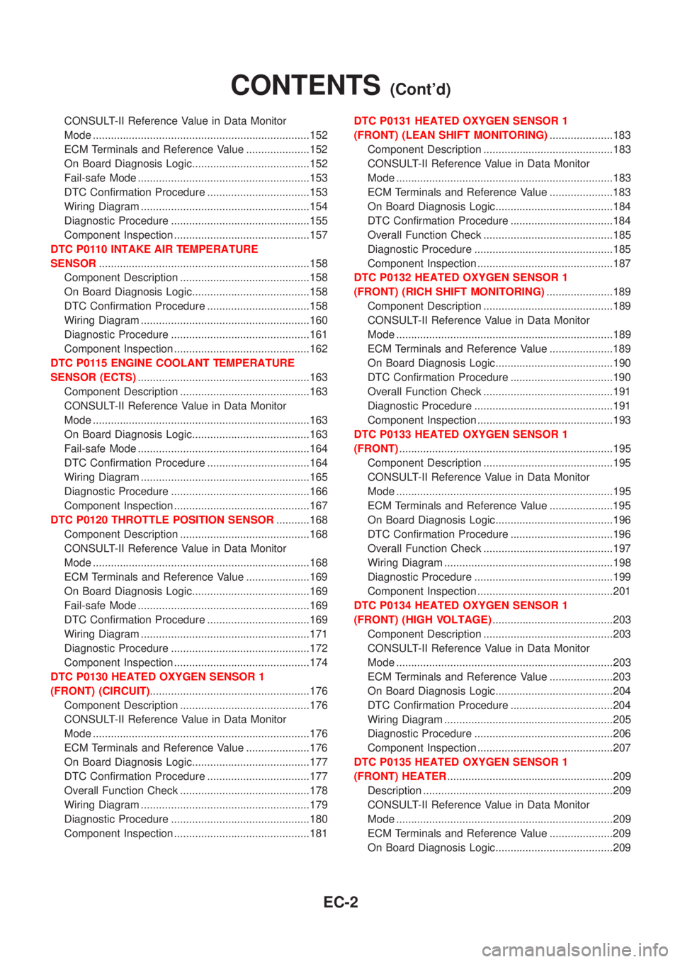
CONSULT-II Reference Value in Data Monitor
Mode ........................................................................152
ECM Terminals and Reference Value .....................152
On Board Diagnosis Logic.......................................152
Fail-safe Mode .........................................................153
DTC Confirmation Procedure ..................................153
Wiring Diagram ........................................................154
Diagnostic Procedure ..............................................155
Component Inspection .............................................157
DTC P0110 INTAKE AIR TEMPERATURE
SENSOR......................................................................158
Component Description ...........................................158
On Board Diagnosis Logic.......................................158
DTC Confirmation Procedure ..................................158
Wiring Diagram ........................................................160
Diagnostic Procedure ..............................................161
Component Inspection .............................................162
DTC P0115 ENGINE COOLANT TEMPERATURE
SENSOR (ECTS).........................................................163
Component Description ...........................................163
CONSULT-II Reference Value in Data Monitor
Mode ........................................................................163
On Board Diagnosis Logic.......................................163
Fail-safe Mode .........................................................164
DTC Confirmation Procedure ..................................164
Wiring Diagram ........................................................165
Diagnostic Procedure ..............................................166
Component Inspection .............................................167
DTC P0120 THROTTLE POSITION SENSOR...........168
Component Description ...........................................168
CONSULT-II Reference Value in Data Monitor
Mode ........................................................................168
ECM Terminals and Reference Value .....................169
On Board Diagnosis Logic.......................................169
Fail-safe Mode .........................................................169
DTC Confirmation Procedure ..................................169
Wiring Diagram ........................................................171
Diagnostic Procedure ..............................................172
Component Inspection .............................................174
DTC P0130 HEATED OXYGEN SENSOR 1
(FRONT) (CIRCUIT).....................................................176
Component Description ...........................................176
CONSULT-II Reference Value in Data Monitor
Mode ........................................................................176
ECM Terminals and Reference Value .....................176
On Board Diagnosis Logic.......................................177
DTC Confirmation Procedure ..................................177
Overall Function Check ...........................................178
Wiring Diagram ........................................................179
Diagnostic Procedure ..............................................180
Component Inspection .............................................181DTC P0131 HEATED OXYGEN SENSOR 1
(FRONT) (LEAN SHIFT MONITORING).....................183
Component Description ...........................................183
CONSULT-II Reference Value in Data Monitor
Mode ........................................................................183
ECM Terminals and Reference Value .....................183
On Board Diagnosis Logic.......................................184
DTC Confirmation Procedure ..................................184
Overall Function Check ...........................................185
Diagnostic Procedure ..............................................185
Component Inspection .............................................187
DTC P0132 HEATED OXYGEN SENSOR 1
(FRONT) (RICH SHIFT MONITORING)......................189
Component Description ...........................................189
CONSULT-II Reference Value in Data Monitor
Mode ........................................................................189
ECM Terminals and Reference Value .....................189
On Board Diagnosis Logic.......................................190
DTC Confirmation Procedure ..................................190
Overall Function Check ...........................................191
Diagnostic Procedure ..............................................191
Component Inspection .............................................193
DTC P0133 HEATED OXYGEN SENSOR 1
(FRONT).......................................................................195
Component Description ...........................................195
CONSULT-II Reference Value in Data Monitor
Mode ........................................................................195
ECM Terminals and Reference Value .....................195
On Board Diagnosis Logic.......................................196
DTC Confirmation Procedure ..................................196
Overall Function Check ...........................................197
Wiring Diagram ........................................................198
Diagnostic Procedure ..............................................199
Component Inspection .............................................201
DTC P0134 HEATED OXYGEN SENSOR 1
(FRONT) (HIGH VOLTAGE)........................................203
Component Description ...........................................203
CONSULT-II Reference Value in Data Monitor
Mode ........................................................................203
ECM Terminals and Reference Value .....................203
On Board Diagnosis Logic.......................................204
DTC Confirmation Procedure ..................................204
Wiring Diagram ........................................................205
Diagnostic Procedure ..............................................206
Component Inspection .............................................207
DTC P0135 HEATED OXYGEN SENSOR 1
(FRONT) HEATER.......................................................209
Description ...............................................................209
CONSULT-II Reference Value in Data Monitor
Mode ........................................................................209
ECM Terminals and Reference Value .....................209
On Board Diagnosis Logic.......................................209
CONTENTS(Cont'd)
EC-2
Page 299 of 2493
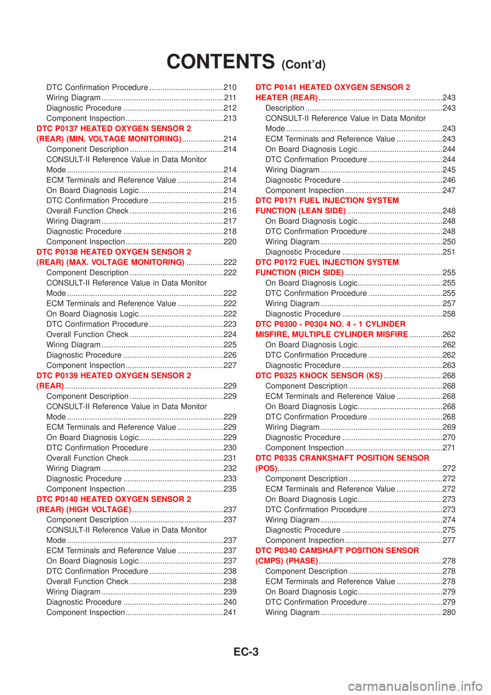
DTC Confirmation Procedure ..................................210
Wiring Diagram ........................................................ 211
Diagnostic Procedure ..............................................212
Component Inspection .............................................213
DTC P0137 HEATED OXYGEN SENSOR 2
(REAR) (MIN. VOLTAGE MONITORING)...................214
Component Description ...........................................214
CONSULT-II Reference Value in Data Monitor
Mode ........................................................................214
ECM Terminals and Reference Value .....................214
On Board Diagnosis Logic.......................................214
DTC Confirmation Procedure ..................................215
Overall Function Check ...........................................216
Wiring Diagram ........................................................217
Diagnostic Procedure ..............................................218
Component Inspection .............................................220
DTC P0138 HEATED OXYGEN SENSOR 2
(REAR) (MAX. VOLTAGE MONITORING).................222
Component Description ...........................................222
CONSULT-II Reference Value in Data Monitor
Mode ........................................................................222
ECM Terminals and Reference Value .....................222
On Board Diagnosis Logic.......................................222
DTC Confirmation Procedure ..................................223
Overall Function Check ...........................................224
Wiring Diagram ........................................................225
Diagnostic Procedure ..............................................226
Component Inspection .............................................227
DTC P0139 HEATED OXYGEN SENSOR 2
(REAR).........................................................................229
Component Description ...........................................229
CONSULT-II Reference Value in Data Monitor
Mode ........................................................................229
ECM Terminals and Reference Value .....................229
On Board Diagnosis Logic.......................................229
DTC Confirmation Procedure ..................................230
Overall Function Check ...........................................231
Wiring Diagram ........................................................232
Diagnostic Procedure ..............................................233
Component Inspection .............................................235
DTC P0140 HEATED OXYGEN SENSOR 2
(REAR) (HIGH VOLTAGE)..........................................237
Component Description ...........................................237
CONSULT-II Reference Value in Data Monitor
Mode ........................................................................237
ECM Terminals and Reference Value .....................237
On Board Diagnosis Logic.......................................237
DTC Confirmation Procedure ..................................238
Overall Function Check ...........................................238
Wiring Diagram ........................................................239
Diagnostic Procedure ..............................................240
Component Inspection .............................................241DTC P0141 HEATED OXYGEN SENSOR 2
HEATER (REAR).........................................................243
Description ...............................................................243
CONSULT-II Reference Value in Data Monitor
Mode ........................................................................243
ECM Terminals and Reference Value .....................243
On Board Diagnosis Logic.......................................244
DTC Confirmation Procedure ..................................244
Wiring Diagram ........................................................245
Diagnostic Procedure ..............................................246
Component Inspection .............................................247
DTC P0171 FUEL INJECTION SYSTEM
FUNCTION (LEAN SIDE)............................................248
On Board Diagnosis Logic.......................................248
DTC Confirmation Procedure ..................................248
Wiring Diagram ........................................................250
Diagnostic Procedure ..............................................251
DTC P0172 FUEL INJECTION SYSTEM
FUNCTION (RICH SIDE).............................................255
On Board Diagnosis Logic.......................................255
DTC Confirmation Procedure ..................................255
Wiring Diagram ........................................................257
Diagnostic Procedure ..............................................258
DTC P0300 - P0304 NO.4-1CYLINDER
MISFIRE, MULTIPLE CYLINDER MISFIRE...............262
On Board Diagnosis Logic.......................................262
DTC Confirmation Procedure ..................................262
Diagnostic Procedure ..............................................263
DTC P0325 KNOCK SENSOR (KS)...........................268
Component Description ...........................................268
ECM Terminals and Reference Value .....................268
On Board Diagnosis Logic.......................................268
DTC Confirmation Procedure ..................................268
Wiring Diagram ........................................................269
Diagnostic Procedure ..............................................270
Component Inspection .............................................271
DTC P0335 CRANKSHAFT POSITION SENSOR
(POS)............................................................................272
Component Description ...........................................272
ECM Terminals and Reference Value .....................272
On Board Diagnosis Logic.......................................273
DTC Confirmation Procedure ..................................273
Wiring Diagram ........................................................274
Diagnostic Procedure ..............................................275
Component Inspection .............................................277
DTC P0340 CAMSHAFT POSITION SENSOR
(CMPS) (PHASE).........................................................278
Component Description ...........................................278
ECM Terminals and Reference Value .....................278
On Board Diagnosis Logic.......................................279
DTC Confirmation Procedure ..................................279
Wiring Diagram ........................................................280
CONTENTS(Cont'd)
EC-3
Page 300 of 2493
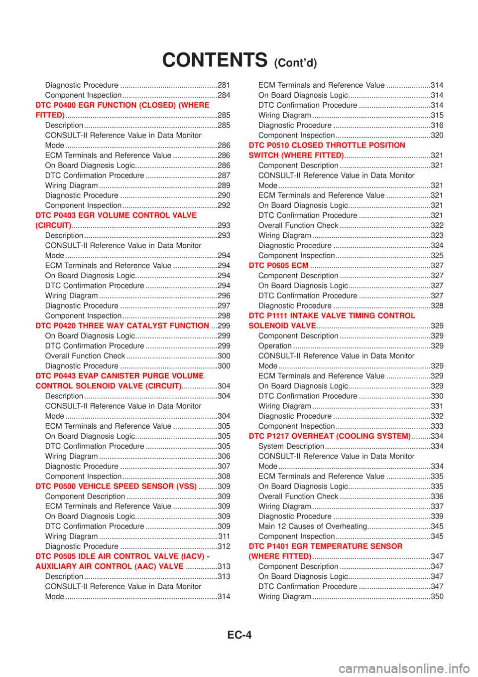
Diagnostic Procedure ..............................................281
Component Inspection .............................................284
DTC P0400 EGR FUNCTION (CLOSED) (WHERE
FITTED)........................................................................285
Description ...............................................................285
CONSULT-II Reference Value in Data Monitor
Mode ........................................................................286
ECM Terminals and Reference Value .....................286
On Board Diagnosis Logic.......................................286
DTC Confirmation Procedure ..................................287
Wiring Diagram ........................................................289
Diagnostic Procedure ..............................................290
Component Inspection .............................................292
DTC P0403 EGR VOLUME CONTROL VALVE
(CIRCUIT).....................................................................293
Description ...............................................................293
CONSULT-II Reference Value in Data Monitor
Mode ........................................................................294
ECM Terminals and Reference Value .....................294
On Board Diagnosis Logic.......................................294
DTC Confirmation Procedure ..................................294
Wiring Diagram ........................................................296
Diagnostic Procedure ..............................................297
Component Inspection .............................................298
DTC P0420 THREE WAY CATALYST FUNCTION...299
On Board Diagnosis Logic.......................................299
DTC Confirmation Procedure ..................................299
Overall Function Check ...........................................300
Diagnostic Procedure ..............................................300
DTC P0443 EVAP CANISTER PURGE VOLUME
CONTROL SOLENOID VALVE (CIRCUIT).................304
Description ...............................................................304
CONSULT-II Reference Value in Data Monitor
Mode ........................................................................304
ECM Terminals and Reference Value .....................305
On Board Diagnosis Logic.......................................305
DTC Confirmation Procedure ..................................305
Wiring Diagram ........................................................306
Diagnostic Procedure ..............................................307
Component Inspection .............................................308
DTC P0500 VEHICLE SPEED SENSOR (VSS).........309
Component Description ...........................................309
ECM Terminals and Reference Value .....................309
On Board Diagnosis Logic.......................................309
DTC Confirmation Procedure ..................................309
Wiring Diagram ........................................................ 311
Diagnostic Procedure ..............................................312
DTC P0505 IDLE AIR CONTROL VALVE (IACV) -
AUXILIARY AIR CONTROL (AAC) VALVE...............313
Description ...............................................................313
CONSULT-II Reference Value in Data Monitor
Mode ........................................................................314ECM Terminals and Reference Value .....................314
On Board Diagnosis Logic.......................................314
DTC Confirmation Procedure ..................................314
Wiring Diagram ........................................................315
Diagnostic Procedure ..............................................316
Component Inspection .............................................320
DTC P0510 CLOSED THROTTLE POSITION
SWITCH (WHERE FITTED).........................................321
Component Description ...........................................321
CONSULT-II Reference Value in Data Monitor
Mode ........................................................................321
ECM Terminals and Reference Value .....................321
On Board Diagnosis Logic.......................................321
DTC Confirmation Procedure ..................................321
Overall Function Check ...........................................322
Wiring Diagram ........................................................323
Diagnostic Procedure ..............................................324
Component Inspection .............................................325
DTC P0605 ECM.........................................................327
Component Description ...........................................327
On Board Diagnosis Logic.......................................327
DTC Confirmation Procedure ..................................327
Diagnostic Procedure ..............................................328
D T C P 1111INTAKE VALVE TIMING CONTROL
SOLENOID VALVE......................................................329
Component Description ...........................................329
Operation .................................................................329
CONSULT-II Reference Value in Data Monitor
Mode ........................................................................329
ECM Terminals and Reference Value .....................329
On Board Diagnosis Logic.......................................329
DTC Confirmation Procedure ..................................330
Wiring Diagram ........................................................331
Diagnostic Procedure ..............................................332
Component Inspection .............................................333
DTC P1217 OVERHEAT (COOLING SYSTEM).........334
System Description ..................................................334
CONSULT-II Reference Value in Data Monitor
Mode ........................................................................334
ECM Terminals and Reference Value .....................335
On Board Diagnosis Logic.......................................335
Overall Function Check ...........................................336
Wiring Diagram ........................................................337
Diagnostic Procedure ..............................................339
Main 12 Causes of Overheating..............................345
Component Inspection .............................................345
DTC P1401 EGR TEMPERATURE SENSOR
(WHERE FITTED)........................................................347
Component Description ...........................................347
On Board Diagnosis Logic.......................................347
DTC Confirmation Procedure ..................................347
Wiring Diagram ........................................................350
CONTENTS(Cont'd)
EC-4