NISSAN ALMERA N16 2003 Electronic Repair Manual
Manufacturer: NISSAN, Model Year: 2003, Model line: ALMERA N16, Model: NISSAN ALMERA N16 2003Pages: 3189, PDF Size: 54.76 MB
Page 1101 of 3189
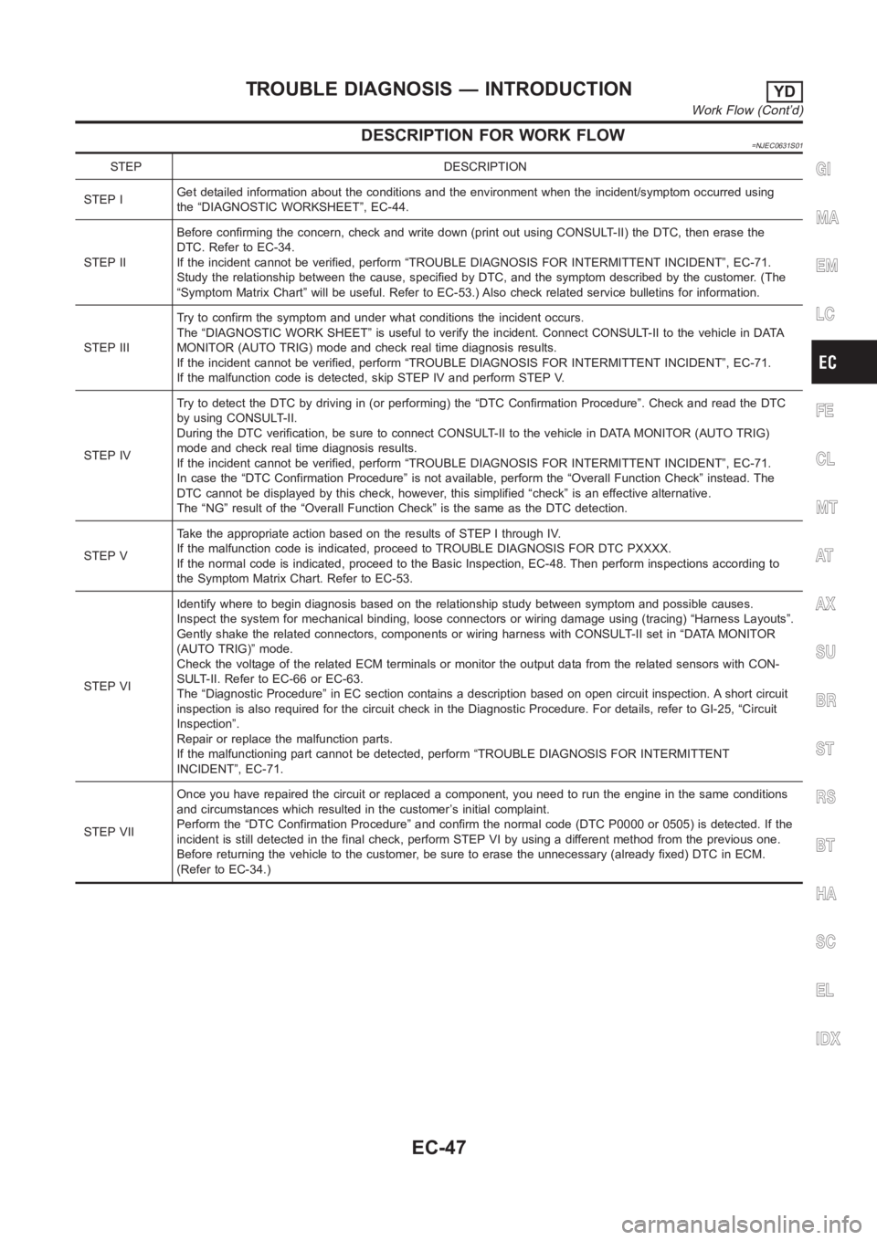
DESCRIPTION FOR WORK FLOW=NJEC0631S01
STEP DESCRIPTION
STEP IGet detailed information about the conditions and the environment when the incident/symptom occurred using
the “DIAGNOSTIC WORKSHEET”, EC-44.
STEP IIBefore confirming the concern, check and write down (print out using CONSULT-II) the DTC, then erase the
DTC. Refer to EC-34.
If the incident cannot be verified, perform “TROUBLE DIAGNOSIS FOR INTERMITTENT INCIDENT”, EC-71.
Study the relationship between the cause, specified by DTC, and the symptom described by the customer. (The
“Symptom Matrix Chart” will be useful. Refer to EC-53.) Also check relatedservice bulletins for information.
STEP IIITry to confirm the symptom and under what conditions the incident occurs.
The “DIAGNOSTIC WORK SHEET” is useful to verify the incident. Connect CONSULT-II to the vehicle in DATA
MONITOR (AUTO TRIG) mode and check real time diagnosis results.
If the incident cannot be verified, perform “TROUBLE DIAGNOSIS FOR INTERMITTENT INCIDENT”, EC-71.
If the malfunction code is detected, skip STEP IV and perform STEP V.
STEP IVTry to detect the DTC by driving in (or performing) the “DTC Confirmation Procedure”. Check and read the DTC
by using CONSULT-II.
During the DTC verification, be sure to connect CONSULT-II to the vehicle in DATA MONITOR (AUTO TRIG)
mode and check real time diagnosis results.
If the incident cannot be verified, perform “TROUBLE DIAGNOSIS FOR INTERMITTENT INCIDENT”, EC-71.
In case the “DTC Confirmation Procedure” is not available, perform the “Overall Function Check” instead. The
DTC cannot be displayed by this check, however, this simplified “check” isan effective alternative.
The “NG” result of the “Overall Function Check” is the same as the DTC detection.
STEP VTake the appropriate action based on the results of STEP I through IV.
If the malfunction code is indicated, proceed to TROUBLE DIAGNOSIS FOR DTCPXXXX.
If the normal code is indicated, proceed to the Basic Inspection, EC-48. Then perform inspections according to
the Symptom Matrix Chart. Refer to EC-53.
STEP VIIdentify where to begin diagnosis based on the relationship study betweensymptom and possible causes.
Inspect the system for mechanical binding, loose connectors or wiring damage using (tracing) “Harness Layouts”.
Gently shake the related connectors, components or wiring harness with CONSULT-II set in “DATA MONITOR
(AUTO TRIG)” mode.
Check the voltage of the related ECM terminals or monitor the output data from the related sensors with CON-
SULT-II. Refer to EC-66 or EC-63.
The “Diagnostic Procedure” in EC section contains a description based on open circuit inspection. A short circuit
inspection is also required for the circuit check in the Diagnostic Procedure. For details, refer to GI-25, “Circuit
Inspection”.
Repair or replace the malfunction parts.
If the malfunctioning part cannot be detected, perform “TROUBLE DIAGNOSIS FOR INTERMITTENT
INCIDENT”, EC-71.
STEP VIIOnce you have repaired the circuit or replaced a component, you need to run the engine in the same conditions
and circumstances which resulted in the customer’s initial complaint.
Perform the “DTC Confirmation Procedure” and confirm the normal code (DTCP0000 or 0505) is detected. If the
incident is still detected in the final check, perform STEP VI by using a different method from the previous one.
Before returning the vehicle to the customer, be sure to erase the unnecessary (already fixed) DTC in ECM.
(Refer to EC-34.)GI
MA
EM
LC
FE
CL
MT
AT
AX
SU
BR
ST
RS
BT
HA
SC
EL
IDX
TROUBLE DIAGNOSIS — INTRODUCTIONYD
Work Flow (Cont’d)
EC-47
Page 1102 of 3189
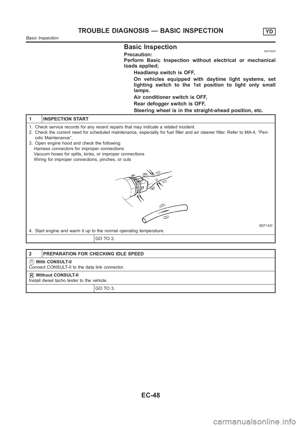
Basic InspectionNJEC0632Precaution:
Perform Basic Inspection without electrical or mechanical
loads applied;
Headlamp switch is OFF,
On vehicles equipped with daytime light systems, set
lighting switch to the 1st position to light only small
lamps.
Air conditioner switch is OFF,
Rear defogger switch is OFF,
Steering wheel is in the straight-ahead position, etc.
1 INSPECTION START
1. Check service records for any recent repairs that may indicate a relatedincident.
2. Check the current need for scheduled maintenance, especially for fuel filter and air cleaner filter. Refer to MA-4, “Peri-
odic Maintenance”.
3. Open engine hood and check the following:
Harness connectors for improper connections
Vacuum hoses for splits, kinks, or improper connections
Wiring for improper connections, pinches, or cuts
SEF142I
4. Start engine and warm it up to the normal operating temperature.
GO TO 2.
2 PREPARATION FOR CHECKING IDLE SPEED
With CONSULT-II
Connect CONSULT-II to the data link connector.
Without CONSULT-II
Install diesel tacho tester to the vehicle.
GO TO 3.
TROUBLE DIAGNOSIS — BASIC INSPECTIONYD
Basic Inspection
EC-48
Page 1103 of 3189
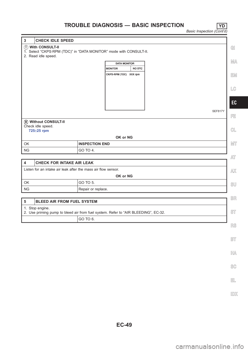
3 CHECK IDLE SPEED
With CONSULT-II
1. Select “CKPS·RPM (TDC)” in “DATA MONITOR” mode with CONSULT-II.
2. Read idle speed.
SEF817Y
Without CONSULT-II
Check idle speed.
725±25 rpm
OK or NG
OKINSPECTION END
NG GO TO 4.
4 CHECK FOR INTAKE AIR LEAK
Listen for an intake air leak after the mass air flow sensor.
OK or NG
OK GO TO 5.
NG Repair or replace.
5 BLEED AIR FROM FUEL SYSTEM
1. Stop engine.
2. Use priming pump to bleed air from fuel system. Refer to “AIR BLEEDING”, EC-32.
GO TO 6.
GI
MA
EM
LC
FE
CL
MT
AT
AX
SU
BR
ST
RS
BT
HA
SC
EL
IDX
TROUBLE DIAGNOSIS — BASIC INSPECTIONYD
Basic Inspection (Cont’d)
EC-49
Page 1104 of 3189
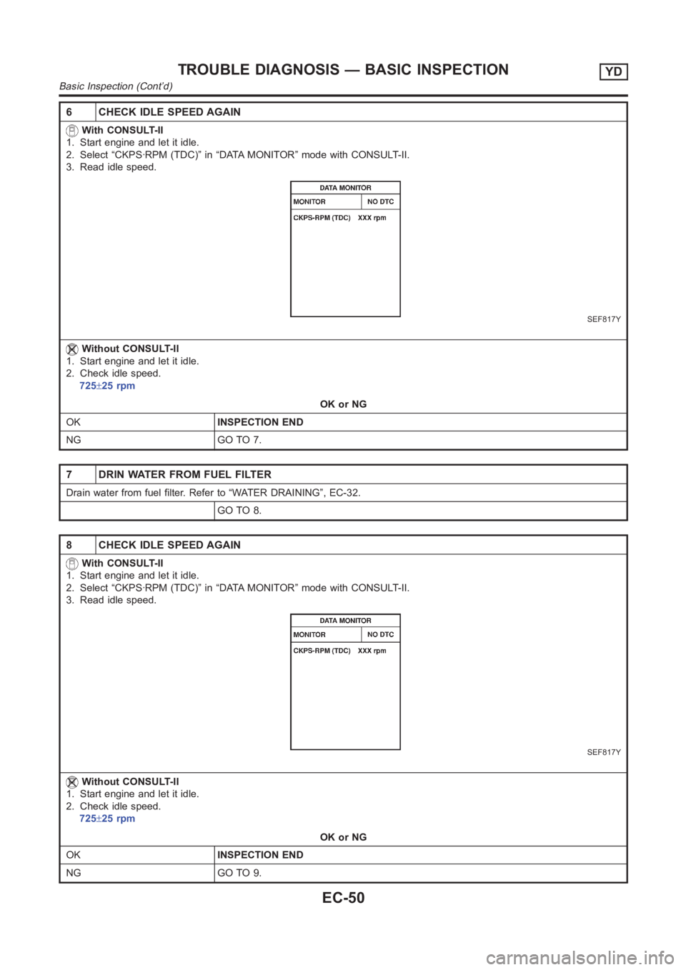
6 CHECK IDLE SPEED AGAIN
With CONSULT-II
1. Start engine and let it idle.
2. Select “CKPS·RPM (TDC)” in “DATA MONITOR” mode with CONSULT-II.
3. Read idle speed.
SEF817Y
Without CONSULT-II
1. Start engine and let it idle.
2. Check idle speed.
725±25 rpm
OK or NG
OKINSPECTION END
NG GO TO 7.
7 DRIN WATER FROM FUEL FILTER
Drain water from fuel filter. Refer to “WATER DRAINING”, EC-32.
GO TO 8.
8 CHECK IDLE SPEED AGAIN
With CONSULT-II
1. Start engine and let it idle.
2. Select “CKPS·RPM (TDC)” in “DATA MONITOR” mode with CONSULT-II.
3. Read idle speed.
SEF817Y
Without CONSULT-II
1. Start engine and let it idle.
2. Check idle speed.
725±25 rpm
OK or NG
OKINSPECTION END
NG GO TO 9.
TROUBLE DIAGNOSIS — BASIC INSPECTIONYD
Basic Inspection (Cont’d)
EC-50
Page 1105 of 3189
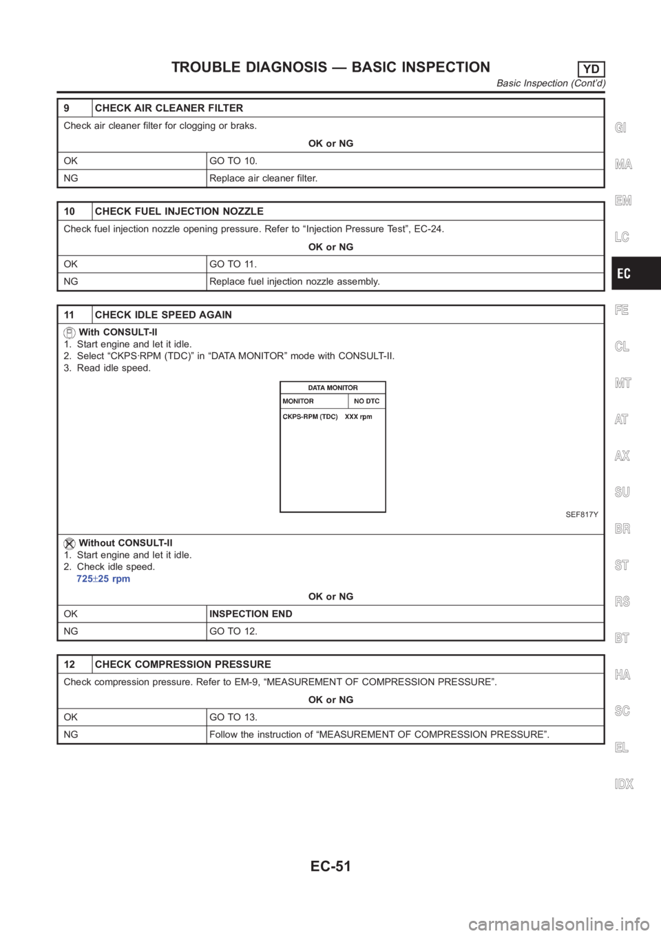
9 CHECK AIR CLEANER FILTER
Check air cleaner filter for clogging or braks.
OK or NG
OK GO TO 10.
NG Replace air cleaner filter.
10 CHECK FUEL INJECTION NOZZLE
Check fuel injection nozzle opening pressure. Refer to “Injection Pressure Test”, EC-24.
OK or NG
OK GO TO 11.
NG Replace fuel injection nozzle assembly.
11 CHECK IDLE SPEED AGAIN
With CONSULT-II
1. Start engine and let it idle.
2. Select “CKPS·RPM (TDC)” in “DATA MONITOR” mode with CONSULT-II.
3. Read idle speed.
SEF817Y
Without CONSULT-II
1. Start engine and let it idle.
2. Check idle speed.
725±25 rpm
OK or NG
OKINSPECTION END
NG GO TO 12.
12 CHECK COMPRESSION PRESSURE
Check compression pressure. Refer to EM-9, “MEASUREMENT OF COMPRESSION PRESSURE”.
OK or NG
OK GO TO 13.
NG Follow the instruction of “MEASUREMENT OF COMPRESSION PRESSURE”.
GI
MA
EM
LC
FE
CL
MT
AT
AX
SU
BR
ST
RS
BT
HA
SC
EL
IDX
TROUBLE DIAGNOSIS — BASIC INSPECTIONYD
Basic Inspection (Cont’d)
EC-51
Page 1106 of 3189
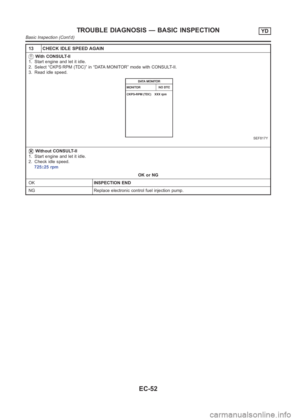
13 CHECK IDLE SPEED AGAIN
With CONSULT-II
1. Start engine and let it idle.
2. Select “CKPS·RPM (TDC)” in “DATA MONITOR” mode with CONSULT-II.
3. Read idle speed.
SEF817Y
Without CONSULT-II
1. Start engine and let it idle.
2. Check idle speed.
725±25 rpm
OK or NG
OKINSPECTION END
NG Replace electronic control fuel injection pump.
TROUBLE DIAGNOSIS — BASIC INSPECTIONYD
Basic Inspection (Cont’d)
EC-52
Page 1107 of 3189
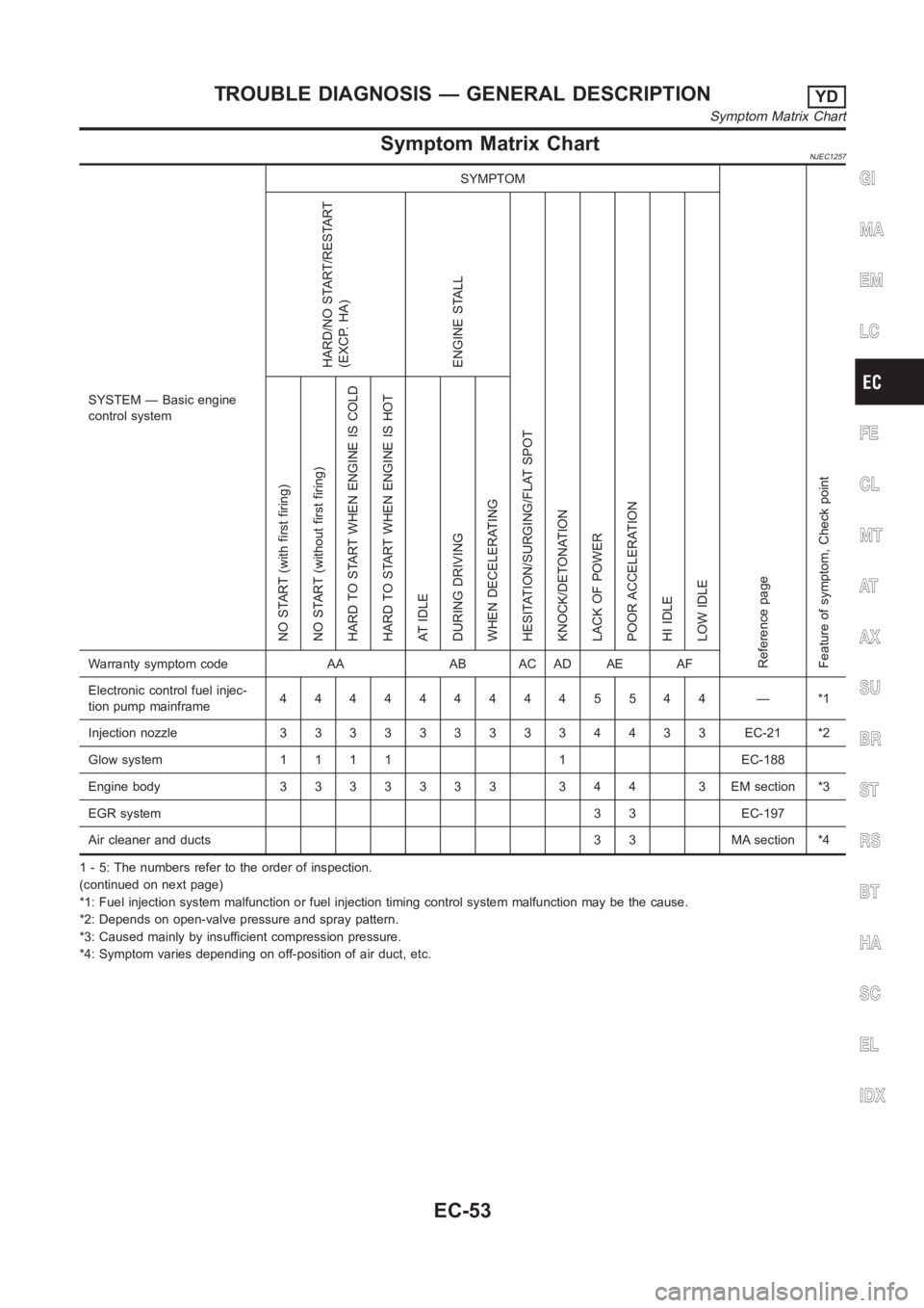
Symptom Matrix ChartNJEC1257
SYSTEM — Basic engine
control systemSYMPTOM
Reference page
Feature of symptom, Check pointHARD/NO START/RESTART
(EXCP. HA)
ENGINE STALL
HESITATION/SURGING/FLAT SPOT
KNOCK/DETONATION
LACK OF POWER
POOR ACCELERATION
HI IDLE
LOW IDLE NO START (with first firing)
NO START (without first firing)
HARD TO START WHEN ENGINE IS COLD
HARD TO START WHEN ENGINE IS HOT
AT IDLE
DURING DRIVING
WHEN DECELERATINGWarranty symptom code AA AB AC AD AE AF
Electronic control fuel injec-
tion pump mainframe4444444445544 — *1
Injection nozzle 3 3 3 3333334433 EC-21 *2
Glow system 1 1 1 1 1 EC-188
Engine body 3 3 3 3 3 3 3 3 4 4 3 EM section *3
EGR system3 3 EC-197
Air cleaner and ducts 3 3 MA section *4
1 - 5: The numbers refer to the order of inspection.
(continued on next page)
*1: Fuel injection system malfunction or fuel injection timing control system malfunction may be the cause.
*2: Depends on open-valve pressure and spray pattern.
*3: Caused mainly by insufficient compression pressure.
*4: Symptom varies depending on off-position of air duct, etc.
GI
MA
EM
LC
FE
CL
MT
AT
AX
SU
BR
ST
RS
BT
HA
SC
EL
IDX
TROUBLE DIAGNOSIS — GENERAL DESCRIPTIONYD
Symptom Matrix Chart
EC-53
Page 1108 of 3189
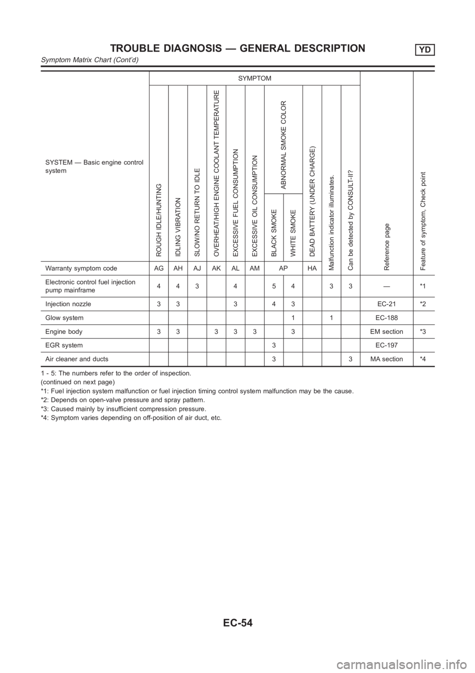
SYSTEM — Basic engine control
systemSYMPTOM
Reference page
Feature of symptom, Check pointROUGH IDLE/HUNTING
IDLING VIBRATION
SLOW/NO RETURN TO IDLE
OVERHEAT/HIGH ENGINE COOLANT TEMPERATURE
EXCESSIVE FUEL CONSUMPTION
EXCESSIVE OIL CONSUMPTION
ABNORMAL SMOKE COLOR
DEAD BATTERY (UNDER CHARGE)
Malfunction indicator illuminates.
Can be detected by CONSULT-II?BLACK SMOKE
WHITE SMOKEWarranty symptom code AG AH AJ AK AL AM AP HA
Electronic control fuel injection
pump mainframe44345433—*1
Injection nozzle 3 3 3 4 3 EC-21 *2
Glow system 1 1 EC-188
Engine body 3 3 3 3 3 3 EM section *3
EGR system 3 EC-197
Air cleaner and ducts 3 3 MA section *4
1 - 5: The numbers refer to the order of inspection.
(continued on next page)
*1: Fuel injection system malfunction or fuel injection timing control system malfunction may be the cause.
*2: Depends on open-valve pressure and spray pattern.
*3: Caused mainly by insufficient compression pressure.
*4: Symptom varies depending on off-position of air duct, etc.
TROUBLE DIAGNOSIS — GENERAL DESCRIPTIONYD
Symptom Matrix Chart (Cont’d)
EC-54
Page 1109 of 3189
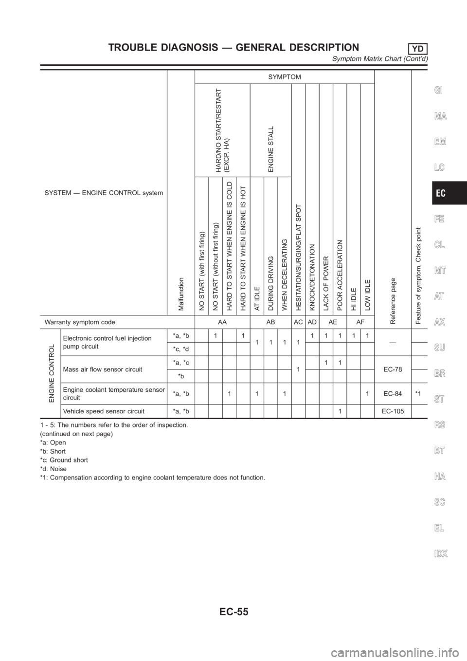
SYSTEM — ENGINE CONTROL system
Malfunction
SYMPTOM
Reference page
Feature of symptom, Check pointHARD/NO START/RESTART
(EXCP. HA)
ENGINE STALL
HESITATION/SURGING/FLAT SPOT
KNOCK/DETONATION
LACK OF POWER
POOR ACCELERATION
HI IDLE
LOW IDLE NO START (with first firing)
NO START (without first firing)
HARD TO START WHEN ENGINE IS COLD
HARD TO START WHEN ENGINE IS HOT
AT IDLE
DURING DRIVING
WHEN DECELERATINGWarranty symptom code AA AB AC AD AE AF
ENGINE CONTROL
Electronic control fuel injection
pump circuit*a, *b 1 1
111111111
—
*c, *d
Mass air flow sensor circuit*a, *c
111
EC-78
*b
Engine coolant temperature sensor
circuit*a, *b 1 1 1 1 EC-84 *1
Vehicle speed sensor circuit *a, *b 1 EC-105
1 - 5: The numbers refer to the order of inspection.
(continued on next page)
*a: Open
*b: Short
*c: Ground short
*d: Noise
*1: Compensation according to engine coolant temperature does not function.
GI
MA
EM
LC
FE
CL
MT
AT
AX
SU
BR
ST
RS
BT
HA
SC
EL
IDX
TROUBLE DIAGNOSIS — GENERAL DESCRIPTIONYD
Symptom Matrix Chart (Cont’d)
EC-55
Page 1110 of 3189
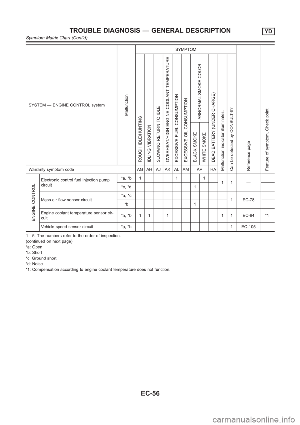
SYSTEM — ENGINE CONTROL system
Malfunction
SYMPTOM
Reference page
Feature of symptom, Check pointROUGH IDLE/HUNTING
IDLING VIBRATION
SLOW/NO RETURN TO IDLE
OVERHEAT/HIGH ENGINE COOLANT TEMPERATURE
EXCESSIVE FUEL CONSUMPTION
EXCESSIVE OIL CONSUMPTION
ABNORMAL SMOKE COLOR
DEAD BATTERY (UNDER CHARGE)
Malfunction indicator illuminates.
Can be detected by CONSULT-II?BLACK SMOKE
WHITE SMOKEWarranty symptom code AG AH AJ AK AL AM AP HA
ENGINE CONTROL
Electronic control fuel injection pump
circuit*a, *b 1 1 1
11 —
*c, *d 1
Mass air flow sensor circuit*a, *c
1 EC-78
*b 1
Engine coolant temperature sensor cir-
cuit*a, *b 1 1 1 1 1 EC-84 *1
Vehicle speed sensor circuit *a, *b 1 EC-105
1 - 5: The numbers refer to the order of inspection.
(continued on next page)
*a: Open
*b: Short
*c: Ground short
*d: Noise
*1: Compensation according to engine coolant temperature does not function.
TROUBLE DIAGNOSIS — GENERAL DESCRIPTIONYD
Symptom Matrix Chart (Cont’d)
EC-56