AUX NISSAN ALMERA N16 2003 Electronic User Guide
[x] Cancel search | Manufacturer: NISSAN, Model Year: 2003, Model line: ALMERA N16, Model: NISSAN ALMERA N16 2003Pages: 3189, PDF Size: 54.76 MB
Page 1484 of 3189
AT-28
OVERALL SYSTEM
TCM FUNCTION
The function of the TCM is to:
●Receive input signals sent from various switches and sensors.
●Determine required line pressure, shifting point, lock-up operation, and engine brake operation.
●Send required output signals to the respective solenoid valves.
INPUT/OUTPUT SIGNAL OF TCM
Control MechanismECS007NK
LINE PRESSURE CONTROL
TCM has various line pressure control characteristics to match the driving conditions.
An ON-OFF duty signal is sent to the line pressure solenoid valve based on TCM characteristics.
Hydraulic pressure on the clutch and brake is electronically controlled through the line pressure solenoid valve
to accommodate engine torque. This results in smooth shift operation.
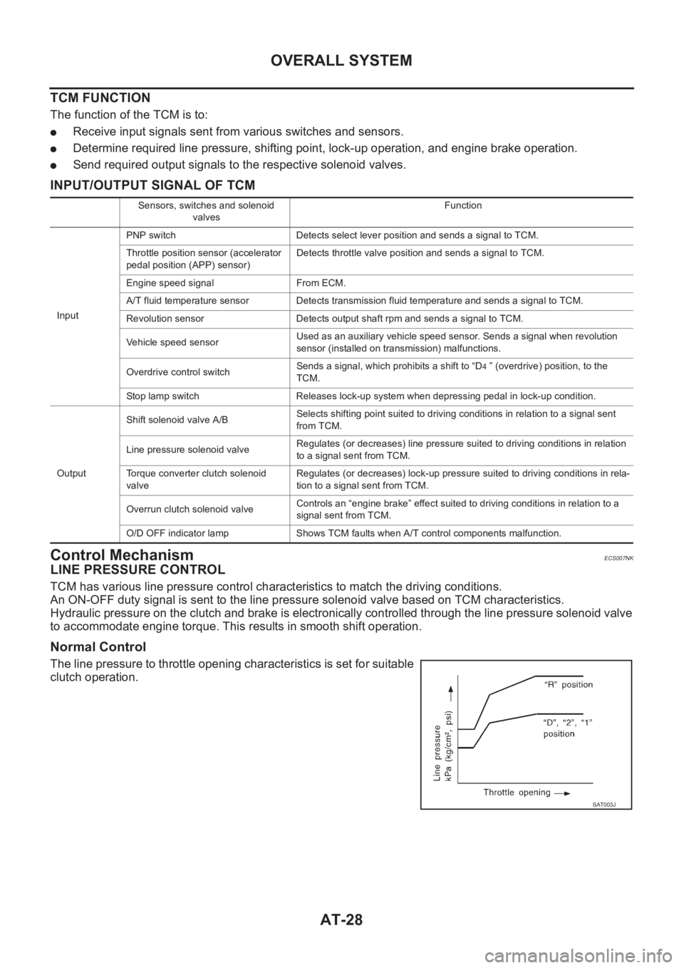
Normal Control
The line pressure to throttle opening characteristics is set for suitable
clutch operation.
Sensors, switches and solenoid
valvesFunction
InputPNP switch Detects select lever position and sends a signal to TCM.
Throttle position sensor (accelerator
pedal position (APP) sensor)Detects throttle valve position and sends a signal to TCM.
Engine speed signal From ECM.
A/T fluid temperature sensor Detects transmission fluid temperature and sends a signal to TCM.
Revolution sensor Detects output shaft rpm and sends a signal to TCM.
Vehicle speed sensorUsed as an auxiliary vehicle speed sensor. Sends a signal when revolution
sensor (installed on transmission) malfunctions.
Overdrive control switchSends a signal, which prohibits a shift to “D
4 ” (overdrive) position, to the
TCM.
Stop lamp switch Releases lock-up system when depressing pedal in lock-up condition.
OutputShift solenoid valve A/BSelects shifting point suited to driving conditions in relation to a signal sent
from TCM.
Line pressure solenoid valveRegulates (or decreases) line pressure suited to driving conditions in relation
to a signal sent from TCM.
Torque converter clutch solenoid
valveRegulates (or decreases) lock-up pressure suited to driving conditions in rela-
tion to a signal sent from TCM.
Overrun clutch solenoid valveControls an “engine brake” effect suited to driving conditions in relation to a
signal sent from TCM.
O/D OFF indicator lamp Shows TCM faults when A/T control components malfunction.
SAT003J
Page 1657 of 3189
![NISSAN ALMERA N16 2003 Electronic User Guide DTC VEHICLE SPEED SENSOR MTR
AT-201
[EURO-OBD]
D
E
F
G
H
I
J
K
L
MA
B
AT
DTC VEHICLE SPEED SENSOR MTRPFP:24814
DescriptionECS007PU
The vehicle speed sensor·MTR is built into the speedometer](/img/5/57350/w960_57350-1656.png "NISSAN ALMERA N16 2003 Electronic User Guide DTC VEHICLE SPEED SENSOR MTR
AT-201
[EURO-OBD]
D
E
F
G
H
I
J
K
L
MA
B
AT
DTC VEHICLE SPEED SENSOR MTRPFP:24814
DescriptionECS007PU
The vehicle speed sensor·MTR is built into the speedometer")
DTC VEHICLE SPEED SENSOR MTR
AT-201
[EURO-OBD]
D
E
F
G
H
I
J
K
L
MA
B
AT
DTC VEHICLE SPEED SENSOR MTRPFP:24814
DescriptionECS007PU
The vehicle speed sensor·MTR is built into the speedometer assembly. The sensor functions as an auxiliary
device to the revolution sensor when it is malfunctioning. The TCM will then use a signal sent from the vehicle
speed sensor·MTR.
TCM TERMINALS AND REFERENCE VALUE
Remarks: Specification data are reference values.
ON BOARD DIAGNOSIS LOGIC
DIAGNOSTIC TROUBLE CODE (DTC) CONFIRMATION PROCEDURE
CAUTION:
●Always drive vehicle at a safe speed.
●If conducting this “DTC CONFIRMATION PROCEDURE” again, always turn ignition switch “OFF”
and wait at least 5 seconds before continuing.
After the repair, perform the following procedure to confirm the malfunction is eliminated.
With CONSULT-II
1. Turn ignition switch “ON” and select “DATA MONITOR” mode for
“A/T” with CONSULT-II.
2. Start engine and accelerate vehicle from 0 to 25 km/h (0 to 16
MPH).
3. If DTC is detected, go to AT- 2 0 4 , "
Diagnostic Procedure" .
Te r m i -
nal No.Wire color Item ConditionJudgement stan-
dard
(Approx.)
40 L/BVehicle speed
sensorWhen moving vehicle at 2 to 3 km/h
(1 to 2 MPH) for 1 m (3 ft) or more.Voltage varies
between 0V and
more than 4.5V
Diagnostic trouble code Malfunction is detected when... Check items (Possible cause)
: VHCL SPEED SEN·MTR
TCM does not receive the proper voltage
signal from the sensor.
●Harness or connectors
(The sensor circuit is open or shorted.)
●Vehicle speed sensor
: 2nd judgement flicker
SAT014K
SAT971J
Page 1804 of 3189
![NISSAN ALMERA N16 2003 Electronic User Guide AT-348
[ALL]
DTC VEHICLE SPEED SENSOR MTR
DTC VEHICLE SPEED SENSOR MTR
PFP:24814
DescriptionECS007RQ
The vehicle speed sensor·MTR is built into the speedometer assembly. The sensor functions](/img/5/57350/w960_57350-1803.png "NISSAN ALMERA N16 2003 Electronic User Guide AT-348
[ALL]
DTC VEHICLE SPEED SENSOR MTR
DTC VEHICLE SPEED SENSOR MTR
PFP:24814
DescriptionECS007RQ
The vehicle speed sensor·MTR is built into the speedometer assembly. The sensor functions")
AT-348
[ALL]
DTC VEHICLE SPEED SENSOR MTR
DTC VEHICLE SPEED SENSOR MTR
PFP:24814
DescriptionECS007RQ
The vehicle speed sensor·MTR is built into the speedometer assembly. The sensor functions as an auxiliary
device to the revolution sensor when it is malfunctioning. The TCM will then use a signal sent from the vehicle
speed sensor·MTR.
TCM TERMINALS AND REFERENCE VALUE
Remarks: Specification data are reference values.
ON BOARD DIAGNOSIS LOGIC
SELF-DIAGNOSIS CODE CONFIRMATION PROCEDURE
After the repair, perform the following procedure to confirm the malfunction is eliminated.
With CONSULT-II
1. Start engine.
2. Select “SELF-DIAG RESULTS” mode for A/T with CONSULT-II.
3. Drive vehicle under the following conditions:
Selector lever in “D” position and vehicle speed higher than 20
km/h (12 MPH).
4. If DTC is detected, go to AT- 3 5 1 , "
Diagnostic Procedure" .
Te r m i -
nal No.Wire color Item ConditionJudgement stan-
dard
(Approx.)
40 L/BVehicle speed
sensorWhen moving vehicle at 2 to 3 km/h
(1 to 2 MPH) for 1 m (3 ft) or more.Voltage varies
between less
than 0V and
more than 4.5V
Diagnostic trouble code Malfunction is detected when... Check items (Possible cause)
: VHCL SPEED SEN·MTR
TCM does not receive the proper voltage
signal from the sensor.
●Harness or connectors
(The sensor circuit is open or shorted.)
●Vehicle speed sensor
: 2nd judgement flicker
SAT014K
SAT971J
Page 1982 of 3189
ATC-2
Discharge Air Flow ................................................. 27
System Description ................................................. 28
SWITCHES AND THEIR CONTROL FUNCTION ... 28
TROUBLE DIAGNOSIS ............................................ 29
How to Perform Trouble Diagnoses for Quick and
Accurate Repair ...................................................... 29
WORK FLOW ...................................................... 29
SYMPTOM TABLE .............................................. 29
Component Parts and Harness Connector Location ... 30
ENGINE COMPARTMENT .................................. 30
PASSENGER COMPARTMENT .......................... 31
Circuit Diagram ....................................................... 32
Wiring Diagram ....................................................... 33
Auto Amp. Terminals and Reference Value ............ 40
PIN CONNECTOR TERMINAL LAYOUT ............ 40
AUTO AMP. INSPECTION TABLE ...................... 40
Self-diagnosis Function .......................................... 42
DESCRIPTION .................................................... 42
FUNCTION CONFIRMATION PROCEDURE ...... 43
AUXILIARY MECHANISM: TEMPERATURE
SETTING TRIMMER ........................................... 49
Operational Check .................................................. 51
CHECKING MEMORY FUNCTION ..................... 51
CHECKING BLOWER ......................................... 51
CHECKING DISCHARGE AIR ............................ 52
CHECKING RECIRCULATION ............................ 53
CHECKING FRESH SWITCH ............................. 53
CHECKING TEMPERATURE DECREASE ......... 53
CHECKING TEMPERATURE INCREASE .......... 53
CHECKING AUTO MODE ................................... 54
Power Supply and Ground Circuit for Auto Amp. ... 55
INSPECTION FLOW ........................................... 55
COMPONENT DESCRIPTION ............................ 55
DIAGNOSTIC PROCEDURE FOR A/C SYSTEM ... 56
LAN System Circuit ............................................. ... 57
DIAGNOSTIC PROCEDURE FOR LAN SYS-
TEM CIRCUIT ..................................................... 57
Mode Door Motor Circuit ........................................ 59
INSPECTION FLOW ........................................... 60
SYSTEM DESCRIPTION .................................... 61
COMPONENT DESCRIPTION ............................ 62
DIAGNOSTIC PROCEDURE FOR MODE
DOOR .................................................................. 62
Air Mix Door Motor Circuit ...................................... 63
INSPECTION FLOW ........................................... 63
SYSTEM DESCRIPTION .................................... 64
COMPONENT DESCRIPTION ............................ 65
DIAGNOSTIC PROCEDURE FOR AIR MIX
DOOR MOTOR ................................................... 65
Intake Door Motor Circuit ........................................ 66
INSPECTION FLOW ........................................... 66
SYSTEM DESCRIPTION .................................
... 67
COMPONENT DESCRIPTION ............................ 67
DIAGNOSTIC PROCEDURE FOR INTAKE
DOOR MOTOR ................................................... 68
Blower Motor Circuit ............................................... 69
INSPECTION FLOW ........................................... 69
SYSTEM DESCRIPTION .................................... 70
COMPONENT DESCRIPTION ............................ 71DIAGNOSTIC PROCEDURE FOR BLOWER
MOTOR ................................................................ 71
COMPONENT INSPECTION ............................... 74
Magnet Clutch Circuit .............................................. 75
INSPECTION FLOW ............................................ 75
SYSTEM DESCRIPTION ..................................... 76
DIAGNOSTIC PROCEDURE FOR MAGNET
CLUTCH (WITH CAN SYSTEM) ......................... 76
DIAGNOSTIC PROCEDURE FOR MAGNET
CLUTCH (YD ENGINE WITHOUT COMMON
RAIL) .................................................................... 81
COMPONENT INSPECTION ............................... 85
Insufficient Cooling .................................................. 86
INSPECTION FLOW ............................................ 86
PERFORMANCE TEST DIAGNOSES ................ 88
PERFORMANCE CHART .................................... 90
TROUBLE DIAGNOSES FOR UNUSUAL PRES-
SURE ................................................................... 92
Insufficient Heating ................................................. 95
INSPECTION FLOW ............................................ 95
Noise ....................................................................... 97
INSPECTION FLOW ............................................ 97
Self-diagnosis ......................................................... 98
INSPECTION FLOW ............................................ 98
Memory Function .................................................... 99
INSPECTION FLOW ............................................ 99
Ambient Sensor Circuit .........................................100
COMPONENT DESCRIPTION ..........................100
AMBIENT TEMPERATURE INPUT PROCESS .100
DIAGNOSTIC PROCEDURE FOR AMBIENT
SENSOR ............................................................100
COMPONENT INSPECTION .............................102
In-vehicle Sensor Circuit .......................................102
COMPONENT DESCRIPTION ..........................102
DIAGNOSTIC PROCEDURE FOR IN-VEHICLE
SENSOR ............................................................103
COMPONENT INSPECTION .............................104
Sunload Sensor Circuit .........................................105
COMPONENT DESCRIPTION ..........................105
SUNLOAD INPUT PROCESS ...........................105
DIAGNOSTIC PROCEDURE FOR SUNLOAD
SENSOR ............................................................105
COMPONENT INSPECTION .............................107
Intake Sensor Circuit .............................................108
COMPONENT DESCRIPTION ..........................108
DIAGNOSTIC PROCEDURE FOR INTAKE SEN-
SOR ...................................................................108
Multiplex Communication Circuit ...........................109
DIAGNOSTIC PROCEDURE FOR MULTIPLEX
COMMUNICATION CIRCUIT ............................109
CONTROLLER ........................................................113
Removal and Installation .......................................113
AUTO AMP ..............................................................114
REMOVAL AND INSTALLATION ..........................114
AMBIENT SENSOR ................................................115
Removal and Installation .......................................115
IN-VEHICLE SENSOR ............................................116
Removal and Installation .......................................116
Page 2022 of 3189
ATC-42
TROUBLE DIAGNOSIS
Self-diagnosis Function
EJS001ZH
DESCRIPTION
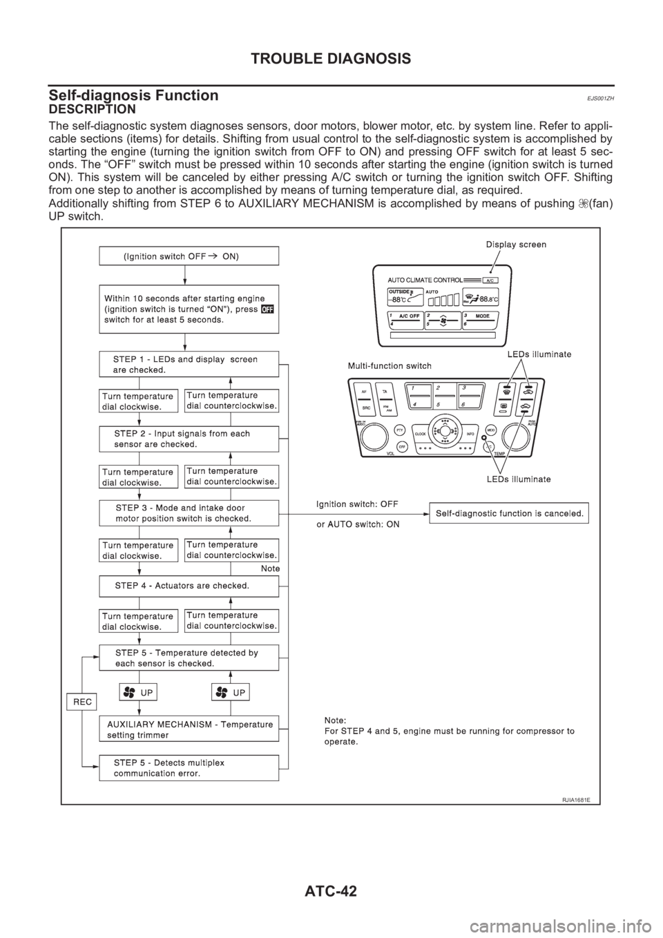
The self-diagnostic system diagnoses sensors, door motors, blower motor, etc. by system line. Refer to appli-
cable sections (items) for details. Shifting from usual control to the self-diagnostic system is accomplished by
starting the engine (turning the ignition switch from OFF to ON) and pressing OFF switch for at least 5 sec-
onds. The “OFF” switch must be pressed within 10 seconds after starting the engine (ignition switch is turned
ON). This system will be canceled by either pressing A/C switch or turning the ignition switch OFF. Shifting
from one step to another is accomplished by means of turning temperature dial, as required.
Additionally shifting from STEP 6 to AUXILIARY MECHANISM is accomplished by means of pushing (fan)
UP switch.
RJIA1681E
Page 2029 of 3189
TROUBLE DIAGNOSIS
ATC-49
C
D
E
F
G
H
I
K
L
MA
B
AT C
15.CHECK MALFUNCTIONING DOOR MOTOR POSITION SWITCH
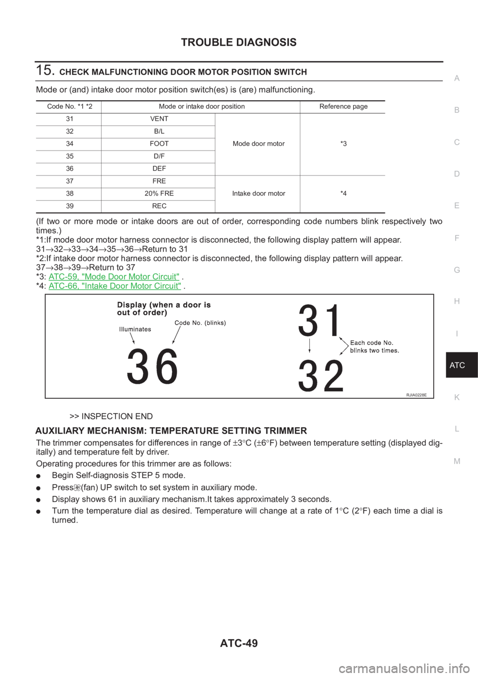
Mode or (and) intake door motor position switch(es) is (are) malfunctioning.
(If two or more mode or intake doors are out of order, corresponding code numbers blink respectively two
times.)
*1:If mode door motor harness connector is disconnected, the following display pattern will appear.
31→32→33→34→35→36→Return to 31
*2:If intake door motor harness connector is disconnected, the following display pattern will appear.
37→38→39→Return to 37
*3: AT C - 5 9 , "
Mode Door Motor Circuit" .
*4: AT C - 6 6 , "
Intake Door Motor Circuit" .
>> INSPECTION END
AUXILIARY MECHANISM: TEMPERATURE SETTING TRIMMER
The trimmer compensates for differences in range of ±3°C (±6°F) between temperature setting (displayed dig-
itally) and temperature felt by driver.
Operating procedures for this trimmer are as follows:
●Begin Self-diagnosis STEP 5 mode.
●Press (fan) UP switch to set system in auxiliary mode.
●Display shows 61 in auxiliary mechanism.It takes approximately 3 seconds.
●Turn the temperature dial as desired. Temperature will change at a rate of 1°C (2°F) each time a dial is
turned.
Code No. *1 *2 Mode or intake door position Reference page
31 VENT
Mode door motor *3 32 B/L
34 FOOT
35 D/F
36 DEF
37 FRE
Intake door motor *4 38 20% FRE
39 REC
RJIA0228E
Page 2549 of 3189
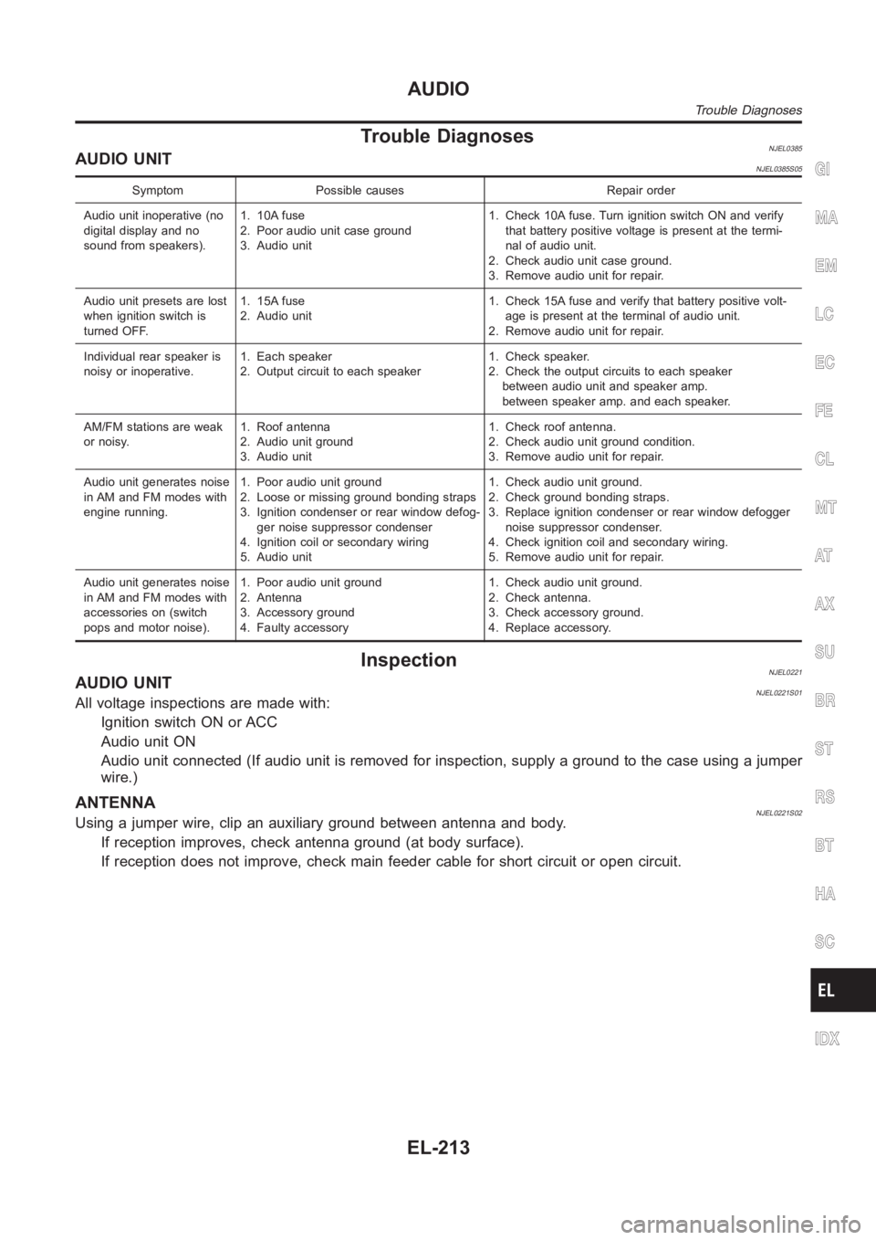
Trouble DiagnosesNJEL0385AUDIO UNITNJEL0385S05
Symptom Possible causes Repair order
Audio unit inoperative (no
digital display and no
sound from speakers).1. 10A fuse
2. Poor audio unit case ground
3. Audio unit1. Check 10A fuse. Turn ignition switch ON and verify
that battery positive voltage is present at the termi-
nal of audio unit.
2. Check audio unit case ground.
3. Remove audio unit for repair.
Audio unit presets are lost
when ignition switch is
turned OFF.1. 15A fuse
2. Audio unit1. Check 15A fuse and verify that battery positive volt-
age is present at the terminal of audio unit.
2. Remove audio unit for repair.
Individual rear speaker is
noisy or inoperative.1. Each speaker
2. Output circuit to each speaker1. Check speaker.
2. Check the output circuits to each speaker
between audio unit and speaker amp.
between speaker amp. and each speaker.
AM/FM stations are weak
or noisy.1. Roof antenna
2. Audio unit ground
3. Audio unit1. Check roof antenna.
2. Check audio unit ground condition.
3. Remove audio unit for repair.
Audio unit generates noise
in AM and FM modes with
engine running.1. Poor audio unit ground
2. Loose or missing ground bonding straps
3. Ignition condenser or rear window defog-
ger noise suppressor condenser
4. Ignition coil or secondary wiring
5. Audio unit1. Check audio unit ground.
2. Check ground bonding straps.
3. Replace ignition condenser or rear window defogger
noise suppressor condenser.
4. Check ignition coil and secondary wiring.
5. Remove audio unit for repair.
Audio unit generates noise
in AM and FM modes with
accessories on (switch
pops and motor noise).1. Poor audio unit ground
2. Antenna
3. Accessory ground
4. Faulty accessory1. Check audio unit ground.
2. Check antenna.
3. Check accessory ground.
4. Replace accessory.
InspectionNJEL0221AUDIO UNITNJEL0221S01All voltage inspections are made with:
Ignition switch ON or ACC
Audio unit ON
Audio unit connected (If audio unit is removed for inspection, supply a ground to the case using a jumper
wire.)
ANTENNANJEL0221S02Using a jumper wire, clip an auxiliary ground between antenna and body.
If reception improves, check antenna ground (at body surface).
If reception does not improve, check main feeder cable for short circuit oropen circuit.
GI
MA
EM
LC
EC
FE
CL
MT
AT
AX
SU
BR
ST
RS
BT
HA
SC
IDX
AUDIO
Trouble Diagnoses
EL-213