belt NISSAN ALMERA N16 2003 Electronic Owner's Guide
[x] Cancel search | Manufacturer: NISSAN, Model Year: 2003, Model line: ALMERA N16, Model: NISSAN ALMERA N16 2003Pages: 3189, PDF Size: 54.76 MB
Page 287 of 3189
SEM853F
Oil Pressure CheckNJLC0004WARNING:
Be careful not to burn yourself, as the engine and oil may
be hot.
For M/T models, put gearshift lever in Neutral “N” posi-
tion. For A/T models, put selector lever in Park “P” posi-
tion.
1. Check oil level.
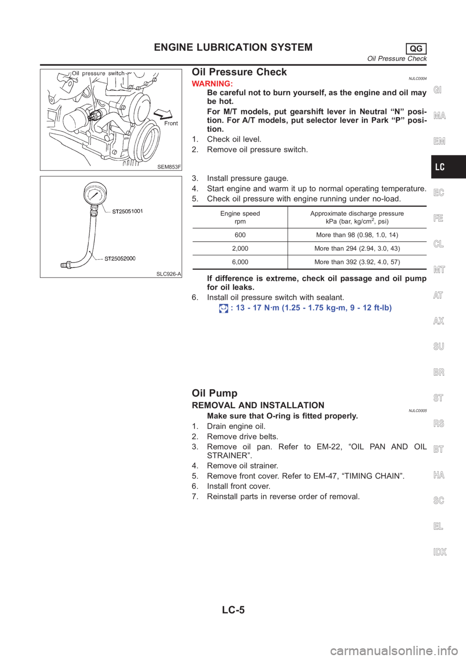
2. Remove oil pressure switch.
SLC926-A
3. Install pressure gauge.
4. Start engine and warm it up to normal operating temperature.
5. Check oil pressure with engine running under no-load.
Engine speed
rpmApproximate discharge pressure
kPa (bar, kg/cm2, psi)
600 More than 98 (0.98, 1.0, 14)
2,000 More than 294 (2.94, 3.0, 43)
6,000 More than 392 (3.92, 4.0, 57)
If difference is extreme, check oil passage and oil pump
for oil leaks.
6. Install oil pressure switch with sealant.
: 13 - 17 N·m (1.25 - 1.75 kg-m, 9 - 12 ft-lb)
Oil Pump
REMOVAL AND INSTALLATIONNJLC0005Make sure that O-ring is fitted properly.
1. Drain engine oil.
2. Remove drive belts.
3. Remove oil pan. Refer to EM-22, “OIL PAN AND OIL
STRAINER”.
4. Remove oil strainer.
5. Remove front cover. Refer to EM-47, “TIMING CHAIN”.
6. Install front cover.
7. Reinstall parts in reverse order of removal.
GI
MA
EM
EC
FE
CL
MT
AT
AX
SU
BR
ST
RS
BT
HA
SC
EL
IDX
ENGINE LUBRICATION SYSTEMQG
Oil Pressure Check
LC-5
Page 296 of 3189
Water Pump
REMOVAL AND INSTALLATIONNJLC0018
SEM858F
SEM859F
CAUTION:
When removing water pump assembly, be careful not to
get coolant on drive belt.
Water pump cannot be disassembled and should be
replaced as a unit.
After installing water pump, and check for leaks using
radiator cap tester.
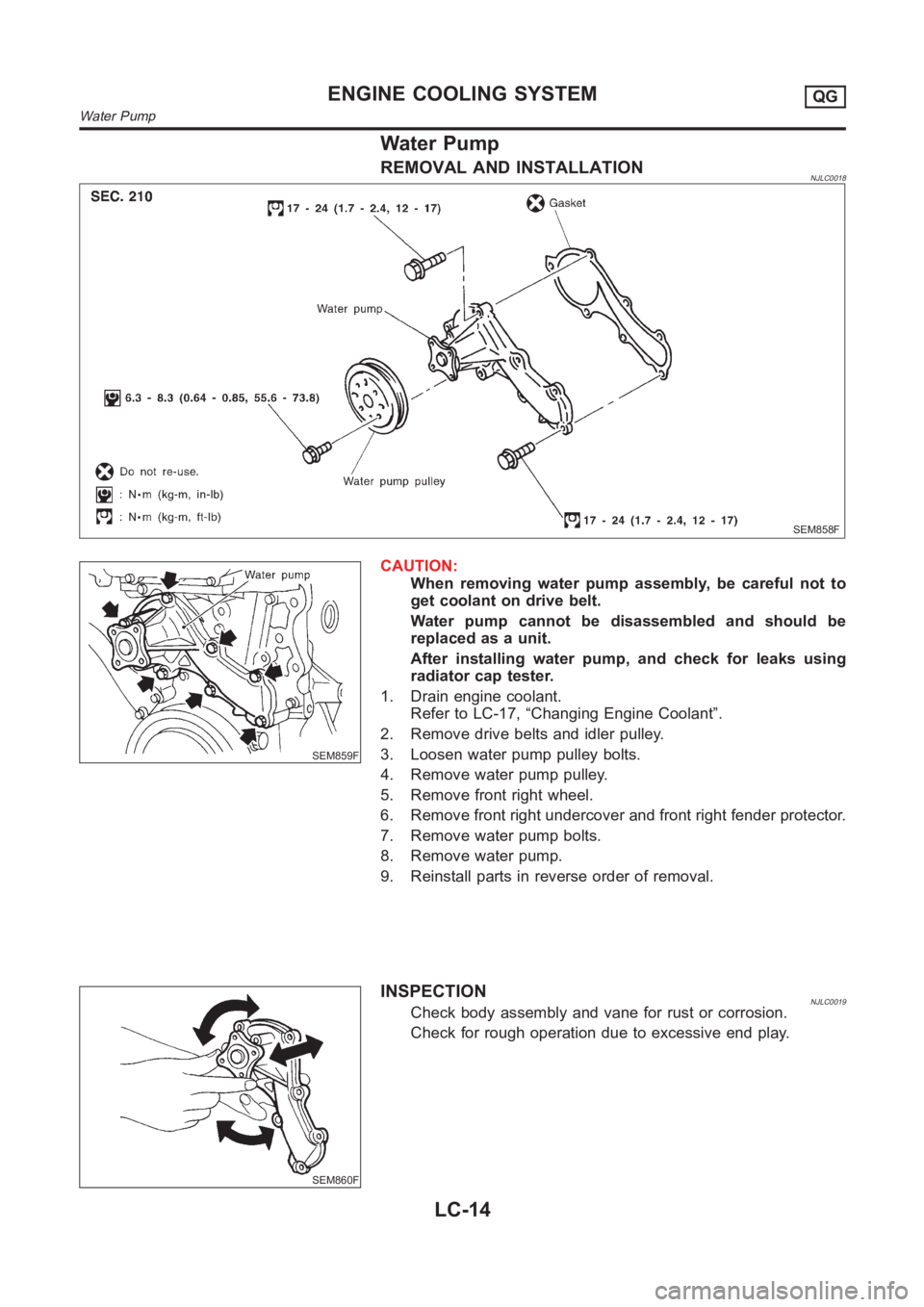
1. Drain engine coolant.
Refer to LC-17, “Changing Engine Coolant”.
2. Remove drive belts and idler pulley.
3. Loosen water pump pulley bolts.
4. Remove water pump pulley.
5. Remove front right wheel.
6. Remove front right undercover and front right fender protector.
7. Remove water pump bolts.
8. Remove water pump.
9. Reinstall parts in reverse order of removal.
SEM860F
INSPECTIONNJLC0019Check body assembly and vane for rust or corrosion.
Check for rough operation due to excessive end play.
ENGINE COOLING SYSTEMQG
Water Pump
LC-14
Page 300 of 3189
SMA033D
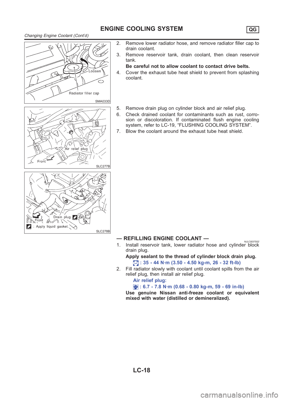
2. Remove lower radiator hose, and remove radiator filler cap to
drain coolant.
3. Remove reservoir tank, drain coolant, then clean reservoir
tank.
Be careful not to allow coolant to contact drive belts.
4. Cover the exhaust tube heat shield to prevent from splashing
coolant.
SLC277B
SLC278B
5. Remove drain plug on cylinder block and air relief plug.
6. Check drained coolant for contaminants such as rust, corro-
sion or discoloration. If contaminated flush engine cooling
system, refer to LC-19, “FLUSHING COOLING SYSTEM”.
7. Blow the coolant around the exhaust tube heat shield.
— REFILLING ENGINE COOLANT —NJLC0037S021. Install reservoir tank, lower radiator hose and cylinder block
drain plug.
Apply sealant to the thread of cylinder block drain plug.
: 35 - 44 N·m (3.50 - 4.50 kg-m, 26 - 32 ft-lb)
2. Fill radiator slowly with coolant until coolant spills from the air
relief plug, then install air relief plug.
Air relief plug:
: 6.7 - 7.8 N·m (0.68 - 0.80 kg-m, 59 - 69 in-lb)
Use genuine Nissan anti-freeze coolant or equivalent
mixed with water (distilled or demineralized).
ENGINE COOLING SYSTEMQG
Changing Engine Coolant (Cont’d)
LC-18
Page 305 of 3189
SLC934
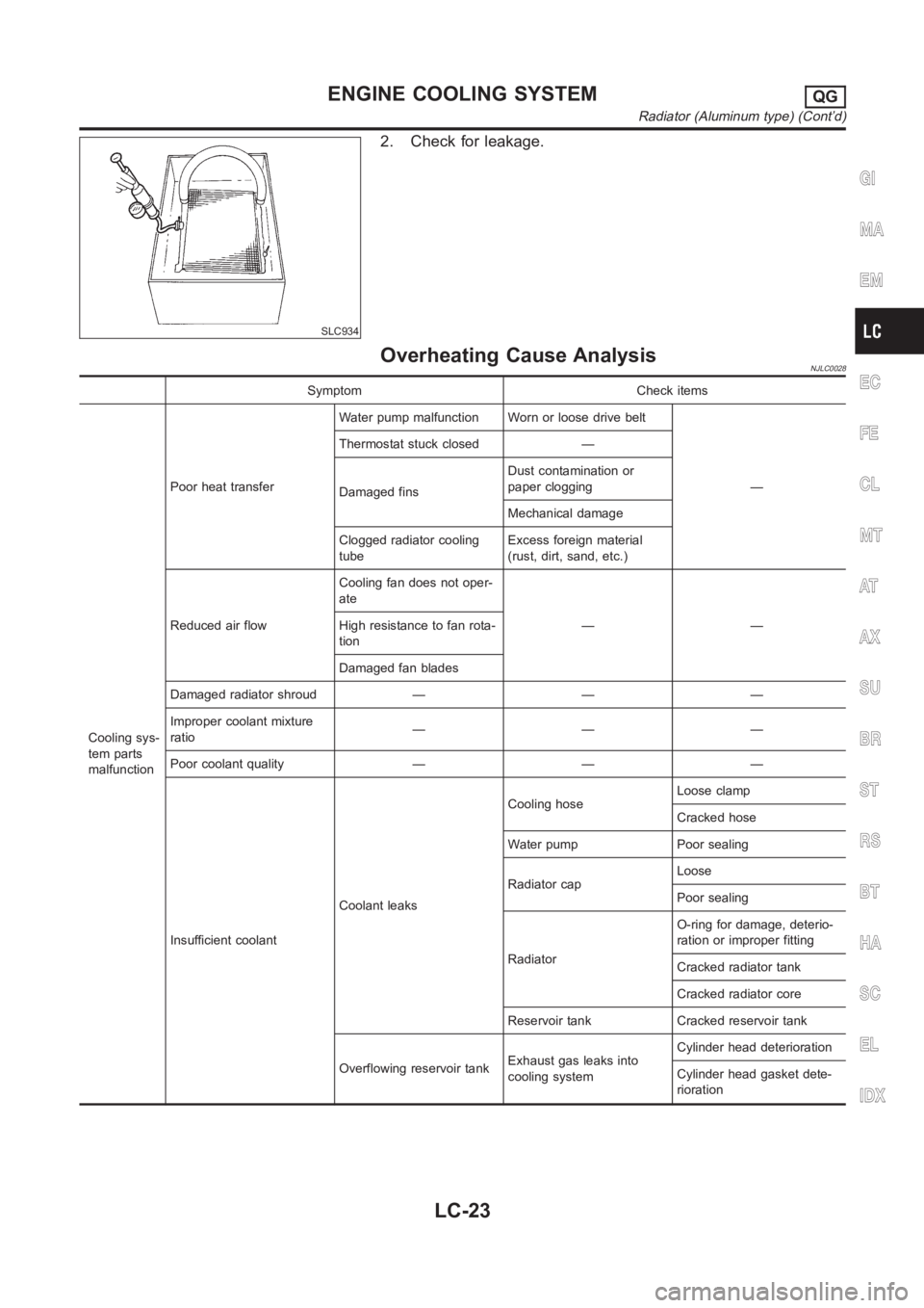
2. Check for leakage.
Overheating Cause AnalysisNJLC0028
Symptom Check items
Cooling sys-
tem parts
malfunctionPoor heat transferWater pump malfunction Worn or loose drive belt
— Thermostat stuck closed —
Damaged finsDust contamination or
paper clogging
Mechanical damage
Clogged radiator cooling
tubeExcess foreign material
(rust, dirt, sand, etc.)
Reduced air flowCooling fan does not oper-
ate
—— High resistance to fan rota-
tion
Damaged fan blades
Damaged radiator shroud — — —
Improper coolant mixture
ratio———
Poor coolant quality — — —
Insufficient coolantCoolant leaksCooling hoseLoose clamp
Cracked hose
Water pump Poor sealing
Radiator capLoose
Poor sealing
RadiatorO-ring for damage, deterio-
ration or improper fitting
Cracked radiator tank
Cracked radiator core
Reservoir tank Cracked reservoir tank
Overflowing reservoir tankExhaust gas leaks into
cooling systemCylinder head deterioration
Cylinder head gasket dete-
rioration
GI
MA
EM
EC
FE
CL
MT
AT
AX
SU
BR
ST
RS
BT
HA
SC
EL
IDX
ENGINE COOLING SYSTEMQG
Radiator (Aluminum type) (Cont’d)
LC-23
Page 320 of 3189
Replace the radiator cap if abnormalities are found with the
negative pressure valve, or if the valve opening pressure is out
of the standard range.
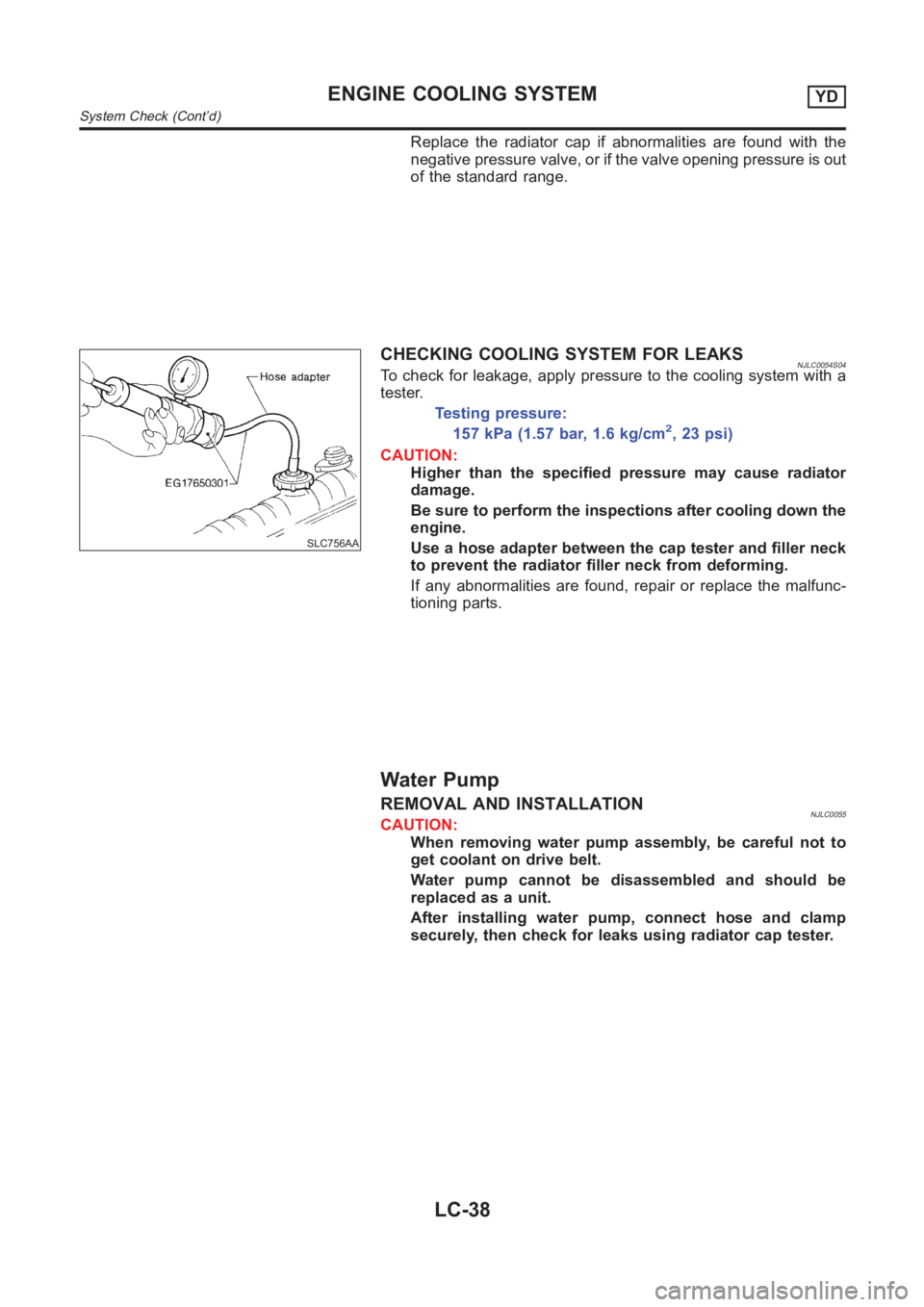
SLC756AA
CHECKING COOLING SYSTEM FOR LEAKSNJLC0054S04To check for leakage, apply pressure to the cooling system with a
tester.
Testing pressure:
157 kPa (1.57 bar, 1.6 kg/cm2,23psi)
CAUTION:
Higher than the specified pressure may cause radiator
damage.
Be sure to perform the inspections after cooling down the
engine.
Use a hose adapter between the cap tester and filler neck
to prevent the radiator filler neck from deforming.
If any abnormalities are found, repair or replace the malfunc-
tioning parts.
Water Pump
REMOVAL AND INSTALLATIONNJLC0055CAUTION:
When removing water pump assembly, be careful not to
get coolant on drive belt.
Water pump cannot be disassembled and should be
replaced as a unit.
After installing water pump, connect hose and clamp
securely, then check for leaks using radiator cap tester.
ENGINE COOLING SYSTEMYD
System Check (Cont’d)
LC-38
Page 321 of 3189
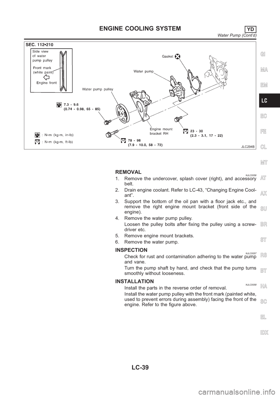
JLC294B
REMOVALNJLC00561. Remove the undercover, splash cover (right), and accessory
belt.
2. Drain engine coolant. Refer to LC-43, “Changing Engine Cool-
ant”.
3. Support the bottom of the oil pan with a floor jack etc., and
remove the right engine mount bracket (front side of the
engine).
4. Remove the water pump pulley.
Loosen the pulley bolts after fixing the pulley using a screw-
driver etc.
5. Remove engine mount brackets.
6. Remove the water pump.
INSPECTIONNJLC0057Check for rust and contamination adhering to the water pump
and vane.
Turn the pump shaft by hand, and check that the pump turns
smoothly without looseness.
INSTALLATIONNJLC0058Install the parts in the reverse order of removal.
Install the water pump pulley with the front mark (painted white,
used to prevent errors during assembly) facing the front of the
engine. Refer to the figure above.
GI
MA
EM
EC
FE
CL
MT
AT
AX
SU
BR
ST
RS
BT
HA
SC
EL
IDX
ENGINE COOLING SYSTEMYD
Water Pump (Cont’d)
LC-39
Page 325 of 3189
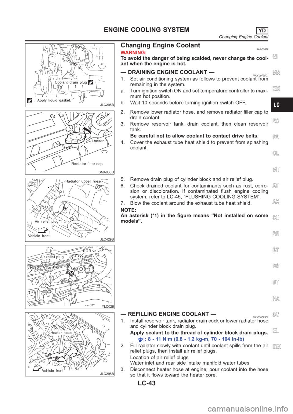
JLC295B
Changing Engine CoolantNJLC0079WARNING:
To avoid the danger of being scalded, never change the cool-
ant when the engine is hot.
— DRAINING ENGINE COOLANT —NJLC0079S011. Set air conditioning system as follows to prevent coolant from
remaining in the system.
a. Turn ignition switch ON and set temperature controller to maxi-
mum hot position.
b. Wait 10 seconds before turning ignition switch OFF.
SMA033D
2. Remove lower radiator hose, and remove radiator filler cap to
drain coolant.
3. Remove reservoir tank, drain coolant, then clean reservoir
tank.
Be careful not to allow coolant to contact drive belts.
4. Cover the exhaust tube heat shield to prevent from splashing
coolant.
JLC429B
YLC026
5. Remove drain plug of cylinder block and air relief plug.
6. Check drained coolant for contaminants such as rust, corro-
sion or discoloration. If contaminated flush engine cooling
system, refer to LC-45, “FLUSHING COOLING SYSTEM”.
7. Blow the coolant around the exhaust tube heat shield.
NOTE:
An asterisk (*1) in the figure means “Not installed on some
models”.
JLC298B
— REFILLING ENGINE COOLANT —NJLC0079S021. Install reservoir tank, radiator drain cock or lower radiator hose
and cylinder block drain plug.
Apply sealant to the thread of cylinder block drain plugs.
: 8 - 11 N·m (0.8 - 1.2 kg-m, 70 - 104 in-lb)
2. Fill radiator slowly with coolant until coolant spills from the air
relief plugs, then install air relief plugs.
Location of air relief plugs
Water inlet and rear side intake manifold water tubes
3. Disconnect heater hose at engine, pour coolant into the hose
so that it flows toward the heater core.
GI
MA
EM
EC
FE
CL
MT
AT
AX
SU
BR
ST
RS
BT
HA
SC
EL
IDX
ENGINE COOLING SYSTEMYD
Changing Engine Coolant
LC-43
Page 328 of 3189
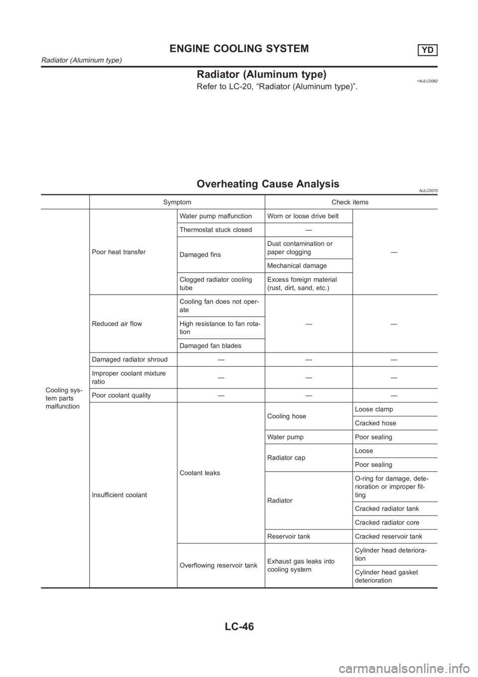
Radiator (Aluminum type)=NJLC0082Refer to LC-20, “Radiator (Aluminum type)”.
Overheating Cause AnalysisNJLC0070
Symptom Check items
Cooling sys-
tem parts
malfunctionPoor heat transferWater pump malfunction Worn or loose drive belt
— Thermostat stuck closed —
Damaged finsDust contamination or
paper clogging
Mechanical damage
Clogged radiator cooling
tubeExcess foreign material
(rust, dirt, sand, etc.)
Reduced air flowCooling fan does not oper-
ate
—— High resistance to fan rota-
tion
Damaged fan blades
Damaged radiator shroud — — —
Improper coolant mixture
ratio———
Poor coolant quality — — —
Insufficient coolantCoolant leaksCooling hoseLoose clamp
Cracked hose
Water pump Poor sealing
Radiator capLoose
Poor sealing
RadiatorO-ring for damage, dete-
rioration or improper fit-
ting
Cracked radiator tank
Cracked radiator core
Reservoir tank Cracked reservoir tank
Overflowing reservoir tankExhaust gas leaks into
cooling systemCylinder head deteriora-
tion
Cylinder head gasket
deterioration
ENGINE COOLING SYSTEMYD
Radiator (Aluminum type)
LC-46
Page 331 of 3189
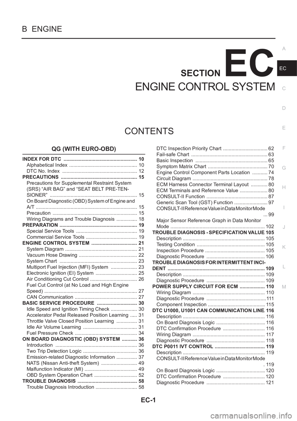
EC-1
ENGINE CONTROL SYSTEM
B ENGINE
CONTENTS
C
D
E
F
G
H
I
J
K
L
M
SECTION
A
EC
ENGINE CONTROL SYSTEM
QG (WITH EURO-OBD)
INDEX FOR DTC ...................................................... 10
Alphabetical Index .................................................. 10
DTC No. Index ....................................................... 12
PRECAUTIONS ........................................................ 15
Precautions for Supplemental Restraint System
(SRS) “AIR BAG” and “SEAT BELT PRE-TEN-
SIONER” ................................................................ 15
On Board Diagnostic (OBD) System of Engine and
A/T .......................................................................... 15
Precaution .............................................................. 15
Wiring Diagrams and Trouble Diagnosis ................ 18
PREPARATION ......................................................... 19
Special Service Tools ............................................. 19
Commercial Service Tools ...................................... 19
ENGINE CONTROL SYSTEM .................................. 21
System Diagram ..................................................... 21
Vacuum Hose Drawing ........................................... 22
System Chart ......................................................... 23
Multiport Fuel Injection (MFI) System .................... 23
Electronic Ignition (EI) System ............................... 25
Air Conditioning Cut Control ................................... 26
Fuel Cut Control (at No Load and High Engine
Speed) .................................................................... 27
CAN Communication .............................................. 27
BASIC SERVICE PROCEDURE .............................. 30
Idle Speed and Ignition Timing Check .................... 30
Accelerator Pedal Released Position Learning ...... 31
Throttle Valve Closed Position Learning ................ 31
Idle Air Volume Learning ........................................ 31
Fuel Pressure Check .............................................. 34
ON BOARD DIAGNOSTIC (OBD) SYSTEM ............ 36
Introduction ............................................................ 36
Two Trip Detection Logic ........................................ 36
Emission-related Diagnostic Information ................ 37
NATS (Nissan Anti-theft System) ........................... 49
Malfunction Indicator (MI) ....................................... 49
OBD System Operation Chart ................................ 52
TROUBLE DIAGNOSIS ............................................ 58
Trouble Diagnosis Introduction ............................... 58DTC Inspection Priority Chart ................................. 62
Fail-safe Chart ........................................................ 63
Basic Inspection ..................................................... 65
Symptom Matrix Chart ............................................ 70
Engine Control Component Parts Location ............ 74
Circuit Diagram ....................................................... 78
ECM Harness Connector Terminal Layout ............. 80
ECM Terminals and Reference Value ..................
... 80
CONSULT-II Function ............................................. 87
Generic Scan Tool (GST) Function ......................... 97
CONSULT-II Reference Value in Data Monitor Mode
... 99
Major Sensor Reference Graph in Data Monitor
Mode .....................................................................102
TROUBLE DIAGNOSIS - SPECIFICATION VALUE .105
Description ............................................................105
Testing Condition ..................................................105
Inspection Procedure ............................................105
Diagnostic Procedure ...........................................106
TROUBLE DIAGNOSIS FOR INTERMITTENT INCI-
DENT .......................................................................109
Description ............................................................109
Diagnostic Procedure ...........................................109
POWER SUPPLY CIRCUIT FOR ECM ...................110
Wiring Diagram .....................................................110
Diagnostic Procedure ............................................111
Component Inspection ..........................................115
DTC U1000, U1001 CAN COMMUNICATION LINE .116
Description ............................................................116
On Board Diagnosis Logic ....................................116
DTC Confirmation Procedure ...............................116
Wiring Diagram .....................................................117
Diagnostic Procedure ...........................................118
DTC P0011 IVT CONTROL .....................................119
Description ............................................................119
CONSULT-II Reference Value in Data Monitor Mode
.119
On Board Diagnosis Logic ....................................120
DTC Confirmation Procedure ...............................120
Diagnostic Procedure ...........................................121
Page 335 of 3189
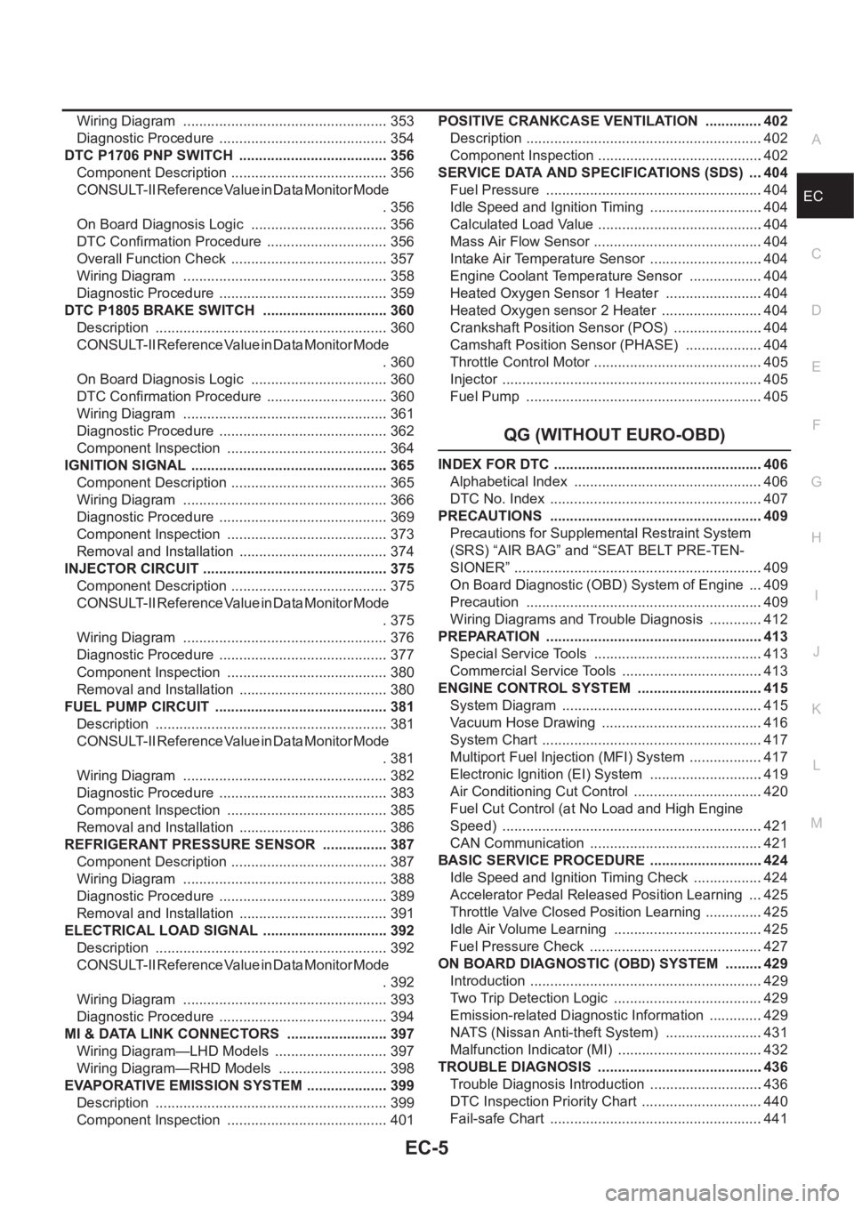
EC-5
C
D
E
F
G
H
I
J
K
L
M
ECA Wiring Diagram .................................................... 353
Diagnostic Procedure ........................................... 354
DTC P1706 PNP SWITCH ...................................... 356
Component Description ........................................ 356
CONSULT-II Reference Value in Data Monitor Mode
. 356
On Board Diagnosis Logic ................................... 356
DTC Confirmation Procedure ............................... 356
Overall Function Check ........................................ 357
Wiring Diagram .................................................... 358
Diagnostic Procedure ........................................... 359
DTC P1805 BRAKE SWITCH ................................ 360
Description ........................................................... 360
CONSULT-II Reference Value in Data Monitor Mode
. 360
On Board Diagnosis Logic ................................... 360
DTC Confirmation Procedure ............................... 360
Wiring Diagram .................................................... 361
Diagnostic Procedure ........................................... 362
Component Inspection ......................................... 364
IGNITION SIGNAL .................................................. 365
Component Description ........................................ 365
Wiring Diagram .................................................... 366
Diagnostic Procedure ........................................... 369
Component Inspection ......................................... 373
Removal and Installation ...................................... 374
INJECTOR CIRCUIT ............................................... 375
Component Description ........................................ 375
CONSULT-II Reference Value in Data Monitor Mode
. 375
Wiring Diagram .................................................... 376
Diagnostic Procedure ........................................... 377
Component Inspection ......................................... 380
Removal and Installation ...................................... 380
FUEL PUMP CIRCUIT ............................................ 381
Description ........................................................... 381
CONSULT-II Reference Value in Data Monitor Mode
. 381
Wiring Diagram .................................................... 382
Diagnostic Procedure ........................................... 383
Component Inspection ......................................... 385
Removal and Installation ...................................... 386
REFRIGERANT PRESSURE SENSOR ................. 387
Component Description ........................................ 387
Wiring Diagram .................................................... 388
Diagnostic Procedure ........................................... 389
Removal and Installation ...................................... 391
ELECTRICAL LOAD SIGNAL ................................ 392
Description ...................................................
........ 392
CONSULT-II Reference Value in Data Monitor Mode
. 392
Wiring Diagram .................................................... 393
Diagnostic Procedure ........................................... 394
MI & DATA LINK CONNECTORS .......................... 397
Wiring Diagram—LHD Models ............................. 397
Wiring Diagram—RHD Models ............................ 398
EVAPORATIVE EMISSION SYSTEM ..................... 399
Description ........................................................... 399
Component Inspection ......................................... 401POSITIVE CRANKCASE VENTILATION ...............402
Description ............................................................402
Component Inspection ..........................................402
SERVICE DATA AND SPECIFICATIONS (SDS) ....404
Fuel Pressure .......................................................404
Idle Speed and Ignition Timing .............................404
Calculated Load Value ..........................................404
Mass Air Flow Sensor ...........................................404
Intake Air Temperature Sensor .............................404
Engine Coolant Temperature Sensor ...................404
Heated Oxygen Sensor 1 Heater .........................404
Heated Oxygen sensor 2 Heater ..........................404
Crankshaft Position Sensor (POS) .......................404
Camshaft Position Sensor (PHASE) ....................404
Throttle Control Motor ...........................................405
Injector ..................................................................405
Fuel Pump ............................................................405
QG (WITHOUT EURO-OBD)
INDEX FOR DTC .....................................................406
Alphabetical Index ................................................406
DTC No. Index ......................................................407
PRECAUTIONS ......................................................409
Precautions for Supplemental Restraint System
(SRS) “AIR BAG” and “SEAT BELT PRE-TEN-
SIONER” ...............................................................409
On Board Diagnostic (OBD) System of Engine ....409
Precaution ............................................................409
Wiring Diagrams and Trouble Diagnosis ..............412
PREPARATION .......................................................413
Special Service Tools ...........................................413
Commercial Service Tools ....................................413
ENGINE CONTROL SYSTEM ................................415
System Diagram ...................................................415
Vacuum Hose Drawing .........................................416
System Chart ........................................................417
Multiport Fuel Injection (MFI) System ...................417
Electronic Ignition (EI) System .............................419
Air Conditioning Cut Control .................................420
Fuel Cut Control (at No Load and High Engine
Speed) ..................................................................421
CAN Communication ............................................421
BASIC SERVICE PROCEDURE .............................424
Idle Speed and Ignition Timing Check ..................424
Accelerator Pedal Released Position Learning ....425
Throttle Valve Closed Position Learning ...............425
Idle Air Volume Learning ......................................425
Fuel Pressure Check ............................................427
ON BOARD DIAGNOSTIC (OBD) SYSTEM ..........429
Introduction ...........................................................429
Two Trip Detection Logic ......................................429
Emission-related Diagnostic Information ..............429
NATS (Nissan Anti-theft System) .........................431
Malfunction Indicator (MI) .....................................432
TROUBLE DIAGNOSIS ..........................................436
Trouble Diagnosis Introduction .............................436
DTC Inspection Priority Chart ...............................440
Fail-safe Chart ......................................................441