overdrive NISSAN ALMERA N16 2003 Electronic Repair Manual
[x] Cancel search | Manufacturer: NISSAN, Model Year: 2003, Model line: ALMERA N16, Model: NISSAN ALMERA N16 2003Pages: 3189, PDF Size: 54.76 MB
Page 13 of 3189
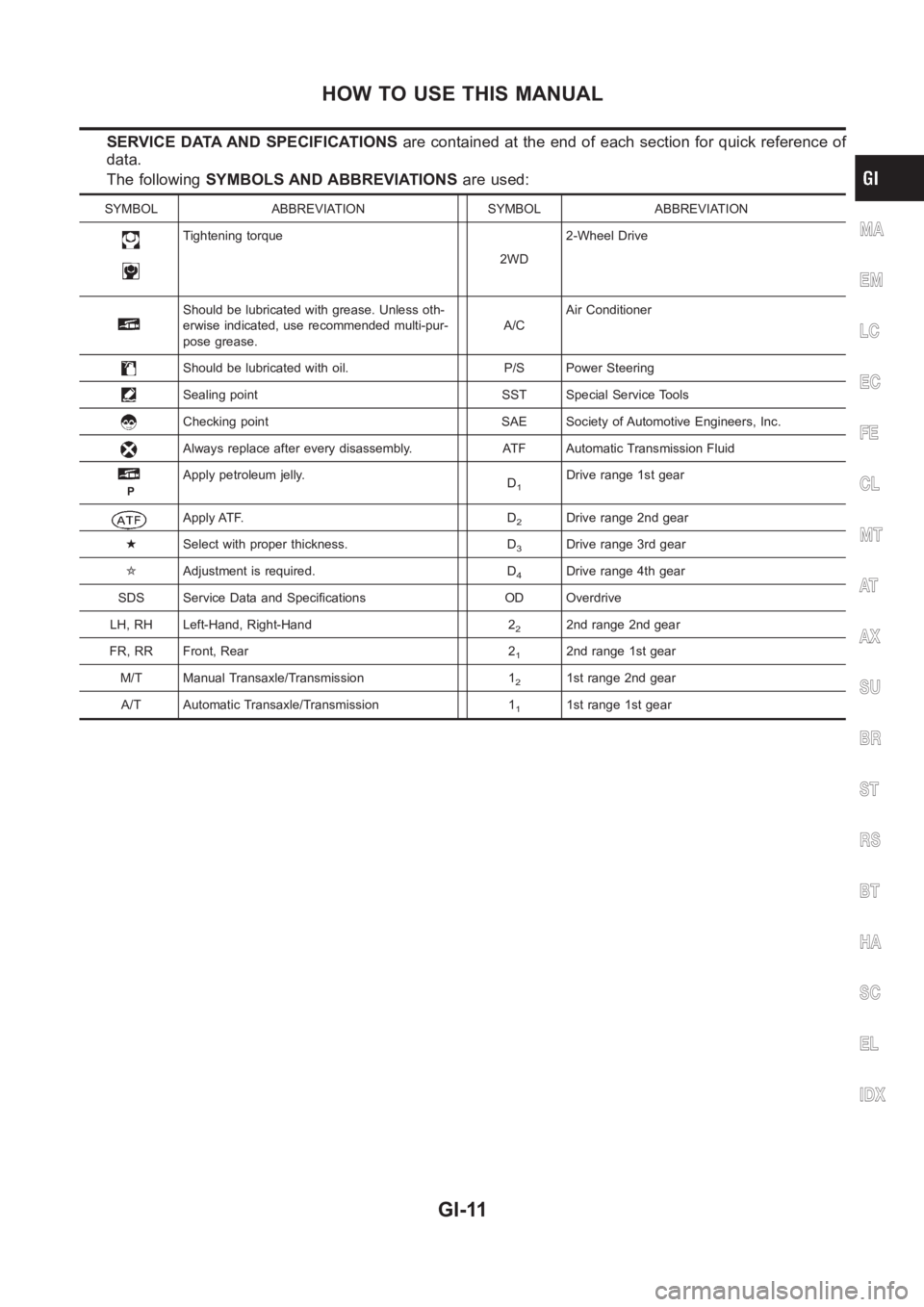
SERVICE DATA AND SPECIFICATIONSare contained at the end of each section for quick reference of
data.
The followingSYMBOLS AND ABBREVIATIONSare used:
SYMBOL ABBREVIATION SYMBOL ABBREVIATION
Tightening torque
2WD2-Wheel Drive
Should be lubricated with grease. Unless oth-
erwise indicated, use recommended multi-pur-
pose grease.A/CAir Conditioner
Should be lubricated with oil. P/S Power Steering
Sealing point SST Special Service Tools
Checking point SAE Society of Automotive Engineers, Inc.
Always replace after every disassembly. ATF Automatic Transmission Fluid
P
Apply petroleum jelly.
D1Drive range 1st gear
Apply ATF. D2Drive range 2nd gear
★Select with proper thickness. D
3Drive range 3rd gear
✩Adjustment is required. D
4Drive range 4th gear
SDS Service Data and Specifications OD Overdrive
LH, RH Left-Hand, Right-Hand 2
22nd range 2nd gear
FR, RR Front, Rear 2
12nd range 1st gear
M/T Manual Transaxle/Transmission 1
21st range 2nd gear
A/T Automatic Transaxle/Transmission 1
11st range 1st gear
MA
EM
LC
EC
FE
CL
MT
AT
AX
SU
BR
ST
RS
BT
HA
SC
EL
IDX
HOW TO USE THIS MANUAL
GI-11
Page 377 of 3189
![NISSAN ALMERA N16 2003 Electronic Repair Manual ON BOARD DIAGNOSTIC (OBD) SYSTEM
EC-47
[QG (WITH EURO-OBD)]
C
D
E
F
G
H
I
J
K
L
MA
EC
●The time required for each diagnosis varies with road surface conditions, weather, altitude, individual driv-
i NISSAN ALMERA N16 2003 Electronic Repair Manual ON BOARD DIAGNOSTIC (OBD) SYSTEM
EC-47
[QG (WITH EURO-OBD)]
C
D
E
F
G
H
I
J
K
L
MA
EC
●The time required for each diagnosis varies with road surface conditions, weather, altitude, individual driv-
i](/img/5/57350/w960_57350-376.png)
ON BOARD DIAGNOSTIC (OBD) SYSTEM
EC-47
[QG (WITH EURO-OBD)]
C
D
E
F
G
H
I
J
K
L
MA
EC
●The time required for each diagnosis varies with road surface conditions, weather, altitude, individual driv-
ing habits, etc.
Zone A refers to the range where the time, required for the diagnosis under normal conditions*, is the
shortest.
Zone B refers to the range where the diagnosis can still be performed if the diagnosis is not completed
within zone A.
*: Normal conditions refer to the following:
●Sea level
●Flat road
●Ambient air temperature: 20 - 30°C (68 - 86°F)
●Diagnosis is performed as quickly as possible under normal conditions.
Under different conditions [For example: ambient air temperature other than 20 - 30°C (68 - 86°F)], diag-
nosis may also be performed.
Pattern 1:
●The engine is started at the engine coolant temperature of −10 to 35°C (14 to 95°F)
(where the voltage between the ECM terminal 72 and ground is 3.0 - 4.3V).
●The engine must be operated at idle speed until the engine coolant temperature is greater than
70°C (158°F) (where the voltage between the ECM terminal 72 and ground is lower than 1.4V).
Pattern 2:
●When steady-state driving is performed again even after it is interrupted, each diagnosis can be con-
ducted. In this case, the time required for diagnosis may be extended.
*1: Depress the accelerator pedal until vehicle speed is 90 km/h (56 MPH), then release the accelerator pedal
and keep it released for more than 10 seconds. Depress the accelerator pedal until vehicle speed is 90 km/h
(56 MPH) again.
*2: Checking the vehicle speed with GST is advised.
Suggested Transmission Gear Position for A/T Models
Set the selector lever in the “D” position with the overdrive switch turned ON.
TEST VALUE AND TEST LIMIT (GST ONLY — NOT APPLICABLE TO CONSULT-II)
The following is the information specified in Mode 6 of ISO 15031-5.
The test value is a parameter used to determine whether a system/circuit diagnostic test is “OK” or “NG” while
being monitored by the ECM during self-diagnosis. The test limit is a reference value which is specified as the
maximum or minimum value and is compared with the test value being monitored.
Items for which these data (test value and test limit) are displayed are the same as SRT code items.
These data (test value and test limit) are specified by Test ID (TID) and Component ID (CID) and can be dis-
played on the GST screen.
×: Applicable —: Not applicable
SRT item Self-diagnostic test itemTest value (GST display)
Test limit Application
TID CID
CATALYST Three way catalyst function 01H 01H Max.×
HO2SHeated oxygen sensor 109H 04H Max.×
0AH 84H Min.×
0BH 04H Max.×
0CH 04H Max.×
0DH 04H Max.×
Heated oxygen sensor 219H 86H Min.×
1AH 86H Min.×
1BH 06H Max.×
1CH 06H Max.×
HO2S HTRHeated oxygen sensor 1 heater29H 08H Max.×
2AH 88H Min.×
Heated oxygen sensor 2 heater2DH 0AH Max.×
2EH 8AH Min.×
Page 1458 of 3189
AT-2
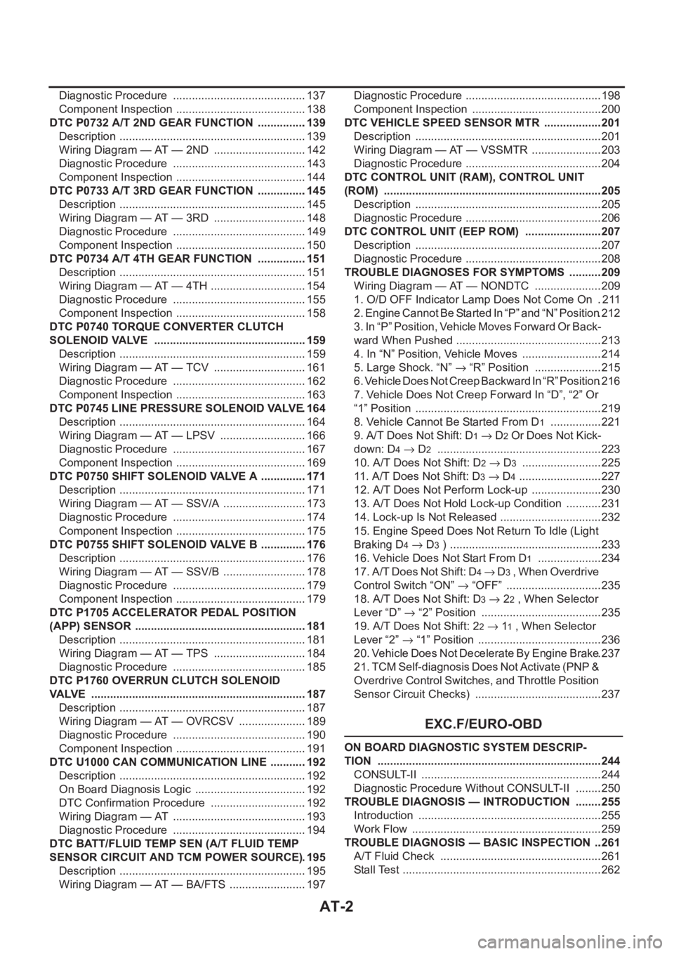
Diagnostic Procedure ...........................................137
Component Inspection ..........................................138
DTC P0732 A/T 2ND GEAR FUNCTION ................139
Description ............................................................139
Wiring Diagram — AT — 2ND ..............................142
Diagnostic Procedure ...........................................143
Component Inspection ..........................................144
DTC P0733 A/T 3RD GEAR FUNCTION ................145
Description ............................................................145
Wiring Diagram — AT — 3RD ..............................148
Diagnostic Procedure ...........................................149
Component Inspection ..........................................150
DTC P0734 A/T 4TH GEAR FUNCTION ................151
Description ............................................................151
Wiring Diagram — AT — 4TH ...............................154
Diagnostic Procedure ...........................................155
Component Inspection ..........................................158
DTC P0740 TORQUE CONVERTER CLUTCH
SOLENOID VALVE .................................................159
Description ............................................................159
Wiring Diagram — AT — TCV ..............................161
Diagnostic Procedure ...........................................162
Component Inspection ..........................................163
DTC P0745 LINE PRESSURE SOLENOID VALVE .164
Description ............................................................164
Wiring Diagram — AT — LPSV ............................166
Diagnostic Procedure ...........................................167
Component Inspection ..........................................169
DTC P0750 SHIFT SOLENOID VALVE A ...............171
Description ............................................................171
Wiring Diagram — AT — SSV/A ...........................173
Diagnostic Procedure ...........................................174
Component Inspection ..........................................175
DTC P0755 SHIFT SOLENOID VALVE B ...............176
Description ............................................................176
Wiring Diagram — AT — SSV/B ...........................178
Diagnostic Procedure ...........................................179
Component Inspection ..........................................179
DTC P1705 ACCELERATOR PEDAL POSITION
(APP) SENSOR .......................................................181
Description ............................................................181
Wiring Diagram — AT — TPS ..............................184
Diagnostic Procedure ...........................................185
DTC P1760 OVERRUN CLUTCH SOLENOID
VALVE .....................................................................187
Description ............................................................187
Wiring Diagram — AT — OVRCSV ......................189
Diagnostic Procedure ...........................................190
Component Inspection ..........................................191
DTC U1000 CAN COMMUNICATION LINE ............192
Description ............................................................192
On Board Diagnosis Logic ....................................192
DTC Confirmation Procedure ...............................192
Wiring Diagram — AT ...........................................193
Diagnostic Procedure ...........................................194
DTC BATT/FLUID TEMP SEN (A/T FLUID TEMP
SENSOR CIRCUIT AND TCM POWER SOURCE) .195
Description ............................................................195
Wiring Diagram — AT — BA/FTS .........................197Diagnostic Procedure ............................................198
Component Inspection ..........................................200
DTC VEHICLE SPEED SENSOR MTR ...................201
Description ............................................................201
Wiring Diagram — AT — VSSMTR .......................203
Diagnostic Procedure ............................................204
DTC CONTROL UNIT (RAM), CONTROL UNIT
(ROM) ......................................................................205
Description ............................................................205
Diagnostic Procedure ............................................206
DTC CONTROL UNIT (EEP ROM) .........................207
Description ............................................................207
Diagnostic Procedure ............................................208
TROUBLE DIAGNOSES FOR SYMPTOMS ...........209
Wiring Diagram — AT — NONDTC ......................209
1. O/D OFF Indicator Lamp Does Not Come On ..211
2. Engine Cannot Be Started In “P” and “N” Position .212
3. In “P” Position, Vehicle Moves Forward Or Back-
ward When Pushed ...............................................213
4. In “N” Position, Vehicle Moves ..........................214
5. Large Shock. “N” → “R” Position ......................215
6. Vehicle Does Not Creep Backward In “R” Position .216
7. Vehicle Does Not Creep Forward In “D”, “2” Or
“1” Position ............................................................219
8. Vehicle Cannot Be Started From D
1 .................221
9. A/T Does Not Shift: D
1→ D2 Or Does Not Kick-
down: D
4→ D2 .....................................................223
10. A/T Does Not Shift: D
2→ D3 ..........................225
11. A/T Does Not Shift: D
3→ D4 ...........................227
12. A/T Does Not Perform Lock-up .......................230
13. A/T Does Not Hold Lock-up Condition ............231
14. Lock-up Is Not Released .................................232
15. Engine Speed Does Not Return To Idle (Light
Braking D
4→ D3 ) .................................................233
16. Vehicle Does Not Start From D
1 .....................234
17. A/T Does Not Shift: D
4→ D3 , W h e n O v e r d r i v e
Control Switch “ON” → “OFF” ...............................235
18. A/T Does Not Shift: D
3→ 22 , When Selector
Lever “D” → “2” Position .......................................235
19. A/T Does Not Shift: 2
2→ 11 , When Selector
Lever “2” → “1” Position ........................................236
20. Vehicle Does Not Decelerate By Engine Brake .237
21. TCM Self-diagnosis Does Not Activate (PNP &
Overdrive Control Switches, and Throttle Position
Sensor Circuit Checks) .........................................237
EXC.F/EURO-OBD
ON BOARD DIAGNOSTIC SYSTEM DESCRIP-
TION ........................................................................244
CONSULT-II ..........................................................244
Diagnostic Procedure Without CONSULT-II .........250
TROUBLE DIAGNOSIS — INTRODUCTION .........255
Introduction ...........................................................255
Work Flow .............................................................259
TROUBLE DIAGNOSIS — BASIC INSPECTION ...261
A/T Fluid Check ....................................................261
Stall Test ................................................................262
Page 1459 of 3189
AT-3
D
E
F
G
H
I
J
K
L
MA
B
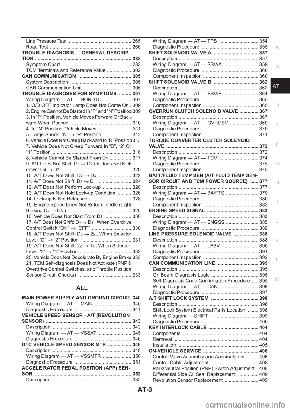
AT Line Pressure Test ............................................... 265
Road Test ............................................................. 266
TROUBLE DIAGNOSIS — GENERAL DESCRIP-
TION ........................................................................ 283
Symptom Chart .................................................... 283
TCM Terminals and Reference Value ................... 302
CAN COMMUNICATION ........................................ 305
System Description .............................................. 305
CAN Communication Unit .................................... 305
TROUBLE DIAGNOSES FOR SYMPTOMS .......... 307
Wiring Diagram — AT — NONDTC ...................... 307
1. O/D OFF Indicator Lamp Does Not Come On . 309
2. Engine Cannot Be Started In “P” and “N” Position . 309
3. In “P” Position, Vehicle Moves Forward Or Back-
ward When Pushed .............................................. 310
4. In “N” Position, Vehicle Moves .......................... 311
5. Large Shock. “N” → “R” Position ...................... 312
6. Vehicle Does Not Creep Backward In “R” Position . 313
7. Vehicle Does Not Creep Forward In “D”, “2” Or
“1” Position ........................................................... 316
8. Vehicle Cannot Be Started From D
1 ................. 317
9. A/T Does Not Shift: D
1→ D2 Or Does Not Kick
down: D
4→ D2 ..................................................... 320
10. A/T Does Not Shift: D
2→ D3 ......................... 322
11. A/T Does Not Shift: D
3→ D4 .......................... 324
12. A/T Does Not Perform Lock-up ...................... 326
13. A/T Does Not Hold Lock-up Condition ........... 326
14. Lock-up Is Not Released ................................ 328
15. Engine Speed Does Not Return To Idle (Light
Braking D
4→ D3 ) ................................................ 328
16. Vehicle Does Not Start From D
1 ..................... 330
17. A/T Does Not Shift: D
4→ D3 , When Overdrive
Control Switch “ON” → “OFF” .............................. 330
18. A/T Does Not Shift: D
3→ 22 , When Selector
Lever “D” → “2” Position ...................................... 331
19. A/T Does Not Shift: 2
2→ 11 , When Selector
Lever “2” → “1” Position ....................................... 332
20. Vehicle Does Not Decelerate By Engine Brake . 333
21. TCM Self-diagnosis Does Not Activate (PNP &
Overdrive Control Switches, and Throttle Position
Sensor Circuit Checks) ........................................ 333
ALL
MAIN POWER SUPPLY AND GROUND CIRCUIT . 340
Wiring Diagram — AT — MAIN ............................ 340
Diagnostic Procedure ........................................... 341
VEHICLE SPEED SENSOR - A/T (REVOLUTION
SENSOR) ................................................................ 343
Description ........................................................... 343
Wiring Diagram — AT — VSSAT ......................... 345
Diagnostic Procedure ........................................... 346
DTC VEHICLE SPEED SENSOR MTR .................. 348
Description ........................................................... 348
Wiring Diagram — AT — VSSMTR ...................... 350
Diagnostic Procedure ........................................... 351
ACCELE RATOR PEDAL POSITION (APP) SEN-
SOR ........................................................................ 352
Description ........................................................... 352Wiring Diagram — AT — TPS ..............................354
Diagnostic Procedure ...........................................355
SHIFT SOLENOID VALVE A ..................................357
Description ............................................................357
Wiring Diagram — AT — SSV/A ...........................359
Diagnostic Procedure ...........................................360
Component Inspection ..........................................360
SHIFT SOLENOID VALVE B ..................................362
Description ............................................................362
Wiring Diagram — AT — SSV/B ...........................364
Diagnostic Procedure ...........................................365
Component Inspection ..........................................365
OVERRUN CLUTCH SOLENOID VALVE ...............367
Description ............................................................367
Wiring Diagram — AT — OVRCSV ......................369
Diagnostic Procedure ...........................................370
Component Inspection ..........................................371
TORQUE CONVERTER CLUTCH SOLENOID
VALVE .....................................................................372
Description ............................................................372
Wiring Diagram — AT — TCV ..............................374
Diagnostic Procedure ...........................................375
Component Inspection ..........................................375
BATT/FLUID TEMP SEN (A/T FLUID TEMP SEN-
SOR CIRCUIT AND TCM POWER SOURCE) .......377
Description ............................................................377
Wiring Diagram — AT — BA/FTS .........................379
Diagnostic Procedure ...........................................380
Component Inspection ..........................................382
ENGINE SPEED SIGNAL .......................................383
Description ............................................................383
Wiring Diagram — AT — ENGSS .........................385
Diagnostic Procedure ...........................................386
LINE PRESSURE SOLENOID VALVE ...................388
Description ............................................................388
Wiring Diagram — AT — LPSV ............................390
Diagnostic Procedure ...........................................391
Component Inspection ..........................................393
CAN COMMUNICATION LINE ...............................395
Description ............................................................395
On Board Diagnosis Logic ....................................395
Self-Diagnosis Code Confirmation Procedure ......395
Wiring Diagram — AT — CAN ..............................396
Diagnostic Procedure ...........................................397
A/T SHIFT LOCK SYSTEM ....................................398
Description ............................................................398
Shift Lock System Electrical Parts Location .........398
Wiring Diagram — SHIFT — ................................399
Diagnostic Procedure ...........................................400
KEY INTERLOCK CABLE ......................................404
Components .........................................................404
Removal ...............................................................404
Installation ............................................................405
ON-VEHICLE SERVICE ..........................................406
Control Valve Assembly and Accumulators ..........406
Control Cable Adjustment .....................................408
Park/Neutral Position (PNP) Switch Adjustment ..408
Differential Side Oil Seal Replacement ................409
Revolution Sensor Replacement ..........................409
Page 1475 of 3189
OVERALL SYSTEM
AT-19
D
E
F
G
H
I
J
K
L
MA
B
AT
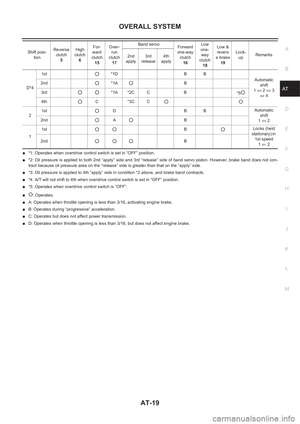
●*1: Operates when overdrive control switch is set in “OFF” position.
●*2: Oil pressure is applied to both 2nd “apply” side and 3rd “release” side of band servo piston. However, brake band does not con-
tract because oil pressure area on the “release” side is greater than that on the “apply” side.
●*3: Oil pressure is applied to 4th “apply” side in condition *2 above, and brake band contracts.
●*4: A/T will not shift to 4th when overdrive control switch is set in “OFF” position.
●*5: Operates when overdrive control switch is “OFF”.
●: Operates.
●A: Operates when throttle opening is less than 3/16, activating engine brake.
●B: Operates during “progressive” acceleration.
●C: Operates but does not affect power transmission.
●D: Operates when throttle opening is less than 3/16, but does not affect engine brake. D*41st *1D B B
Automatic
shift
1⇔ 2 ⇔ 3
⇔ 4 2nd *1A B
3rd *1A *2C C B
*5
4th C *3C C
21st D B BAutomatic
shift
1⇔ 2 2nd A B
11stBLocks (held
stationary) in
1st speed
1⇐ 2 2ndB Shift posi-
tionReverse
clutch
5High
clutch
6For-
ward
clutch
15Over-
run
clutch
17Band servo
Forward
one-way
clutch
16Low
one-
way
clutch
18Low &
revers
e brake
19Lock-
upRemarks
2nd
apply3rd
release4th
apply
Page 1478 of 3189
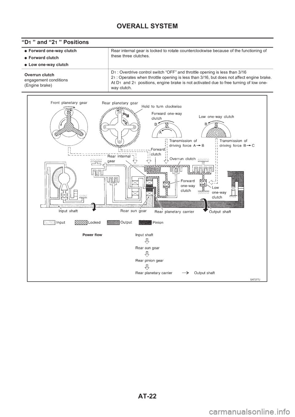
AT-22
OVERALL SYSTEM
“D1 ” and “21 ” Positions
●Forward one-way clutch
●Forward clutch
●Low one-way clutchRear internal gear is locked to rotate counterclockwise because of the functioning of
these three clutches.
Overrun clutch
engagement conditions
(Engine brake)D
1 : Overdrive control switch “OFF” and throttle opening is less than 3/16
2
1 : Operates when throttle opening is less than 3/16, but does not affect engine brake.
At D
1 and 21 positions, engine brake is not activated due to free turning of low one-
way clutch.
SAT377J
Page 1479 of 3189
OVERALL SYSTEM
AT-23
D
E
F
G
H
I
J
K
L
MA
B
AT
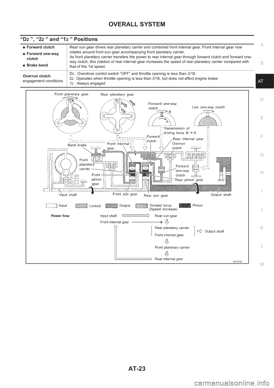
“D2 ”, “22 ” and “12 ” Positions
●Forward clutch
●Forward one-way
clutch
●Brake bandRear sun gear drives rear planetary carrier and combined front internal gear. Front internal gear now
rotates around front sun gear accompanying front planetary carrier.
As front planetary carrier transfers the power to rear internal gear through forward clutch and forward one-
way clutch, this rotation of rear internal gear increases the speed of rear planetary carrier compared with
that of the 1st speed.
Overrun clutch
engagement conditionsD
2 : Overdrive control switch “OFF” and throttle opening is less than 3/16
2
2: Operates when throttle opening is less than 3/16, but does not affect engine brake.
1
2 : Always engaged
SAT378J
Page 1480 of 3189
AT-24
OVERALL SYSTEM
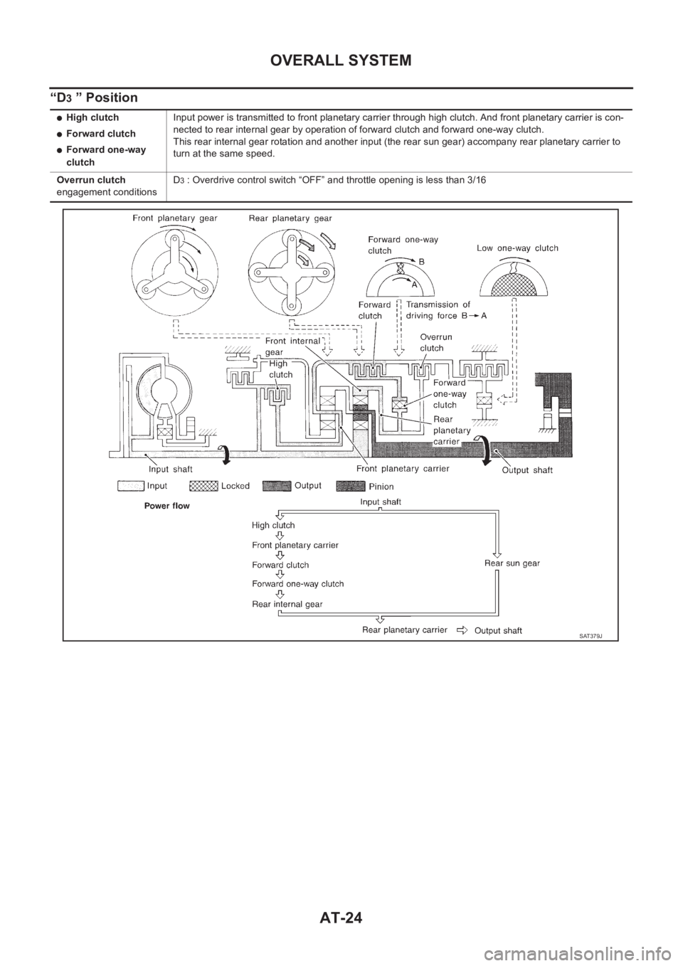
“D3 ” Position
●High clutch
●Forward clutch
●Forward one-way
clutchInput power is transmitted to front planetary carrier through high clutch. And front planetary carrier is con-
nected to rear internal gear by operation of forward clutch and forward one-way clutch.
This rear internal gear rotation and another input (the rear sun gear) accompany rear planetary carrier to
turn at the same speed.
Overrun clutch
engagement conditionsD
3 : Overdrive control switch “OFF” and throttle opening is less than 3/16
SAT379J
Page 1483 of 3189
OVERALL SYSTEM
AT-27
D
E
F
G
H
I
J
K
L
MA
B
AT
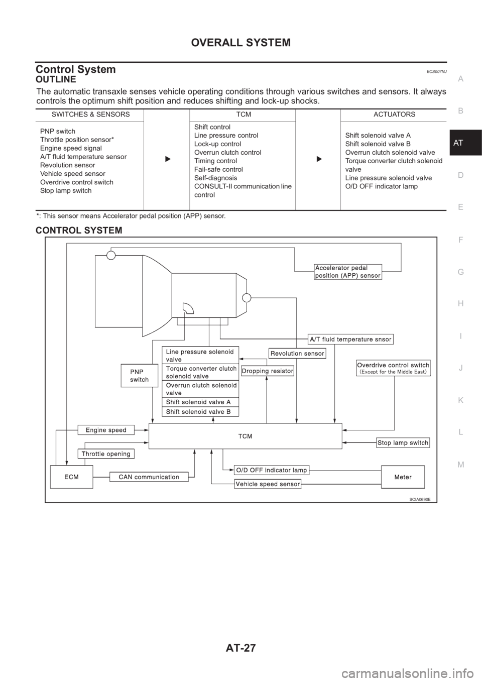
Control SystemECS007NJ
OUTLINE
The automatic transaxle senses vehicle operating conditions through various switches and sensors. It always
controls the optimum shift position and reduces shifting and lock-up shocks.
*: This sensor means Accelerator pedal position (APP) sensor.
CONTROL SYSTEM
SWITCHES & SENSORS TCM ACTUATORS
PNP switch
Throttle position sensor*
Engine speed signal
A/T fluid temperature sensor
Revolution sensor
Vehicle speed sensor
Overdrive control switch
Stop lamp switchShift control
Line pressure control
Lock-up control
Overrun clutch control
Timing control
Fail-safe control
Self-diagnosis
CONSULT-II communication line
controlShift solenoid valve A
Shift solenoid valve B
Overrun clutch solenoid valve
Torque converter clutch solenoid
valve
Line pressure solenoid valve
O/D OFF indicator lamp
SCIA0690E
Page 1484 of 3189
AT-28
OVERALL SYSTEM
TCM FUNCTION
The function of the TCM is to:
●Receive input signals sent from various switches and sensors.
●Determine required line pressure, shifting point, lock-up operation, and engine brake operation.
●Send required output signals to the respective solenoid valves.
INPUT/OUTPUT SIGNAL OF TCM
Control MechanismECS007NK
LINE PRESSURE CONTROL
TCM has various line pressure control characteristics to match the driving conditions.
An ON-OFF duty signal is sent to the line pressure solenoid valve based on TCM characteristics.
Hydraulic pressure on the clutch and brake is electronically controlled through the line pressure solenoid valve
to accommodate engine torque. This results in smooth shift operation.
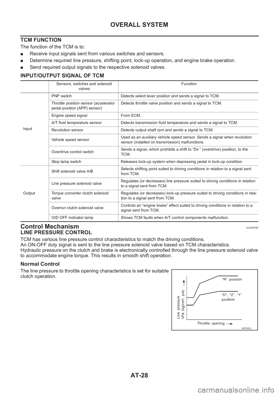
Normal Control
The line pressure to throttle opening characteristics is set for suitable
clutch operation.
Sensors, switches and solenoid
valvesFunction
InputPNP switch Detects select lever position and sends a signal to TCM.
Throttle position sensor (accelerator
pedal position (APP) sensor)Detects throttle valve position and sends a signal to TCM.
Engine speed signal From ECM.
A/T fluid temperature sensor Detects transmission fluid temperature and sends a signal to TCM.
Revolution sensor Detects output shaft rpm and sends a signal to TCM.
Vehicle speed sensorUsed as an auxiliary vehicle speed sensor. Sends a signal when revolution
sensor (installed on transmission) malfunctions.
Overdrive control switchSends a signal, which prohibits a shift to “D
4 ” (overdrive) position, to the
TCM.
Stop lamp switch Releases lock-up system when depressing pedal in lock-up condition.
OutputShift solenoid valve A/BSelects shifting point suited to driving conditions in relation to a signal sent
from TCM.
Line pressure solenoid valveRegulates (or decreases) line pressure suited to driving conditions in relation
to a signal sent from TCM.
Torque converter clutch solenoid
valveRegulates (or decreases) lock-up pressure suited to driving conditions in rela-
tion to a signal sent from TCM.
Overrun clutch solenoid valveControls an “engine brake” effect suited to driving conditions in relation to a
signal sent from TCM.
O/D OFF indicator lamp Shows TCM faults when A/T control components malfunction.
SAT003J