NISSAN ALMERA TINO 2001 Service Repair Manual
ALMERA TINO 2001
NISSAN
NISSAN
https://www.carmanualsonline.info/img/5/57352/w960_57352-0.png
NISSAN ALMERA TINO 2001 Service Repair Manual
Trending: rims, hood open, steering wheel adjustment, key battery, turn signal bulb, oil change, BT-32
Page 1581 of 3051
![NISSAN ALMERA TINO 2001 Service Repair Manual TERMI-
NAL
NO.WIRE
COLORITEM CONDITION DATA(DC Voltage)
434 W Accelerator position sensor[Ignition switch ªONº]
+Accelerator pedal fully released0.30 - 0.50V
[Ignition switch ªONº]
+Accelerator pe NISSAN ALMERA TINO 2001 Service Repair Manual TERMI-
NAL
NO.WIRE
COLORITEM CONDITION DATA(DC Voltage)
434 W Accelerator position sensor[Ignition switch ªONº]
+Accelerator pedal fully released0.30 - 0.50V
[Ignition switch ªONº]
+Accelerator pe](/img/5/57352/w960_57352-1580.png)
TERMI-
NAL
NO.WIRE
COLORITEM CONDITION DATA(DC Voltage)
434 W Accelerator position sensor[Ignition switch ªONº]
+Accelerator pedal fully released0.30 - 0.50V
[Ignition switch ªONº]
+Accelerator pedal fully depressed3.0 - 4.3V
435 W/GAccelerator position switch
(Idle)[Ignition switch ªONº]
+Accelerator pedal fully releasedApproximately 0V
[Ignition switch ªONº]
+Accelerator pedal depressedBATTERY VOLTAGE
(11 - 14V)
On Board Diagnosis LogicNLEC0682
DTC Malfunction is detected when ... Check Items (Possible Cause)
P0120
0403+The relation between sensor and switch signals
is not in the nomal range during the specified
accelerator positions.+Harness or connectors
(The sensor circuit is open or shorted.)
+Accelerator position sensor
+Accelerator position switch
SEF817Y
DTC Confirmation ProcedureNLEC0683WITH CONSULT-IINLEC0683S011) Turn ignition switch ªONº.
2) Select ªDATA MONITORº mode with CONSULT-II.
3) Depress and release fully accelerator pedal slowly.
4) If DTC is detected, go to ªDiagnostic Procedureº, EC-1159.
WITHOUT CONSULT-IINLEC0683S021) Turn ignition switch ªONº.
2) Depress and release fully accelerator pedal slowly.
3) Turn ignition switch ªOFFº, wait at least 5 seconds and then
turn ªONº.
4) Perform ªDiagnostic Test Mode II (Self-diagnostic results)º with
ECM.
5) If DTC is detected, go to ªDiagnostic Procedureº, EC-1159.
DTC P0120 ACCEL POS SENSORYD22DDTI
ECM Terminals and Reference Value (Cont'd)
EC-1156
Page 1582 of 3051
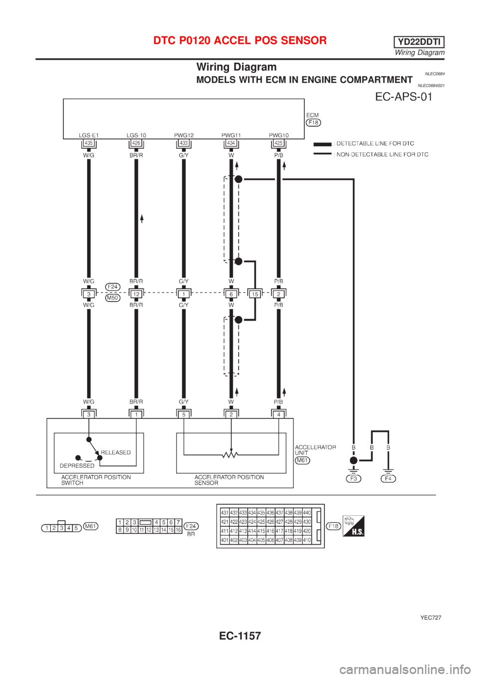
Wiring DiagramNLEC0684MODELS WITH ECM IN ENGINE COMPARTMENTNLEC0684S01
YEC727
DTC P0120 ACCEL POS SENSORYD22DDTI
Wiring Diagram
EC-1157
Page 1583 of 3051
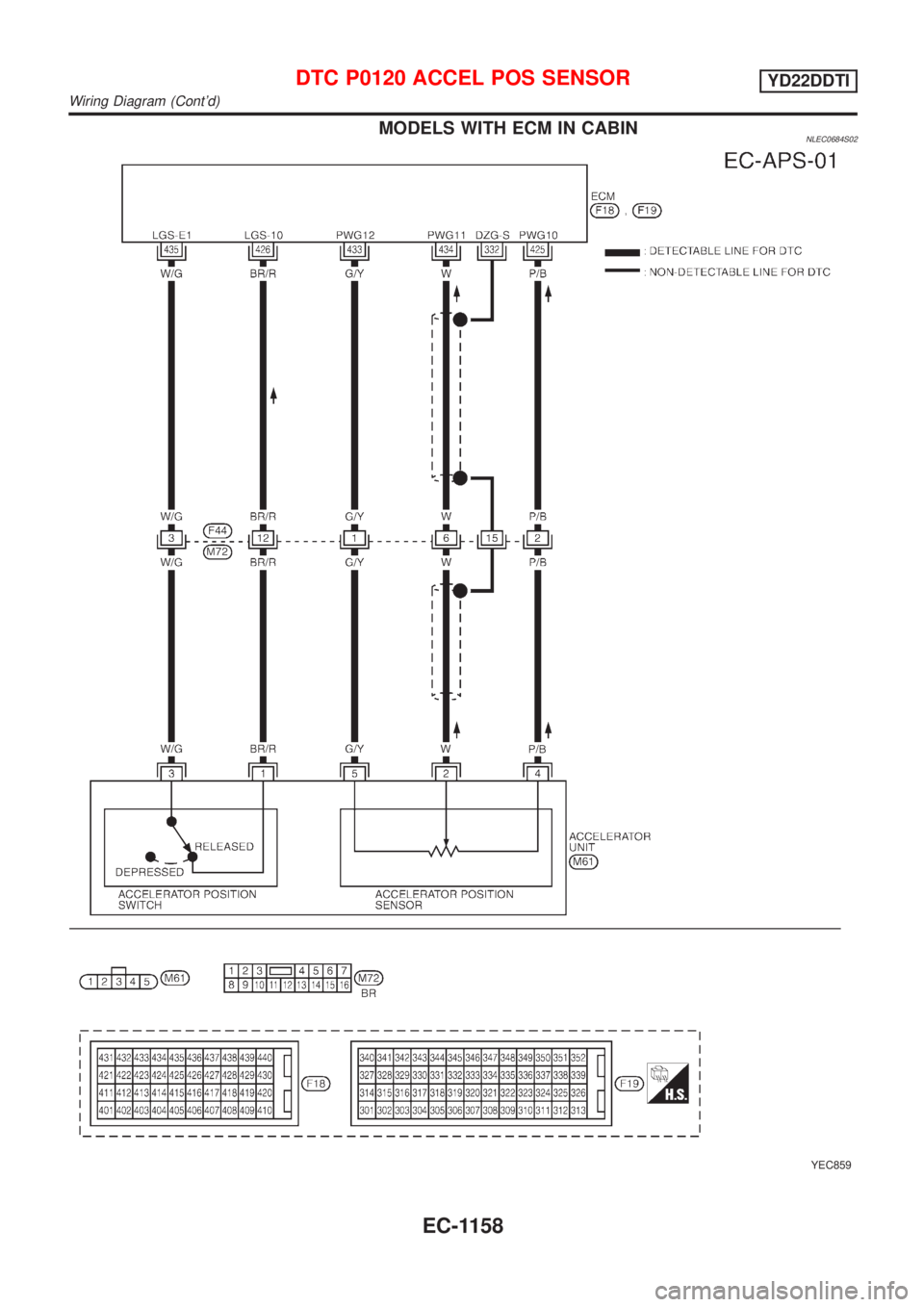
MODELS WITH ECM IN CABINNLEC0684S02
YEC859
DTC P0120 ACCEL POS SENSORYD22DDTI
Wiring Diagram (Cont'd)
EC-1158
Page 1584 of 3051
Diagnostic ProcedureNLEC0685
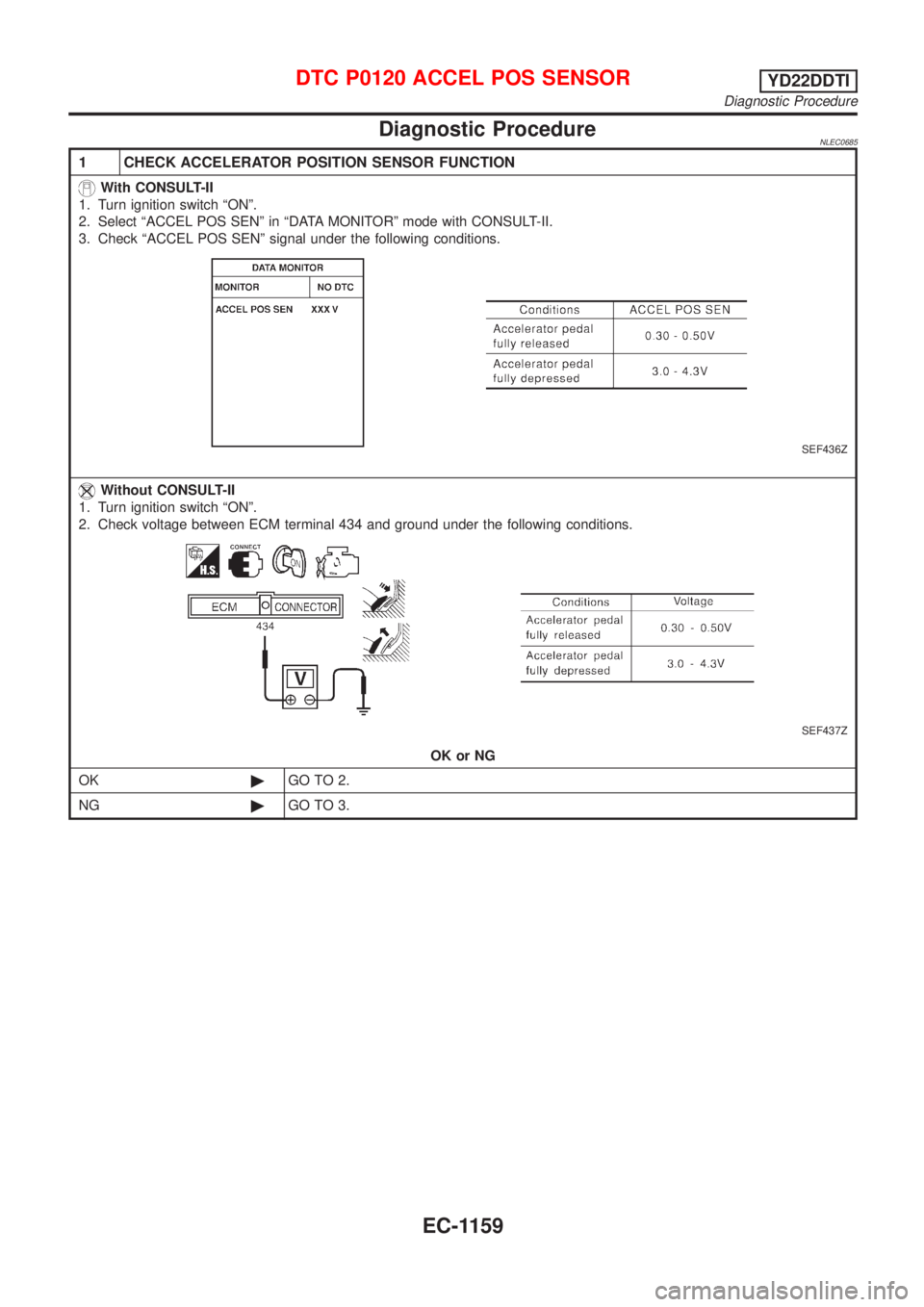
1 CHECK ACCELERATOR POSITION SENSOR FUNCTION
With CONSULT-II
1. Turn ignition switch ªONº.
2. Select ªACCEL POS SENº in ªDATA MONITORº mode with CONSULT-II.
3. Check ªACCEL POS SENº signal under the following conditions.
SEF436Z
Without CONSULT-II
1. Turn ignition switch ªONº.
2. Check voltage between ECM terminal 434 and ground under the following conditions.
SEF437Z
OK or NG
OK©GO TO 2.
NG©GO TO 3.
DTC P0120 ACCEL POS SENSORYD22DDTI
Diagnostic Procedure
EC-1159
Page 1585 of 3051
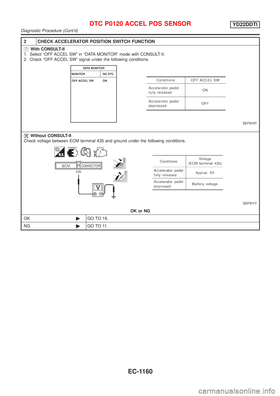
2 CHECK ACCELERATOR POSITION SWITCH FUNCTION
With CONSULT-II
1. Select ªOFF ACCEL SWº in ªDATA MONITORº mode with CONSULT-II.
2. Check ªOFF ACCEL SWº signal under the following conditions.
SEF910Y
Without CONSULT-II
Check voltage between ECM terminal 435 and ground under the following conditions.
SEF911Y
OK or NG
OK©GO TO 16.
NG©GO TO 11.
DTC P0120 ACCEL POS SENSORYD22DDTI
Diagnostic Procedure (Cont'd)
EC-1160
Page 1586 of 3051
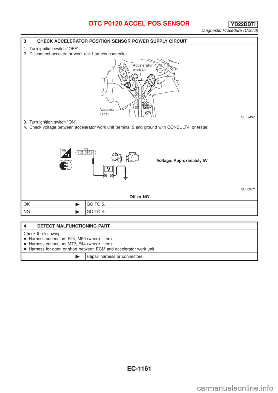
3 CHECK ACCELERATOR POSITION SENSOR POWER SUPPLY CIRCUIT
1. Turn ignition switch ªOFFº.
2. Disconnect accelerator work unit harness connector.
SEF749Z
3. Turn ignition switch ªONº.
4. Check voltage between accelerator work unit terminal 5 and ground with CONSULT-II or tester.
SEF897Y
OK or NG
OK©GO TO 5.
NG©GO TO 4.
4 DETECT MALFUNCTIONING PART
Check the following.
+Harness connectors F24, M50 (where fitted)
+Harness connectors M72, F44 (where fitted)
+Harness for open or short between ECM and accelerator work unit
©Repair harness or connectors.
DTC P0120 ACCEL POS SENSORYD22DDTI
Diagnostic Procedure (Cont'd)
EC-1161
Page 1587 of 3051
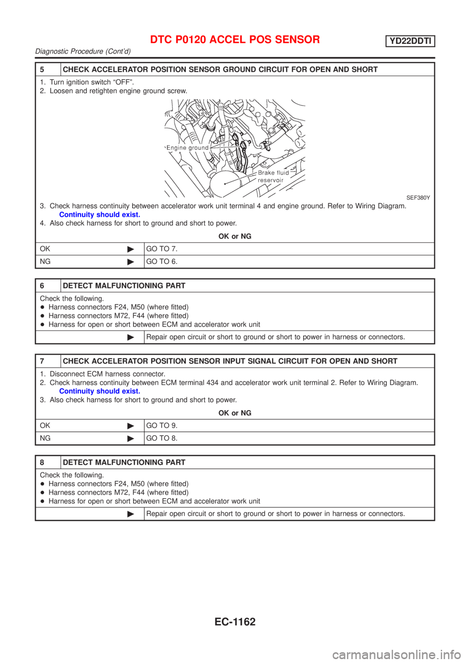
5 CHECK ACCELERATOR POSITION SENSOR GROUND CIRCUIT FOR OPEN AND SHORT
1. Turn ignition switch ªOFFº.
2. Loosen and retighten engine ground screw.
SEF380Y
3. Check harness continuity between accelerator work unit terminal 4 and engine ground. Refer to Wiring Diagram.
Continuity should exist.
4. Also check harness for short to ground and short to power.
OK or NG
OK©GO TO 7.
NG©GO TO 6.
6 DETECT MALFUNCTIONING PART
Check the following.
+Harness connectors F24, M50 (where fitted)
+Harness connectors M72, F44 (where fitted)
+Harness for open or short between ECM and accelerator work unit
©Repair open circuit or short to ground or short to power in harness or connectors.
7 CHECK ACCELERATOR POSITION SENSOR INPUT SIGNAL CIRCUIT FOR OPEN AND SHORT
1. Disconnect ECM harness connector.
2. Check harness continuity between ECM terminal 434 and accelerator work unit terminal 2. Refer to Wiring Diagram.
Continuity should exist.
3. Also check harness for short to ground and short to power.
OK or NG
OK©GO TO 9.
NG©GO TO 8.
8 DETECT MALFUNCTIONING PART
Check the following.
+Harness connectors F24, M50 (where fitted)
+Harness connectors M72, F44 (where fitted)
+Harness for open or short between ECM and accelerator work unit
©Repair open circuit or short to ground or short to power in harness or connectors.
DTC P0120 ACCEL POS SENSORYD22DDTI
Diagnostic Procedure (Cont'd)
EC-1162
Page 1588 of 3051
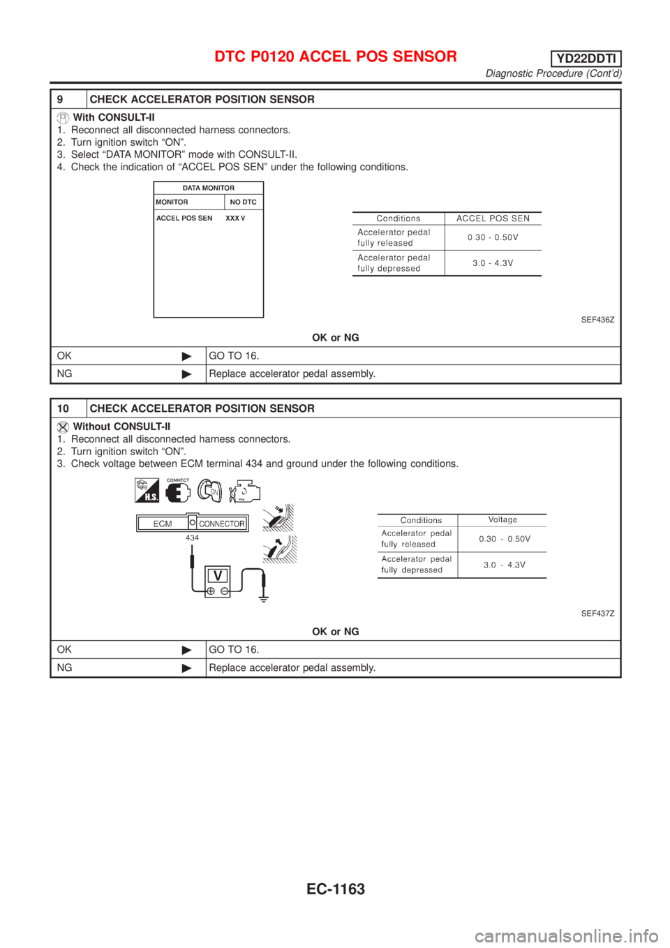
9 CHECK ACCELERATOR POSITION SENSOR
With CONSULT-II
1. Reconnect all disconnected harness connectors.
2. Turn ignition switch ªONº.
3. Select ªDATA MONITORº mode with CONSULT-II.
4. Check the indication of ªACCEL POS SENº under the following conditions.
SEF436Z
OK or NG
OK©GO TO 16.
NG©Replace accelerator pedal assembly.
10 CHECK ACCELERATOR POSITION SENSOR
Without CONSULT-II
1. Reconnect all disconnected harness connectors.
2. Turn ignition switch ªONº.
3. Check voltage between ECM terminal 434 and ground under the following conditions.
SEF437Z
OK or NG
OK©GO TO 16.
NG©Replace accelerator pedal assembly.
DTC P0120 ACCEL POS SENSORYD22DDTI
Diagnostic Procedure (Cont'd)
EC-1163
Page 1589 of 3051
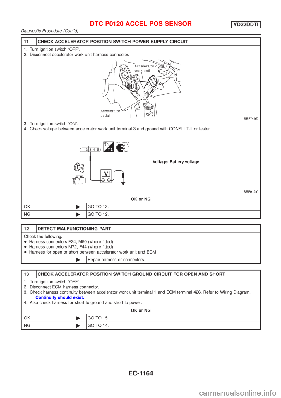
11 CHECK ACCELERATOR POSITION SWITCH POWER SUPPLY CIRCUIT
1. Turn ignition switch ªOFFº.
2. Disconnect accelerator work unit harness connector.
SEF749Z
3. Turn ignition switch ªONº.
4. Check voltage between accelerator work unit terminal 3 and ground with CONSULT-II or tester.
SEF912Y
OK or NG
OK©GO TO 13.
NG©GO TO 12.
12 DETECT MALFUNCTIONING PART
Check the following.
+Harness connectors F24, M50 (where fitted)
+Harness connectors M72, F44 (where fitted)
+Harness for open or short between accelerator work unit and ECM
©Repair harness or connectors.
13 CHECK ACCELERATOR POSITION SWITCH GROUND CIRCUIT FOR OPEN AND SHORT
1. Turn ignition switch ªOFFº.
2. Disconnect ECM harness connector.
3. Check harness continuity between accelerator work unit terminal 1 and ECM terminal 426. Refer to Wiring Diagram.
Continuity should exist.
4. Also check harness for short to ground and short to power.
OK or NG
OK©GO TO 15.
NG©GO TO 14.
DTC P0120 ACCEL POS SENSORYD22DDTI
Diagnostic Procedure (Cont'd)
EC-1164
Page 1590 of 3051
14 DETECT MALFUNCTIONING PART
Check the following.
+Harness connectors F24, M50 (where fitted)
+Harness connectors M72, F44 (where fitted)
+Harness for open or short between ECM and accelerator work unit
©Repair open circuit or short to ground or short to power in harness or connectors.
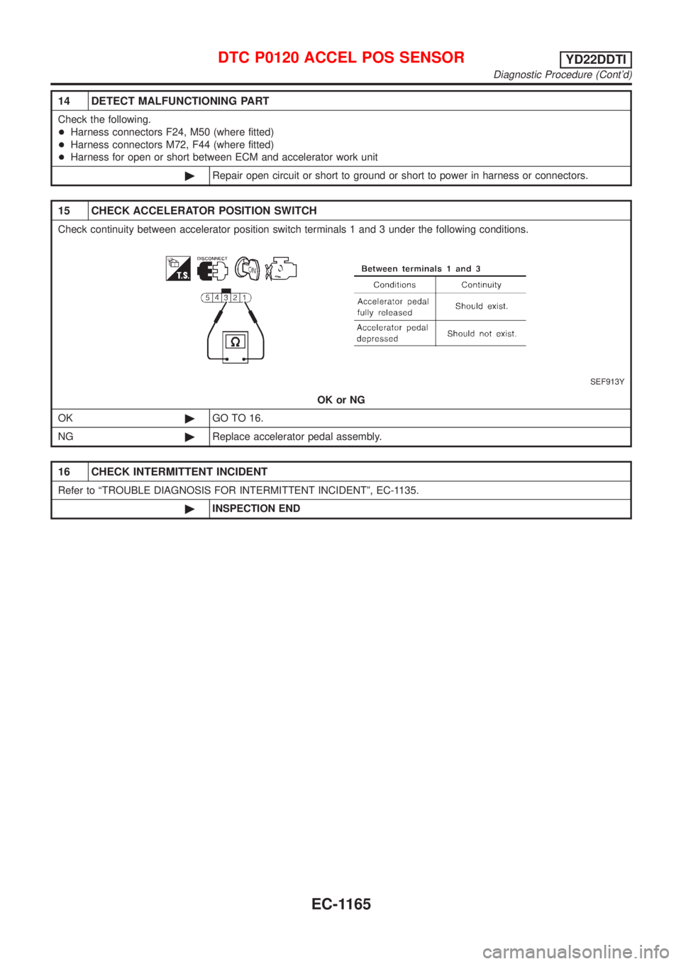
15 CHECK ACCELERATOR POSITION SWITCH
Check continuity between accelerator position switch terminals 1 and 3 under the following conditions.
SEF913Y
OK or NG
OK©GO TO 16.
NG©Replace accelerator pedal assembly.
16 CHECK INTERMITTENT INCIDENT
Refer to ªTROUBLE DIAGNOSIS FOR INTERMITTENT INCIDENTº, EC-1135.
©INSPECTION END
DTC P0120 ACCEL POS SENSORYD22DDTI
Diagnostic Procedure (Cont'd)
EC-1165
Trending: oil pressure, fuel consumption, Trim, clock reset, oil type, wiper relay place, dead battery
![NISSAN ALMERA TINO 2001 Service Repair Manual TERMI-
NAL
NO.WIRE
COLORITEM CONDITION DATA(DC Voltage)
434 W Accelerator position sensor[Ignition switch ªONº]
+Accelerator pedal fully released0.30 - 0.50V
[Ignition switch ªONº]
+Accelerator pe NISSAN ALMERA TINO 2001 Service Repair Manual TERMI-
NAL
NO.WIRE
COLORITEM CONDITION DATA(DC Voltage)
434 W Accelerator position sensor[Ignition switch ªONº]
+Accelerator pedal fully released0.30 - 0.50V
[Ignition switch ªONº]
+Accelerator pe](/img/5/57352/w960_57352-1580.png)
