NISSAN ALMERA TINO 2001 Service Repair Manual
ALMERA TINO 2001
NISSAN
NISSAN
https://www.carmanualsonline.info/img/5/57352/w960_57352-0.png
NISSAN ALMERA TINO 2001 Service Repair Manual
Trending: spare tire, change language, airbag, maintenance schedule, remove seats, brake sensor, run flat
Page 1591 of 3051
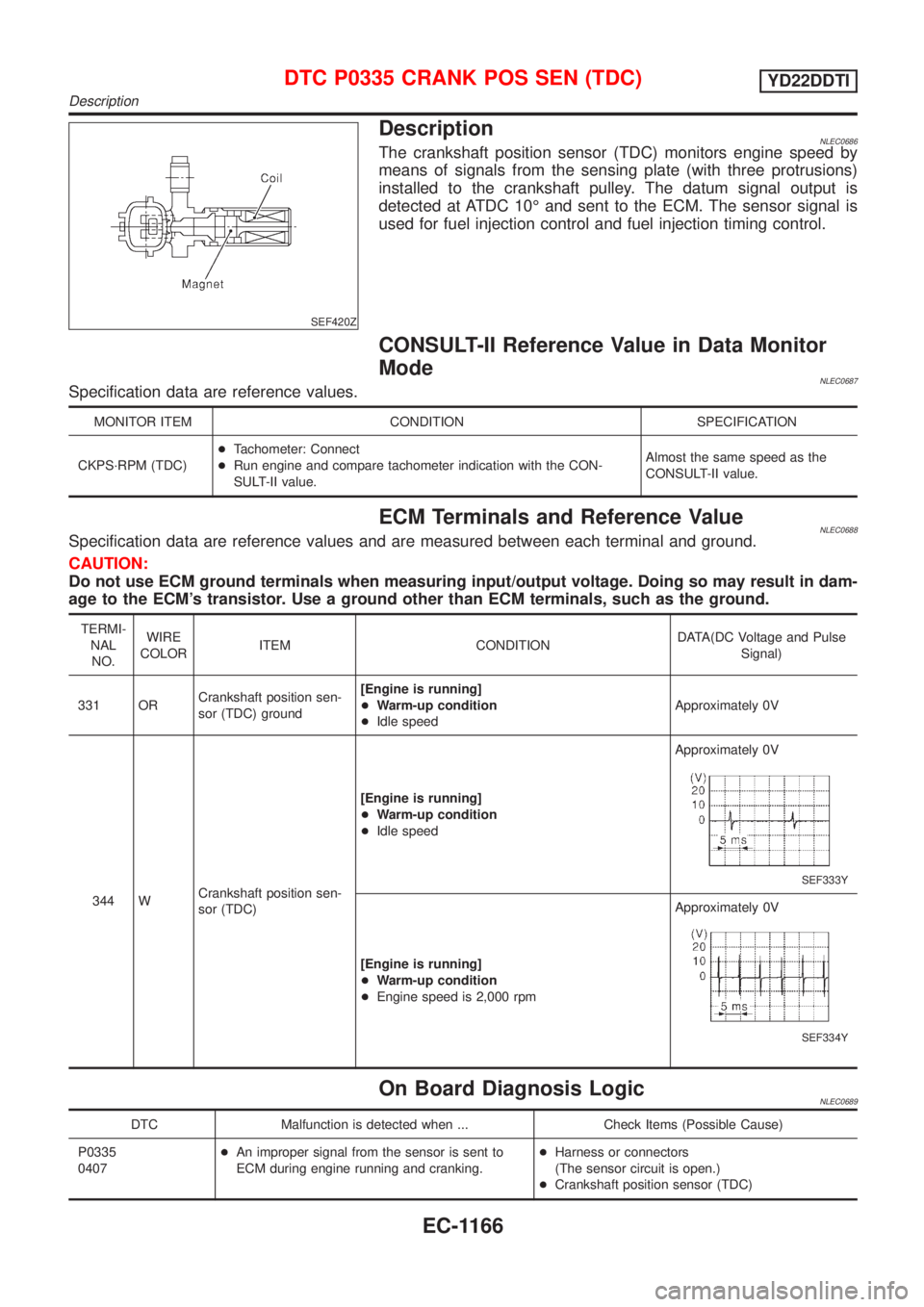
SEF420Z
DescriptionNLEC0686The crankshaft position sensor (TDC) monitors engine speed by
means of signals from the sensing plate (with three protrusions)
installed to the crankshaft pulley. The datum signal output is
detected at ATDC 10É and sent to the ECM. The sensor signal is
used for fuel injection control and fuel injection timing control.
CONSULT-II Reference Value in Data Monitor
Mode
NLEC0687Specification data are reference values.
MONITOR ITEM CONDITION SPECIFICATION
CKPS´RPM (TDC)+Tachometer: Connect
+Run engine and compare tachometer indication with the CON-
SULT-II value.Almost the same speed as the
CONSULT-II value.
ECM Terminals and Reference ValueNLEC0688Specification data are reference values and are measured between each terminal and ground.
CAUTION:
Do not use ECM ground terminals when measuring input/output voltage. Doing so may result in dam-
age to the ECM's transistor. Use a ground other than ECM terminals, such as the ground.
TERMI-
NAL
NO.WIRE
COLORITEM CONDITIONDATA(DC Voltage and Pulse
Signal)
331 ORCrankshaft position sen-
sor (TDC) ground[Engine is running]
+Warm-up condition
+Idle speedApproximately 0V
344 WCrankshaft position sen-
sor (TDC)[Engine is running]
+Warm-up condition
+Idle speedApproximately 0V
SEF333Y
[Engine is running]
+Warm-up condition
+Engine speed is 2,000 rpmApproximately 0V
SEF334Y
On Board Diagnosis LogicNLEC0689
DTC Malfunction is detected when ... Check Items (Possible Cause)
P0335
0407+An improper signal from the sensor is sent to
ECM during engine running and cranking.+Harness or connectors
(The sensor circuit is open.)
+Crankshaft position sensor (TDC)
DTC P0335 CRANK POS SEN (TDC)YD22DDTI
Description
EC-1166
Page 1592 of 3051
SEF817Y
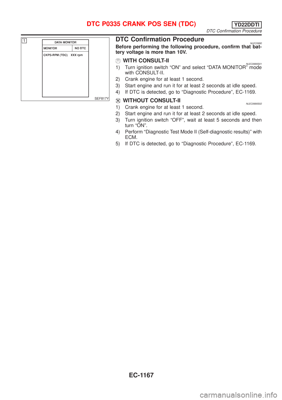
DTC Confirmation ProcedureNLEC0690Before performing the following procedure, confirm that bat-
tery voltage is more than 10V.
WITH CONSULT-IINLEC0690S011) Turn ignition switch ªONº and select ªDATA MONITORº mode
with CONSULT-II.
2) Crank engine for at least 1 second.
3) Start engine and run it for at least 2 seconds at idle speed.
4) If DTC is detected, go to ªDiagnostic Procedureº, EC-1169.
WITHOUT CONSULT-IINLEC0690S021) Crank engine for at least 1 second.
2) Start engine and run it for at least 2 seconds at idle speed.
3) Turn ignition switch ªOFFº, wait at least 5 seconds and then
turn ªONº.
4) Perform ªDiagnostic Test Mode II (Self-diagnostic results)º with
ECM.
5) If DTC is detected, go to ªDiagnostic Procedureº, EC-1169.
DTC P0335 CRANK POS SEN (TDC)YD22DDTI
DTC Confirmation Procedure
EC-1167
Page 1593 of 3051
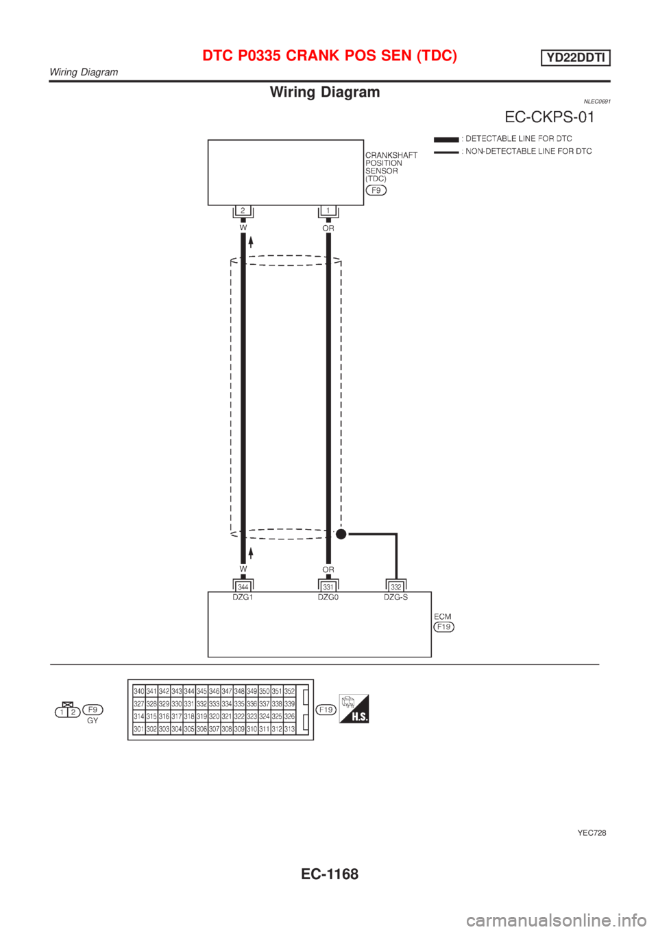
Wiring DiagramNLEC0691
YEC728
DTC P0335 CRANK POS SEN (TDC)YD22DDTI
Wiring Diagram
EC-1168
Page 1594 of 3051
Diagnostic ProcedureNLEC0692
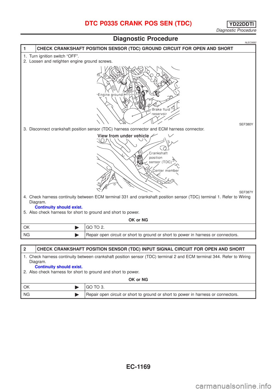
1 CHECK CRANKSHAFT POSITION SENSOR (TDC) GROUND CIRCUIT FOR OPEN AND SHORT
1. Turn ignition switch ªOFFº.
2. Loosen and retighten engine ground screws.
SEF380Y
3. Disconnect crankshaft position sensor (TDC) harness connector and ECM harness connector.
SEF387Y
4. Check harness continuity between ECM terminal 331 and crankshaft position sensor (TDC) terminal 1. Refer to Wiring
Diagram.
Continuity should exist.
5. Also check harness for short to ground and short to power.
OK or NG
OK©GO TO 2.
NG©Repair open circuit or short to ground or short to power in harness or connectors.
2 CHECK CRANKSHAFT POSITION SENSOR (TDC) INPUT SIGNAL CIRCUIT FOR OPEN AND SHORT
1. Check harness continuity between crankshaft position sensor (TDC) terminal 2 and ECM terminal 344. Refer to Wiring
Diagram.
Continuity should exist.
2. Also check harness for short to ground and short to power.
OK or NG
OK©GO TO 3.
NG©Repair open circuit or short to ground or short to power in harness or connectors.
DTC P0335 CRANK POS SEN (TDC)YD22DDTI
Diagnostic Procedure
EC-1169
Page 1595 of 3051
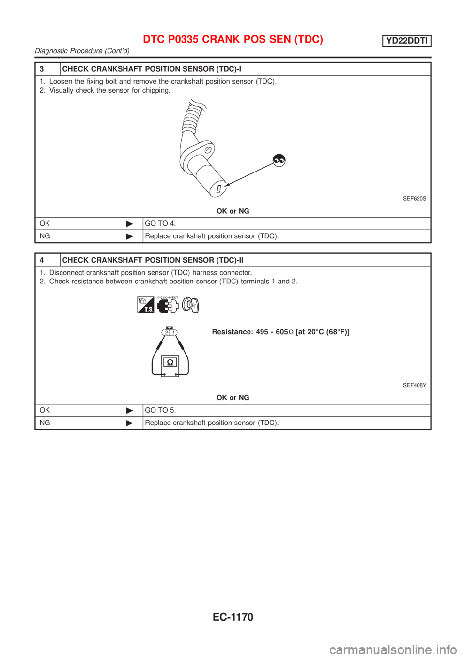
3 CHECK CRANKSHAFT POSITION SENSOR (TDC)-I
1. Loosen the fixing bolt and remove the crankshaft position sensor (TDC).
2. Visually check the sensor for chipping.
SEF620S
OK or NG
OK©GO TO 4.
NG©Replace crankshaft position sensor (TDC).
4 CHECK CRANKSHAFT POSITION SENSOR (TDC)-II
1. Disconnect crankshaft position sensor (TDC) harness connector.
2. Check resistance between crankshaft position sensor (TDC) terminals 1 and 2.
SEF408Y
OK or NG
OK©GO TO 5.
NG©Replace crankshaft position sensor (TDC).
DTC P0335 CRANK POS SEN (TDC)YD22DDTI
Diagnostic Procedure (Cont'd)
EC-1170
Page 1596 of 3051
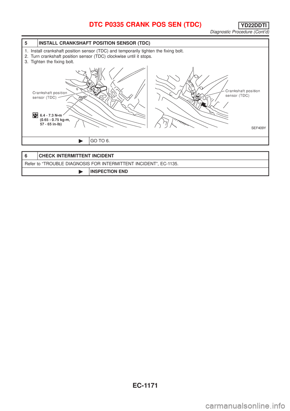
5 INSTALL CRANKSHAFT POSITION SENSOR (TDC)
1. Install crankshaft position sensor (TDC) and temporarily tighten the fixing bolt.
2. Turn crankshaft position sensor (TDC) clockwise until it stops.
3. Tighten the fixing bolt.
SEF409Y
©GO TO 6.
6 CHECK INTERMITTENT INCIDENT
Refer to ªTROUBLE DIAGNOSIS FOR INTERMITTENT INCIDENTº, EC-1135.
©INSPECTION END
DTC P0335 CRANK POS SEN (TDC)YD22DDTI
Diagnostic Procedure (Cont'd)
EC-1171
Page 1597 of 3051
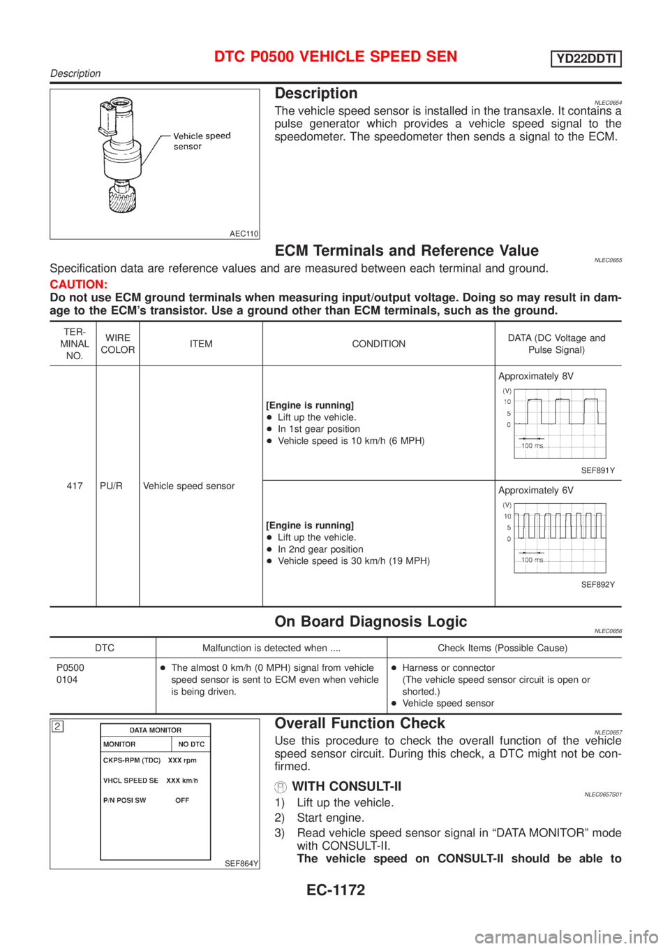
AEC110
DescriptionNLEC0654The vehicle speed sensor is installed in the transaxle. It contains a
pulse generator which provides a vehicle speed signal to the
speedometer. The speedometer then sends a signal to the ECM.
ECM Terminals and Reference ValueNLEC0655Specification data are reference values and are measured between each terminal and ground.
CAUTION:
Do not use ECM ground terminals when measuring input/output voltage. Doing so may result in dam-
age to the ECM's transistor. Use a ground other than ECM terminals, such as the ground.
TER-
MINAL
NO.WIRE
COLORITEM CONDITIONDATA (DC Voltage and
Pulse Signal)
417 PU/R Vehicle speed sensor[Engine is running]
+Lift up the vehicle.
+In 1st gear position
+Vehicle speed is 10 km/h (6 MPH)Approximately 8V
SEF891Y
[Engine is running]
+Lift up the vehicle.
+In 2nd gear position
+Vehicle speed is 30 km/h (19 MPH)Approximately 6V
SEF892Y
On Board Diagnosis LogicNLEC0656
DTC Malfunction is detected when .... Check Items (Possible Cause)
P0500
0104+The almost 0 km/h (0 MPH) signal from vehicle
speed sensor is sent to ECM even when vehicle
is being driven.+Harness or connector
(The vehicle speed sensor circuit is open or
shorted.)
+Vehicle speed sensor
SEF864Y
Overall Function CheckNLEC0657Use this procedure to check the overall function of the vehicle
speed sensor circuit. During this check, a DTC might not be con-
firmed.
WITH CONSULT-IINLEC0657S011) Lift up the vehicle.
2) Start engine.
3) Read vehicle speed sensor signal in ªDATA MONITORº mode
with CONSULT-II.
The vehicle speed on CONSULT-II should be able to
DTC P0500 VEHICLE SPEED SENYD22DDTI
Description
EC-1172
Page 1598 of 3051
exceed 10 km/h (6 MPH) when rotating wheels with suit-
able gear position.
4) If NG, go to ªDiagnostic Procedureº, EC-1176.
WITHOUT CONSULT-IINLEC0657S021) Lift up the vehicle.
2) Start engine.
3) Read the voltage signal for the vehicle speed sensor with an
oscilloscope. Refer to ªECM Terminals and Reference Valueº,
EC-1172.
4) Verify that the oscilloscope screen shows the signal wave as
shown at ªECM Terminals and Reference Valueº, EC-1172.
5) If NG, go to ªDiagnostic Procedureº, EC-1176.
DTC P0500 VEHICLE SPEED SENYD22DDTI
Overall Function Check (Cont'd)
EC-1173
Page 1599 of 3051
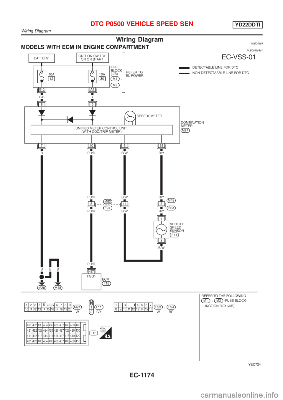
Wiring DiagramNLEC0658MODELS WITH ECM IN ENGINE COMPARTMENTNLEC0658S01
YEC724
DTC P0500 VEHICLE SPEED SENYD22DDTI
Wiring Diagram
EC-1174
Page 1600 of 3051
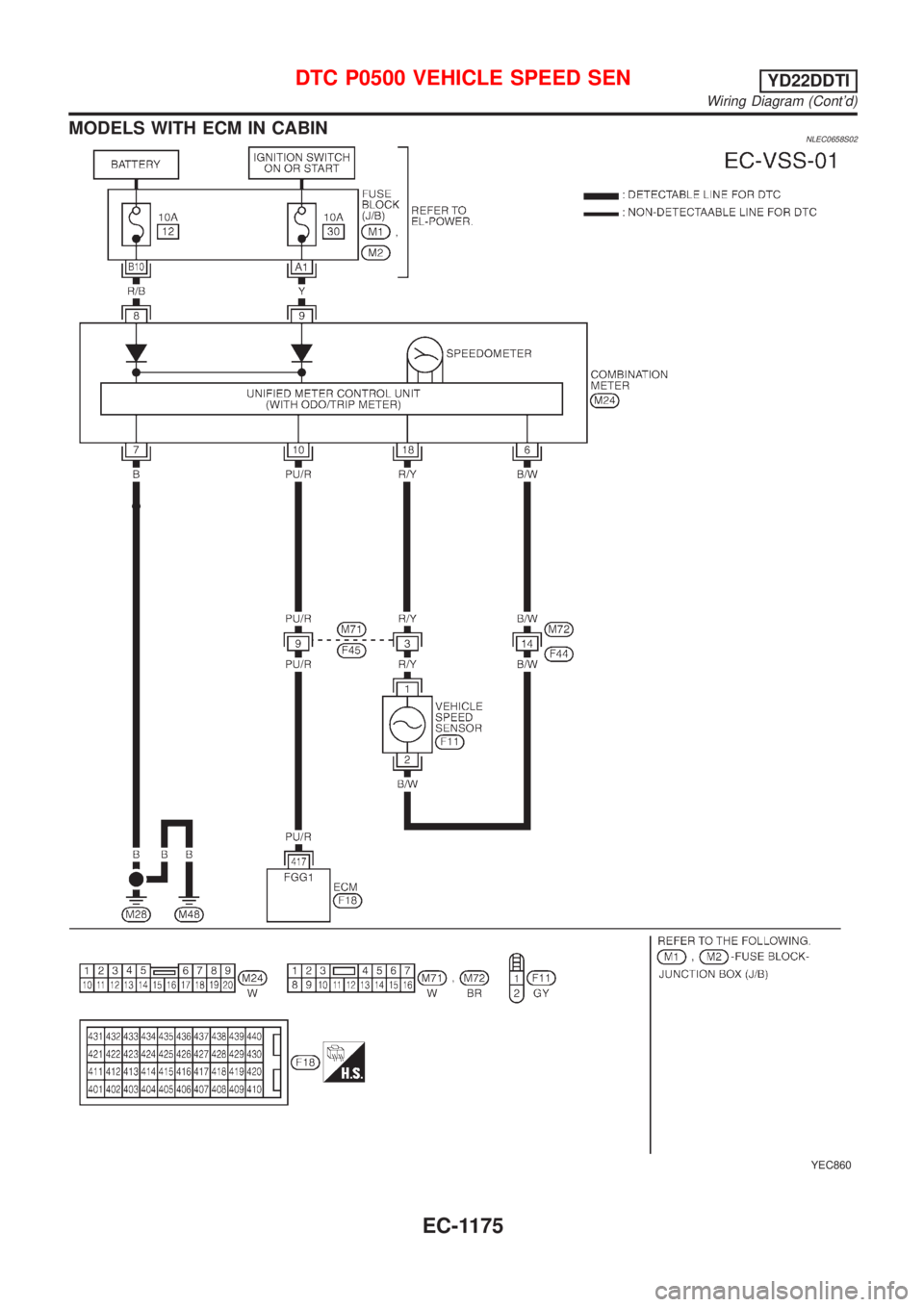
MODELS WITH ECM IN CABINNLEC0658S02
YEC860
DTC P0500 VEHICLE SPEED SENYD22DDTI
Wiring Diagram (Cont'd)
EC-1175
Trending: low beam, wheel bolt torque, automatic transmission fluid, maintenance schedule, radiator, octane, battery replacement

