NISSAN ALMERA TINO 2001 Service Repair Manual
Manufacturer: NISSAN, Model Year: 2001, Model line: ALMERA TINO, Model: NISSAN ALMERA TINO 2001Pages: 3051, PDF Size: 46.38 MB
Page 1871 of 3051
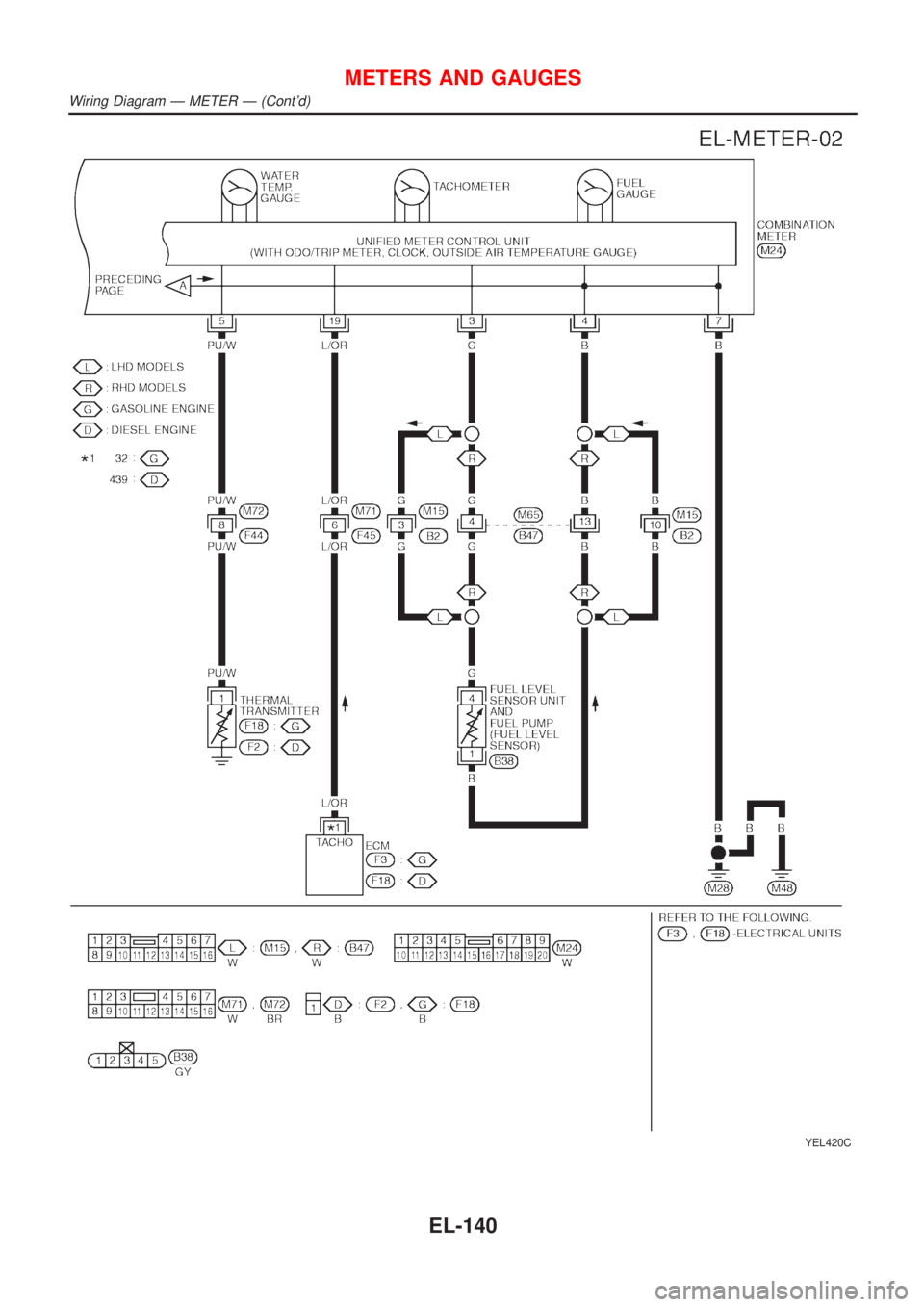
YEL420C
METERS AND GAUGES
Wiring Diagram Ð METER Ð (Cont'd)
EL-140
Page 1872 of 3051
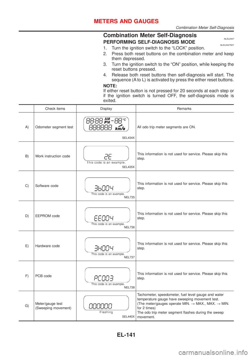
Combination Meter Self-DiagnosisNLEL0447PERFORMING SELF-DIAGNOSIS MODENLEL0447S011. Turn the ignition switch to the ªLOCKº position.
2. Press both reset buttons on the combination meter and keep
them depressed.
3. Turn the ignition switch to the ªONº position, while keeping the
reset buttons pressed.
4. Release both reset buttons then self-diagnosis will start. The
sequence (A to L) is activated by press the either reset buttons.
NOTE:
If either reset button is not pressed for 20 seconds at each step or
if the ignition switch is turned OFF, the self-diagnosis mode is
exited.
Check items Display Remarks
A) Odometer segment test
SEL434X
All odo trip meter segments are ON.
B) Work instruction code
SEL435X
This information is not used for service. Please skip this
step.
C) Software code
NEL735
This information is not used for service. Please skip this
step.
D) EEPROM code
NEL736
This information is not used for service. Please skip this
step.
E) Hardware code
NEL737
This information is not used for service. Please skip this
step.
F) PCB code
NEL738
This information is not used for service. Please skip this
step.
G)Meter/gauge test
(Sweeping movement)
SEL440X
Tachometer, speedometer, fuel level gauge and water
temperature gauge have sweeping movement test.
(The meter/gauges operate MIN.®MAX., MAX.®MIN.
for 2 times)
The odo trip meter segment flashes during the sweep
movement.
METERS AND GAUGES
Combination Meter Self-Diagnosis
EL-141
Page 1873 of 3051
Check items Display Remarks
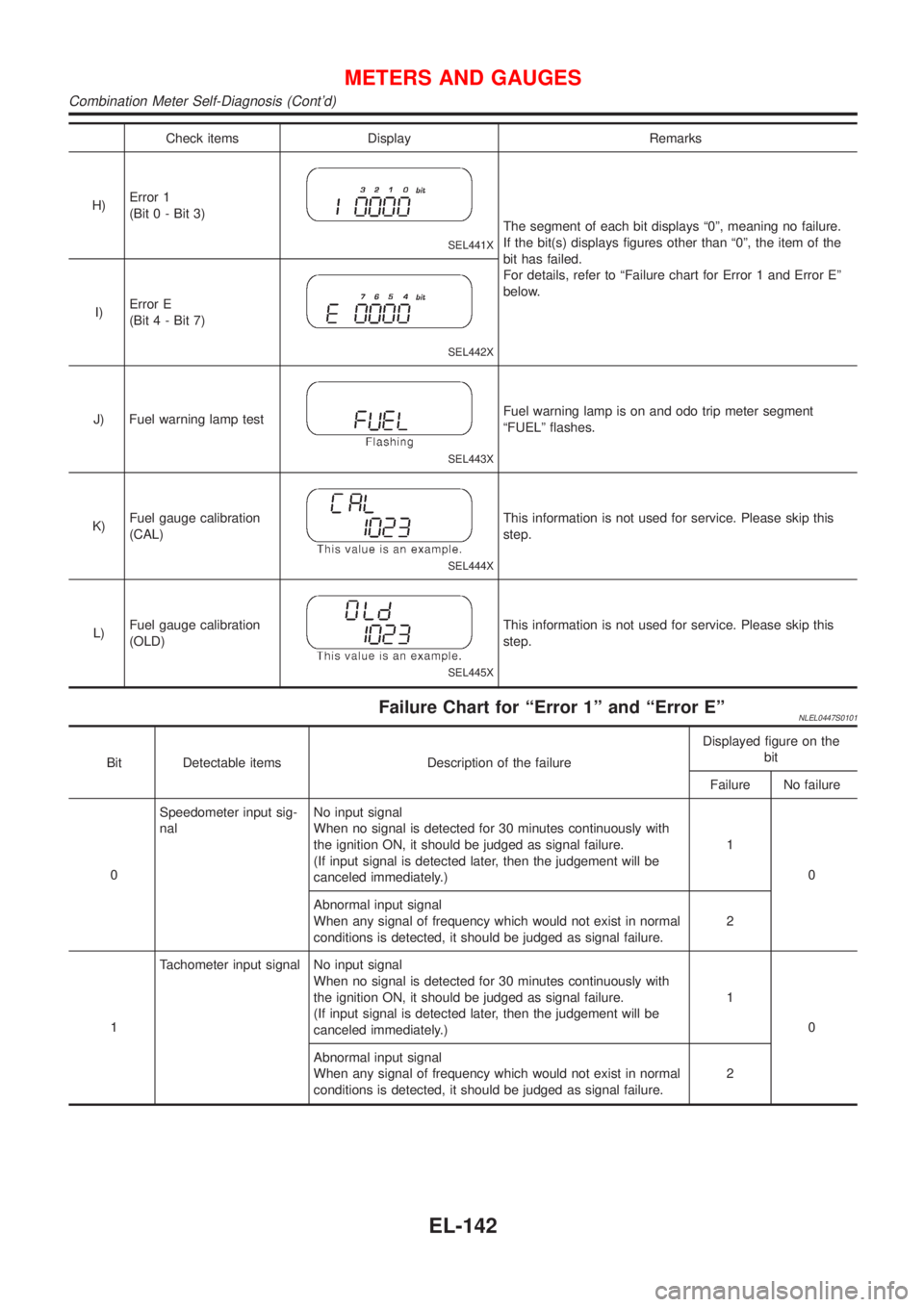
H)Error 1
(Bit 0 - Bit 3)
SEL441X
The segment of each bit displays ª0º, meaning no failure.
If the bit(s) displays figures other than ª0º, the item of the
bit has failed.
For details, refer to ªFailure chart for Error 1 and Error Eº
below.
I)Error E
(Bit 4 - Bit 7)
SEL442X
J) Fuel warning lamp test
SEL443X
Fuel warning lamp is on and odo trip meter segment
ªFUELº flashes.
K)Fuel gauge calibration
(CAL)
SEL444X
This information is not used for service. Please skip this
step.
L)Fuel gauge calibration
(OLD)
SEL445X
This information is not used for service. Please skip this
step.
Failure Chart for ªError 1º and ªError EºNLEL0447S0101
Bit Detectable items Description of the failureDisplayed figure on the
bit
Failure No failure
0Speedometer input sig-
nalNo input signal
When no signal is detected for 30 minutes continuously with
the ignition ON, it should be judged as signal failure.
(If input signal is detected later, then the judgement will be
canceled immediately.)1
0
Abnormal input signal
When any signal of frequency which would not exist in normal
conditions is detected, it should be judged as signal failure.2
1Tachometer input signal No input signal
When no signal is detected for 30 minutes continuously with
the ignition ON, it should be judged as signal failure.
(If input signal is detected later, then the judgement will be
canceled immediately.)1
0
Abnormal input signal
When any signal of frequency which would not exist in normal
conditions is detected, it should be judged as signal failure.2
METERS AND GAUGES
Combination Meter Self-Diagnosis (Cont'd)
EL-142
Page 1874 of 3051
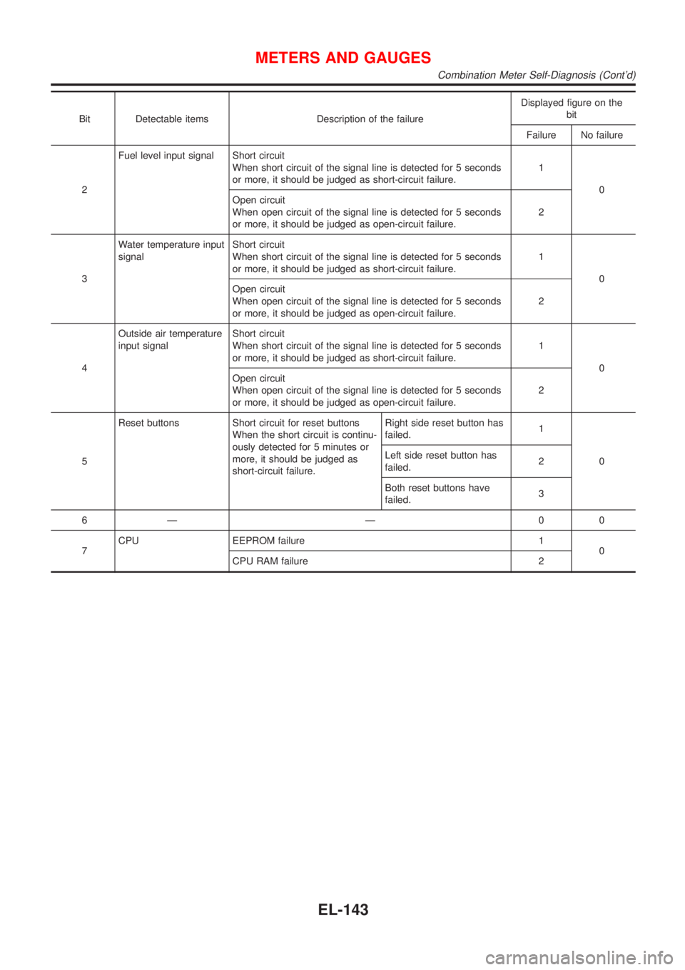
Bit Detectable items Description of the failureDisplayed figure on the
bit
Failure No failure
2Fuel level input signal Short circuit
When short circuit of the signal line is detected for 5 seconds
or more, it should be judged as short-circuit failure.1
0
Open circuit
When open circuit of the signal line is detected for 5 seconds
or more, it should be judged as open-circuit failure.2
3Water temperature input
signalShort circuit
When short circuit of the signal line is detected for 5 seconds
or more, it should be judged as short-circuit failure.1
0
Open circuit
When open circuit of the signal line is detected for 5 seconds
or more, it should be judged as open-circuit failure.2
4Outside air temperature
input signalShort circuit
When short circuit of the signal line is detected for 5 seconds
or more, it should be judged as short-circuit failure.1
0
Open circuit
When open circuit of the signal line is detected for 5 seconds
or more, it should be judged as open-circuit failure.2
5Reset buttons Short circuit for reset buttons
When the short circuit is continu-
ously detected for 5 minutes or
more, it should be judged as
short-circuit failure.Right side reset button has
failed.1
0 Left side reset button has
failed.2
Both reset buttons have
failed.3
6Ð Ð 00
7CPU EEPROM failure 1
0
CPU RAM failure 2
METERS AND GAUGES
Combination Meter Self-Diagnosis (Cont'd)
EL-143
Page 1875 of 3051
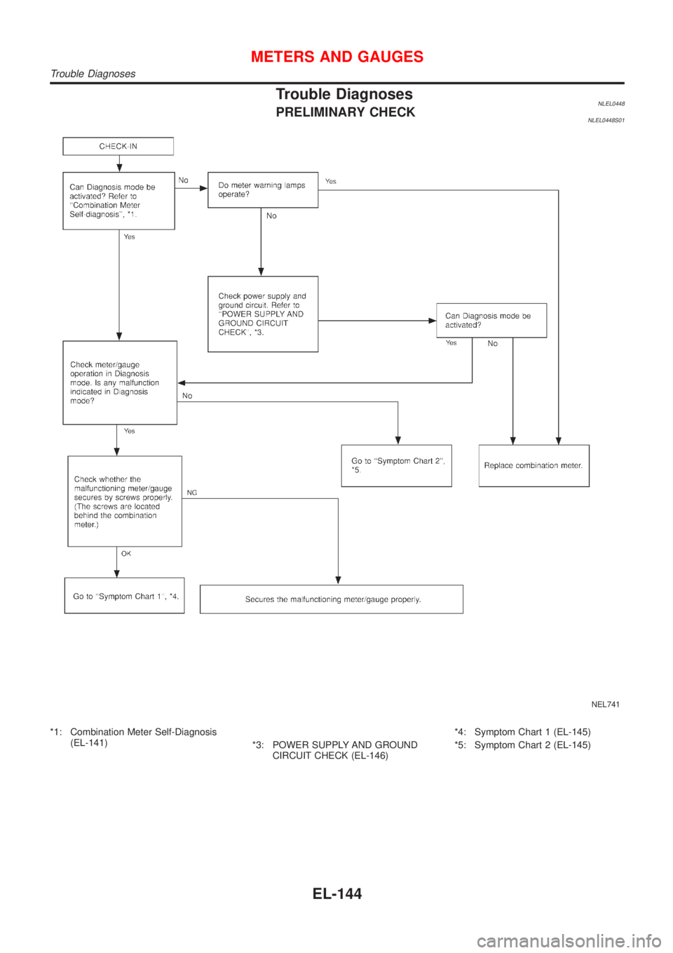
Trouble DiagnosesNLEL0448PRELIMINARY CHECKNLEL0448S01
NEL741
*1: Combination Meter Self-Diagnosis
(EL-141)
*3: POWER SUPPLY AND GROUND
CIRCUIT CHECK (EL-146)*4: Symptom Chart 1 (EL-145)
*5: Symptom Chart 2 (EL-145)
METERS AND GAUGES
Trouble Diagnoses
EL-144
Page 1876 of 3051
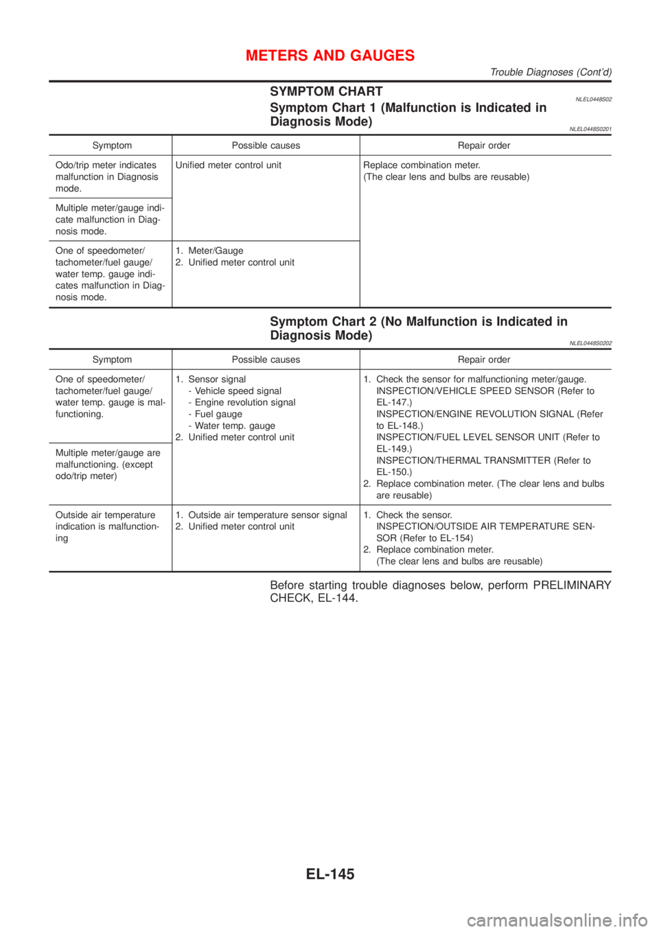
SYMPTOM CHARTNLEL0448S02Symptom Chart 1 (Malfunction is Indicated in
Diagnosis Mode)
NLEL0448S0201
Symptom Possible causes Repair order
Odo/trip meter indicates
malfunction in Diagnosis
mode.Unified meter control unit Replace combination meter.
(The clear lens and bulbs are reusable)
Multiple meter/gauge indi-
cate malfunction in Diag-
nosis mode.
One of speedometer/
tachometer/fuel gauge/
water temp. gauge indi-
cates malfunction in Diag-
nosis mode.1. Meter/Gauge
2. Unified meter control unit
Symptom Chart 2 (No Malfunction is Indicated in
Diagnosis Mode)
NLEL0448S0202
Symptom Possible causes Repair order
One of speedometer/
tachometer/fuel gauge/
water temp. gauge is mal-
functioning.1. Sensor signal
- Vehicle speed signal
- Engine revolution signal
- Fuel gauge
- Water temp. gauge
2. Unified meter control unit1. Check the sensor for malfunctioning meter/gauge.
INSPECTION/VEHICLE SPEED SENSOR (Refer to
EL-147.)
INSPECTION/ENGINE REVOLUTION SIGNAL (Refer
to EL-148.)
INSPECTION/FUEL LEVEL SENSOR UNIT (Refer to
EL-149.)
INSPECTION/THERMAL TRANSMITTER (Refer to
EL-150.)
2. Replace combination meter. (The clear lens and bulbs
are reusable) Multiple meter/gauge are
malfunctioning. (except
odo/trip meter)
Outside air temperature
indication is malfunction-
ing1. Outside air temperature sensor signal
2. Unified meter control unit1. Check the sensor.
INSPECTION/OUTSIDE AIR TEMPERATURE SEN-
SOR (Refer to EL-154)
2. Replace combination meter.
(The clear lens and bulbs are reusable)
Before starting trouble diagnoses below, perform PRELIMINARY
CHECK, EL-144.
METERS AND GAUGES
Trouble Diagnoses (Cont'd)
EL-145
Page 1877 of 3051
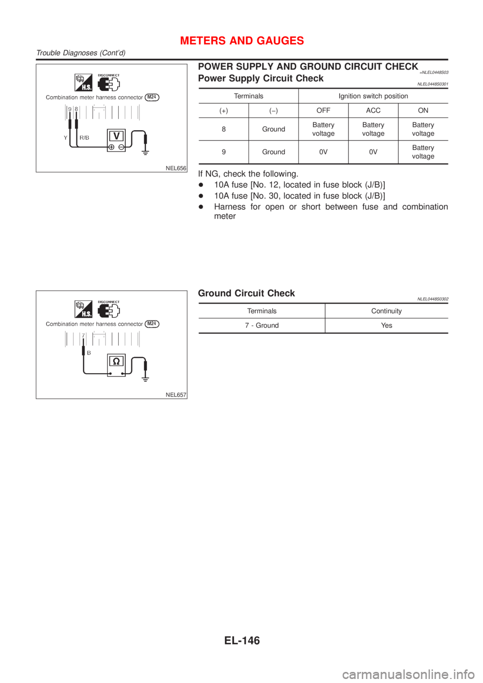
NEL656
POWER SUPPLY AND GROUND CIRCUIT CHECK=NLEL0448S03Power Supply Circuit CheckNLEL0448S0301
Terminals Ignition switch position
(+) (þ) OFF ACC ON
8 GroundBattery
voltageBattery
voltageBattery
voltage
9 Ground 0V 0VBattery
voltage
If NG, check the following.
+10A fuse [No. 12, located in fuse block (J/B)]
+10A fuse [No. 30, located in fuse block (J/B)]
+Harness for open or short between fuse and combination
meter
NEL657
Ground Circuit CheckNLEL0448S0302
Terminals Continuity
7 - Ground Yes
METERS AND GAUGES
Trouble Diagnoses (Cont'd)
EL-146
Page 1878 of 3051
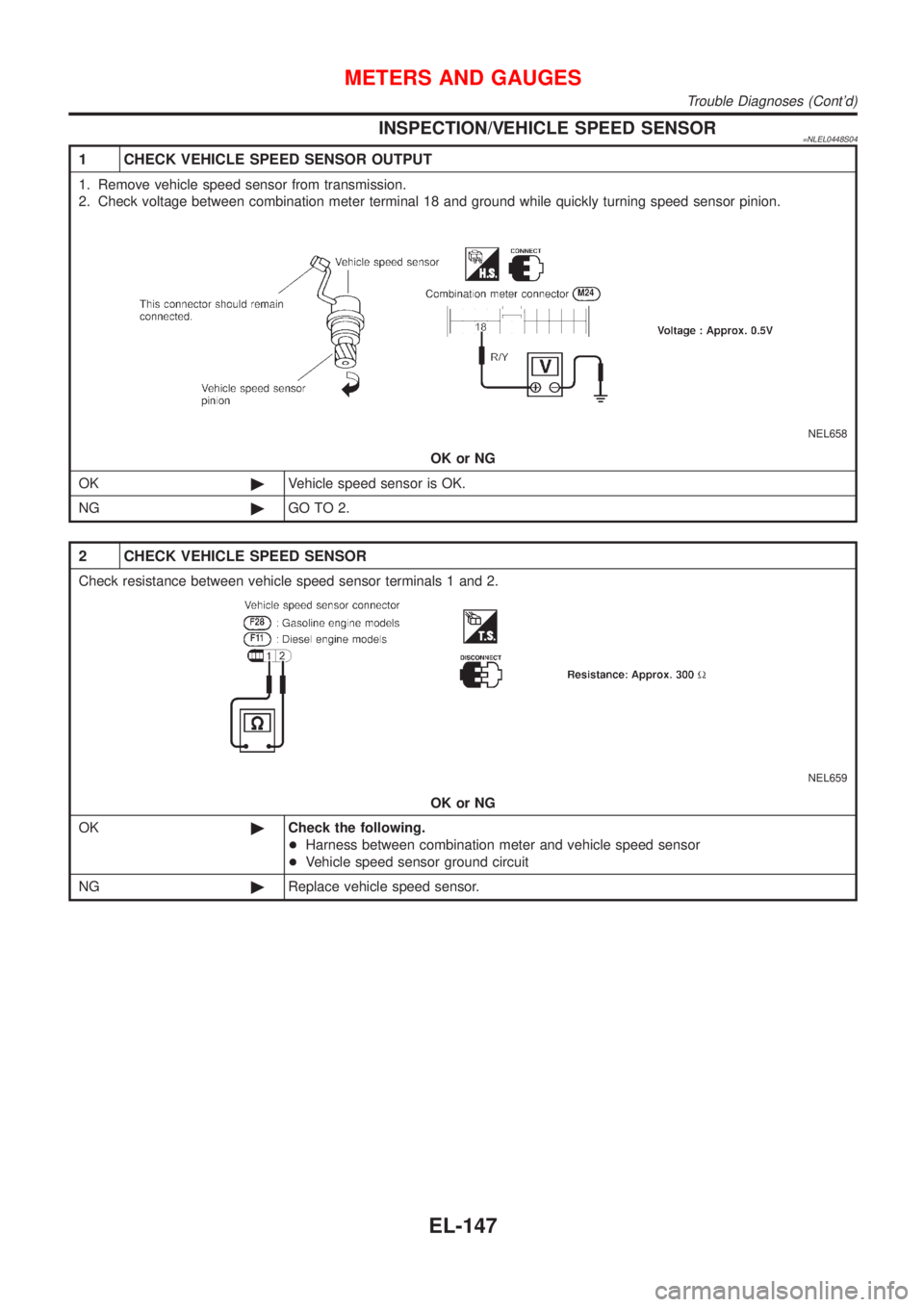
INSPECTION/VEHICLE SPEED SENSOR=NLEL0448S04
1 CHECK VEHICLE SPEED SENSOR OUTPUT
1. Remove vehicle speed sensor from transmission.
2. Check voltage between combination meter terminal 18 and ground while quickly turning speed sensor pinion.
NEL658
OK or NG
OK©Vehicle speed sensor is OK.
NG©GO TO 2.
2 CHECK VEHICLE SPEED SENSOR
Check resistance between vehicle speed sensor terminals 1 and 2.
NEL659
OK or NG
OK©Check the following.
+Harness between combination meter and vehicle speed sensor
+Vehicle speed sensor ground circuit
NG©Replace vehicle speed sensor.
METERS AND GAUGES
Trouble Diagnoses (Cont'd)
EL-147
Page 1879 of 3051
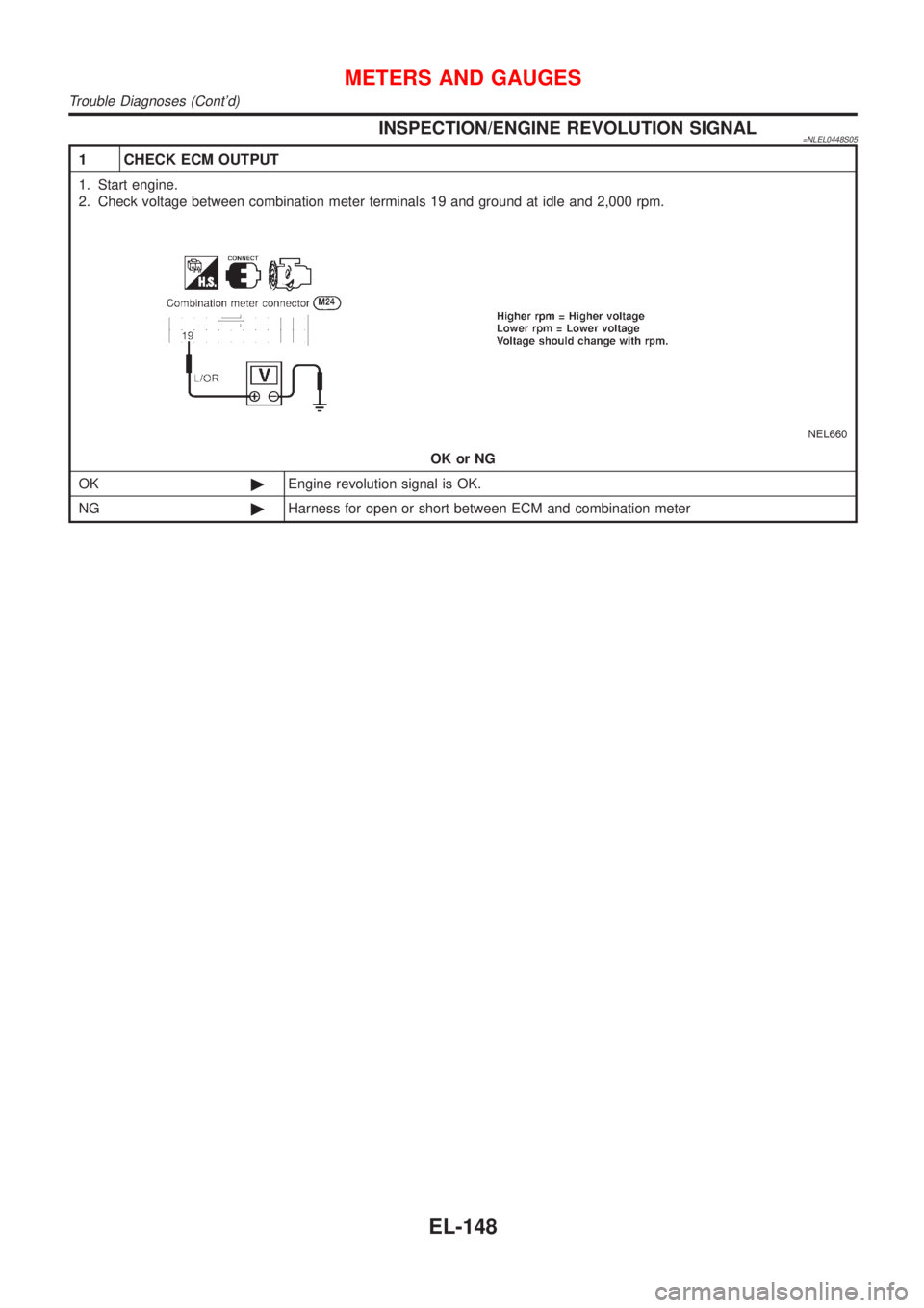
INSPECTION/ENGINE REVOLUTION SIGNAL=NLEL0448S05
1 CHECK ECM OUTPUT
1. Start engine.
2. Check voltage between combination meter terminals 19 and ground at idle and 2,000 rpm.
NEL660
OK or NG
OK©Engine revolution signal is OK.
NG©Harness for open or short between ECM and combination meter
METERS AND GAUGES
Trouble Diagnoses (Cont'd)
EL-148
Page 1880 of 3051
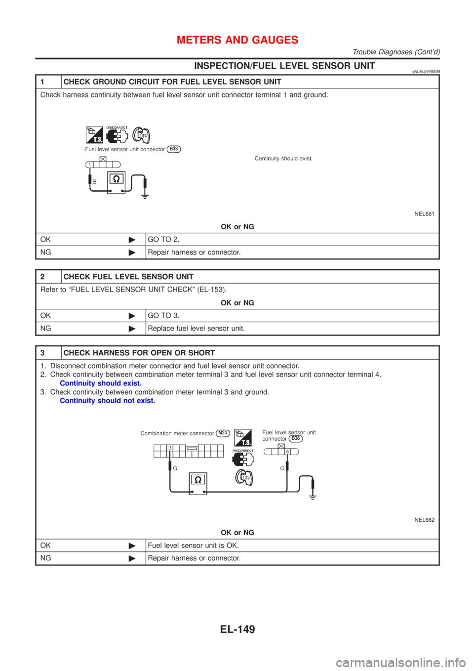
INSPECTION/FUEL LEVEL SENSOR UNIT=NLEL0448S06
1 CHECK GROUND CIRCUIT FOR FUEL LEVEL SENSOR UNIT
Check harness continuity between fuel level sensor unit connector terminal 1 and ground.
NEL661
OK or NG
OK©GO TO 2.
NG©Repair harness or connector.
2 CHECK FUEL LEVEL SENSOR UNIT
Refer to ªFUEL LEVEL SENSOR UNIT CHECKº (EL-153).
OK or NG
OK©GO TO 3.
NG©Replace fuel level sensor unit.
3 CHECK HARNESS FOR OPEN OR SHORT
1. Disconnect combination meter connector and fuel level sensor unit connector.
2. Check continuity between combination meter terminal 3 and fuel level sensor unit connector terminal 4.
Continuity should exist.
3. Check continuity between combination meter terminal 3 and ground.
Continuity should not exist.
NEL662
OK or NG
OK©Fuel level sensor unit is OK.
NG©Repair harness or connector.
METERS AND GAUGES
Trouble Diagnoses (Cont'd)
EL-149