NISSAN ALMERA TINO 2001 Service Repair Manual
ALMERA TINO 2001
NISSAN
NISSAN
https://www.carmanualsonline.info/img/5/57352/w960_57352-0.png
NISSAN ALMERA TINO 2001 Service Repair Manual
Trending: weight, horn, center console, compression ratio, jump cable, brake pads, fuel type
Page 1881 of 3051
INSPECTION/THERMAL TRANSMITTER=NLEL0448S07
1 CHECK THERMAL TRANSMITTER
Refer to ªTHERMAL TRANSMITTER CHECKº (EL-153).
OK or NG
OK©GO TO 2.
NG©Replace.
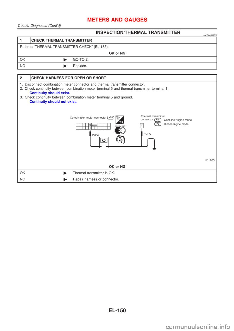
2 CHECK HARNESS FOR OPEN OR SHORT
1. Disconnect combination meter connector and thermal transmitter connector.
2. Check continuity between combination meter terminal 5 and thermal transmitter terminal 1.
Continuity should exist.
3. Check continuity between combination meter terminal 5 and ground.
Continuity should not exist.
NEL663
OK or NG
OK©Thermal transmitter is OK.
NG©Repair harness or connector.
METERS AND GAUGES
Trouble Diagnoses (Cont'd)
EL-150
Page 1882 of 3051
INSPECTION/OUTSIDE AIR TEMPERATURE SENSOR=NLEL0448S11
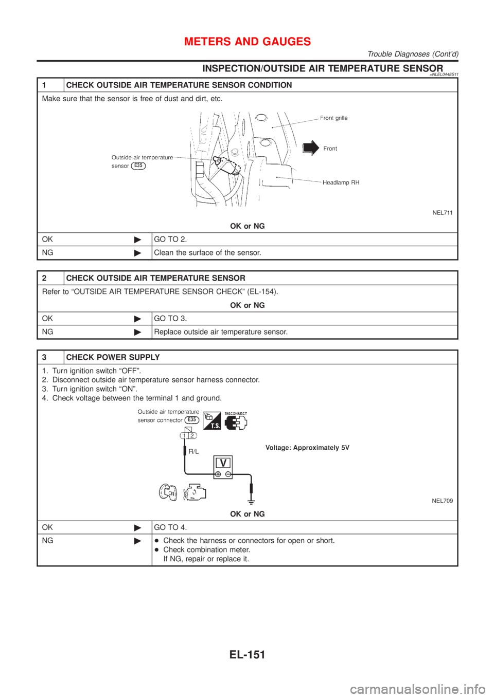
1 CHECK OUTSIDE AIR TEMPERATURE SENSOR CONDITION
Make sure that the sensor is free of dust and dirt, etc.
NEL711
OK or NG
OK©GO TO 2.
NG©Clean the surface of the sensor.
2 CHECK OUTSIDE AIR TEMPERATURE SENSOR
Refer to ªOUTSIDE AIR TEMPERATURE SENSOR CHECKº (EL-154).
OK or NG
OK©GO TO 3.
NG©Replace outside air temperature sensor.
3 CHECK POWER SUPPLY
1. Turn ignition switch ªOFFº.
2. Disconnect outside air temperature sensor harness connector.
3. Turn ignition switch ªONº.
4. Check voltage between the terminal 1 and ground.
NEL709
OK or NG
OK©GO TO 4.
NG©+Check the harness or connectors for open or short.
+Check combination meter.
If NG, repair or replace it.
METERS AND GAUGES
Trouble Diagnoses (Cont'd)
EL-151
Page 1883 of 3051
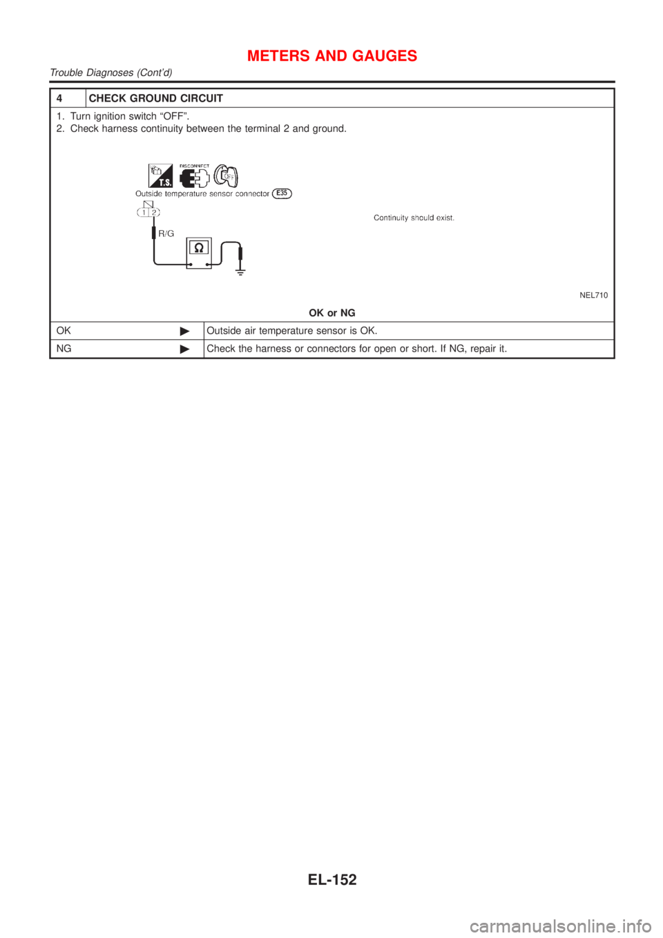
4 CHECK GROUND CIRCUIT
1. Turn ignition switch ªOFFº.
2. Check harness continuity between the terminal 2 and ground.
NEL710
OK or NG
OK©Outside air temperature sensor is OK.
NG©Check the harness or connectors for open or short. If NG, repair it.
METERS AND GAUGES
Trouble Diagnoses (Cont'd)
EL-152
Page 1884 of 3051
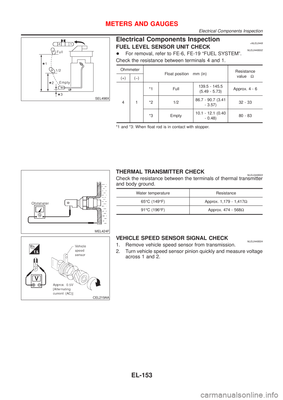
SEL498X
Electrical Components Inspection=NLEL0449FUEL LEVEL SENSOR UNIT CHECKNLEL0449S02+For removal, refer to FE-6, FE-19 ªFUEL SYSTEMº.
Check the resistance between terminals 4 and 1.
Ohmmeter
Float position mm (in)Resistance
valueW
(+) (þ)
41*1 Full139.5 - 145.5
(5.49 - 5.73)Approx.4-6
*2 1/286.7 - 90.7 (3.41
- 3.57)32-33
*3 Empty10.1 - 12.1 (0.40
- 0.48)80-83
*1 and *3: When float rod is in contact with stopper.
MEL424F
THERMAL TRANSMITTER CHECKNLEL0449S03Check the resistance between the terminals of thermal transmitter
and body ground.
Water temperature Resistance
65ÉC (149ÉF) Approx. 1,179 - 1,417W
91ÉC (196ÉF) Approx. 474 - 568W
CEL219AA
VEHICLE SPEED SENSOR SIGNAL CHECKNLEL0449S041. Remove vehicle speed sensor from transmission.
2. Turn vehicle speed sensor pinion quickly and measure voltage
across 1 and 2.
METERS AND GAUGES
Electrical Components Inspection
EL-153
Page 1885 of 3051
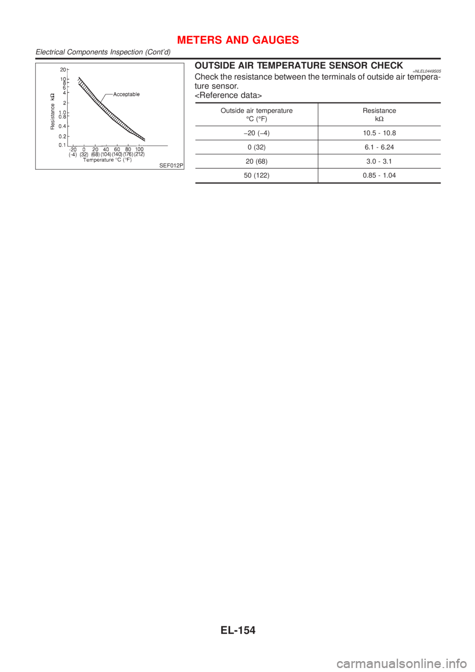
SEF012P
OUTSIDE AIR TEMPERATURE SENSOR CHECK=NLEL0449S05Check the resistance between the terminals of outside air tempera-
ture sensor.
Outside air temperature
ÉC (ÉF)Resistance
kW
þ20 (þ4) 10.5 - 10.8
0 (32) 6.1 - 6.24
20 (68) 3.0 - 3.1
50 (122) 0.85 - 1.04
METERS AND GAUGES
Electrical Components Inspection (Cont'd)
EL-154
Page 1886 of 3051
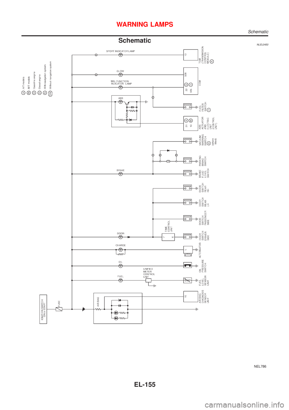
SchematicNLEL0450
NEL786
WARNING LAMPS
Schematic
EL-155
Page 1887 of 3051
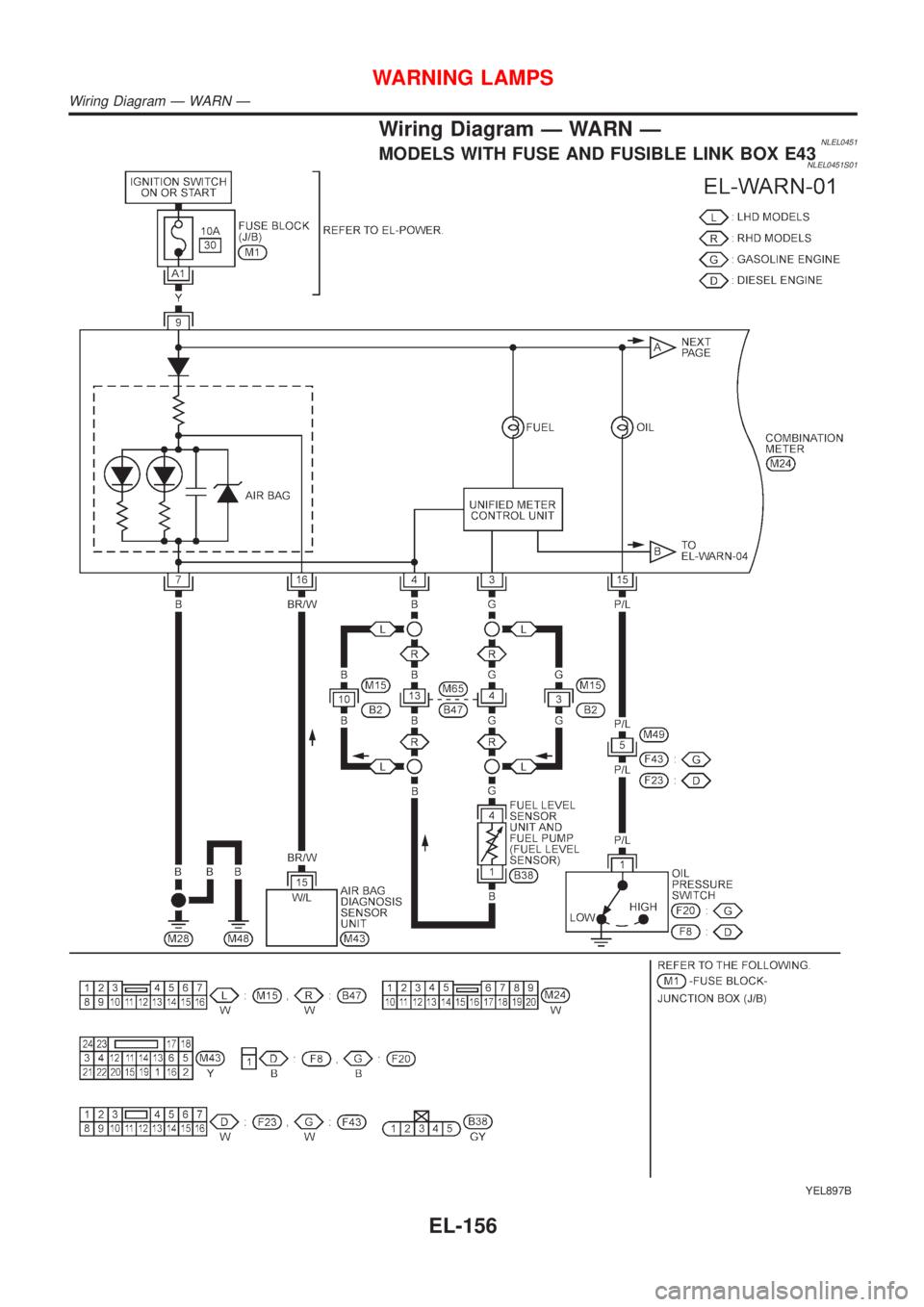
Wiring Diagram Ð WARN ÐNLEL0451MODELS WITH FUSE AND FUSIBLE LINK BOX E43NLEL0451S01
YEL897B
WARNING LAMPS
Wiring Diagram Ð WARN Ð
EL-156
Page 1888 of 3051
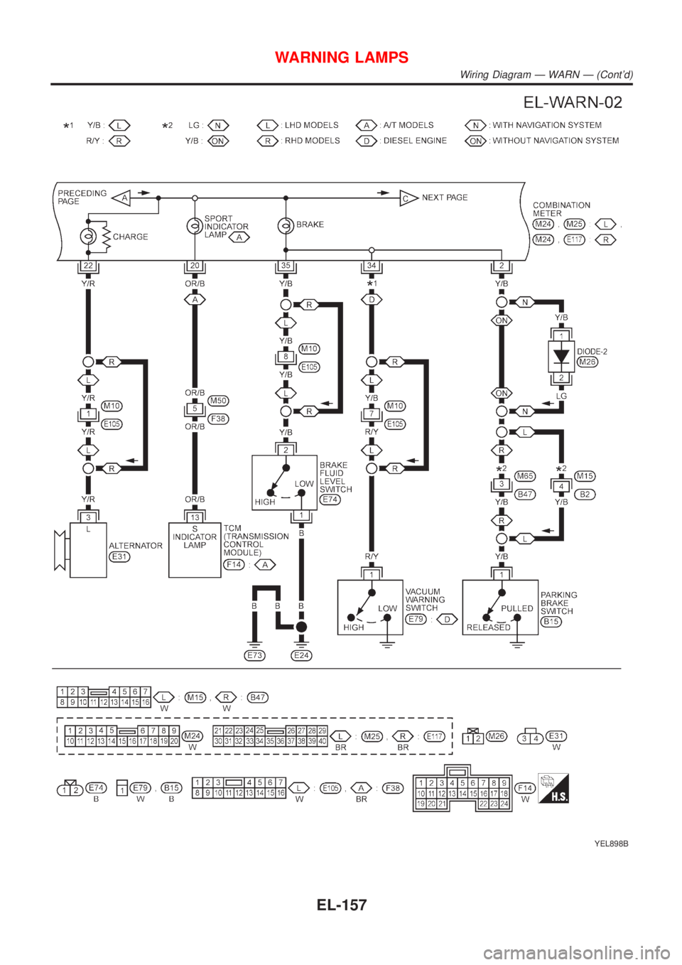
YEL898B
WARNING LAMPS
Wiring Diagram Ð WARN Ð (Cont'd)
EL-157
Page 1889 of 3051
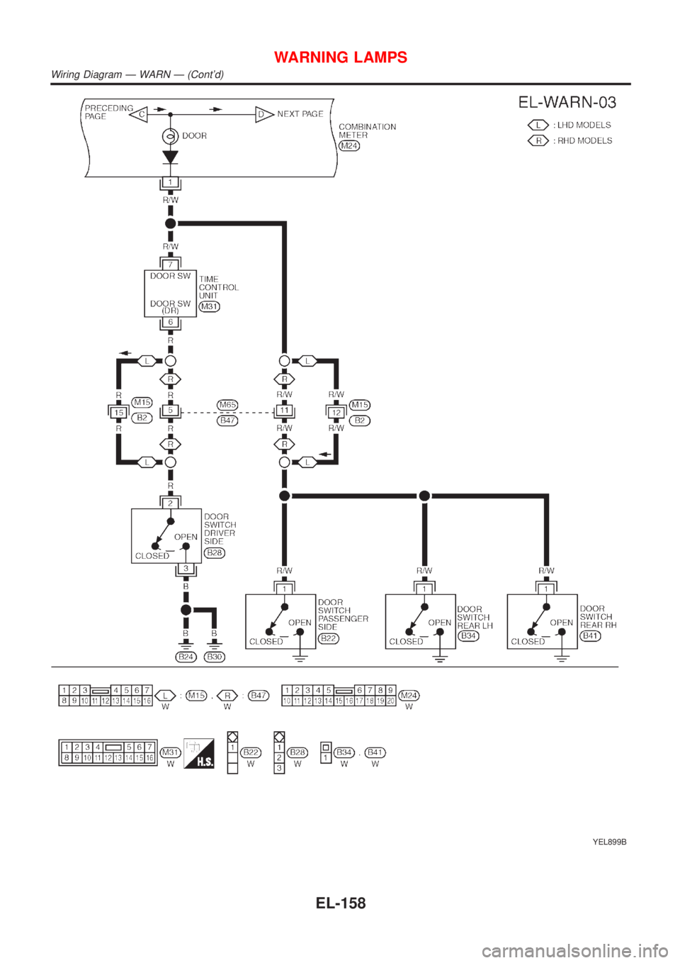
YEL899B
WARNING LAMPS
Wiring Diagram Ð WARN Ð (Cont'd)
EL-158
Page 1890 of 3051
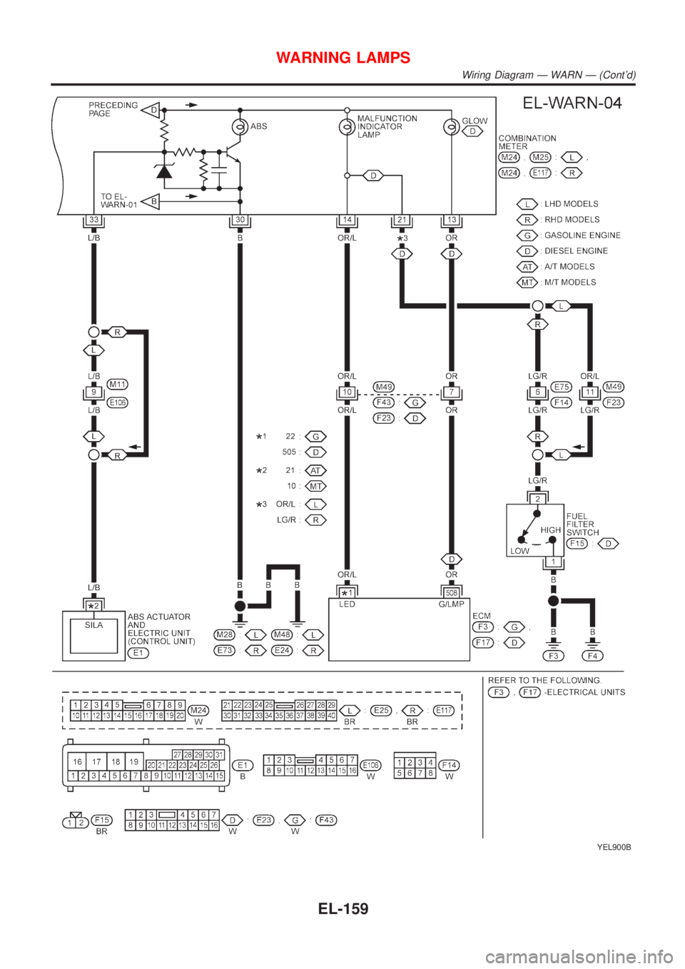
YEL900B
WARNING LAMPS
Wiring Diagram Ð WARN Ð (Cont'd)
EL-159
Trending: trunk release, run flat, ESP inoperative, tow bar, stop start, open gas tank, interior lights
