NISSAN ALMERA TINO 2001 Service Repair Manual
Manufacturer: NISSAN, Model Year: 2001, Model line: ALMERA TINO, Model: NISSAN ALMERA TINO 2001Pages: 3051, PDF Size: 46.38 MB
Page 2151 of 3051
SEL562X
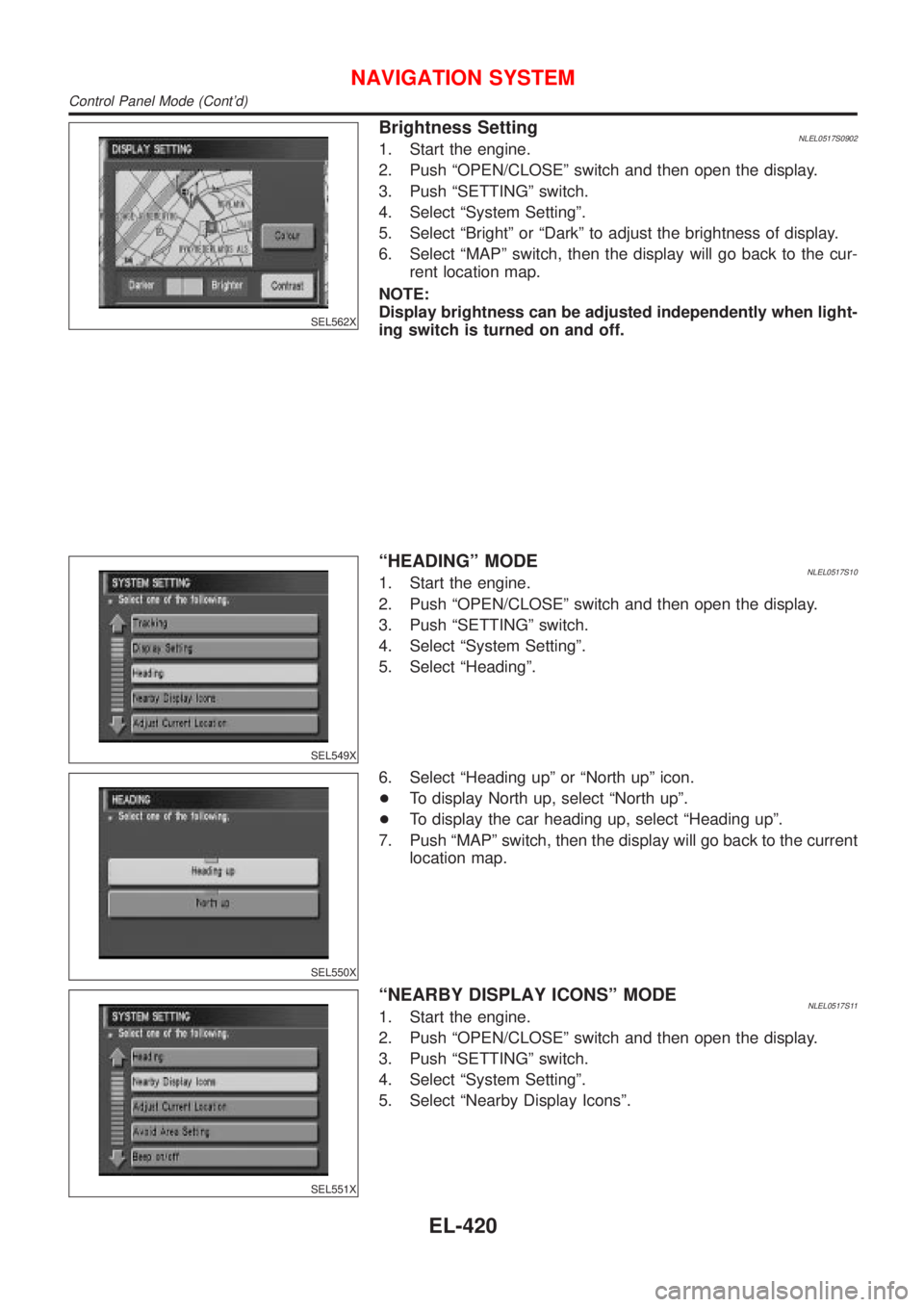
Brightness SettingNLEL0517S09021. Start the engine.
2. Push ªOPEN/CLOSEº switch and then open the display.
3. Push ªSETTINGº switch.
4. Select ªSystem Settingº.
5. Select ªBrightº or ªDarkº to adjust the brightness of display.
6. Select ªMAPº switch, then the display will go back to the cur-
rent location map.
NOTE:
Display brightness can be adjusted independently when light-
ing switch is turned on and off.
SEL549X
ªHEADINGº MODENLEL0517S101. Start the engine.
2. Push ªOPEN/CLOSEº switch and then open the display.
3. Push ªSETTINGº switch.
4. Select ªSystem Settingº.
5. Select ªHeadingº.
SEL550X
6. Select ªHeading upº or ªNorth upº icon.
+To display North up, select ªNorth upº.
+To display the car heading up, select ªHeading upº.
7. Push ªMAPº switch, then the display will go back to the current
location map.
SEL551X
ªNEARBY DISPLAY ICONSº MODENLEL0517S111. Start the engine.
2. Push ªOPEN/CLOSEº switch and then open the display.
3. Push ªSETTINGº switch.
4. Select ªSystem Settingº.
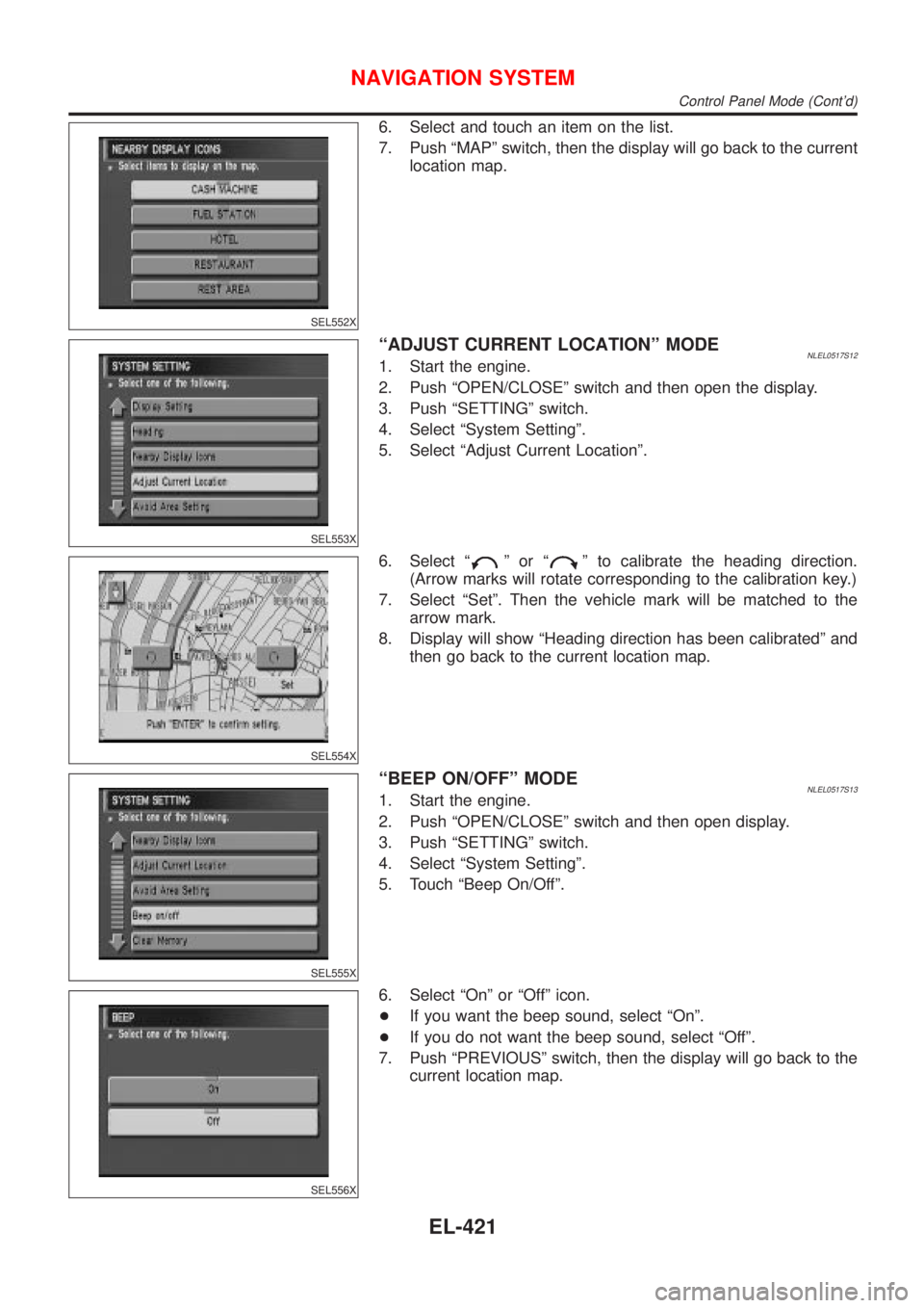
5. Select ªNearby Display Iconsº.
NAVIGATION SYSTEM
Control Panel Mode (Cont'd)
EL-420
Page 2152 of 3051
SEL552X
6. Select and touch an item on the list.
7. Push ªMAPº switch, then the display will go back to the current
location map.
SEL553X
ªADJUST CURRENT LOCATIONº MODENLEL0517S121. Start the engine.
2. Push ªOPEN/CLOSEº switch and then open the display.
3. Push ªSETTINGº switch.
4. Select ªSystem Settingº.
5. Select ªAdjust Current Locationº.
SEL554X
6. Select ªºorªº to calibrate the heading direction.
(Arrow marks will rotate corresponding to the calibration key.)
7. Select ªSetº. Then the vehicle mark will be matched to the
arrow mark.
8. Display will show ªHeading direction has been calibratedº and
then go back to the current location map.
SEL555X
ªBEEP ON/OFFº MODENLEL0517S131. Start the engine.
2. Push ªOPEN/CLOSEº switch and then open display.
3. Push ªSETTINGº switch.
4. Select ªSystem Settingº.
5. Touch ªBeep On/Offº.
SEL556X
6. Select ªOnº or ªOffº icon.
+If you want the beep sound, select ªOnº.
+If you do not want the beep sound, select ªOffº.
7. Push ªPREVIOUSº switch, then the display will go back to the
current location map.
NAVIGATION SYSTEM
Control Panel Mode (Cont'd)
EL-421
Page 2153 of 3051
SEL557X
ªCLEAR MEMORYº MODE=NLEL0517S141. Start the engine.
2. Push ªOPEN/CLOSEº switch and then open the display.
3. Push ªSETTINGº switch.
4. Select ªSystem Settingº.
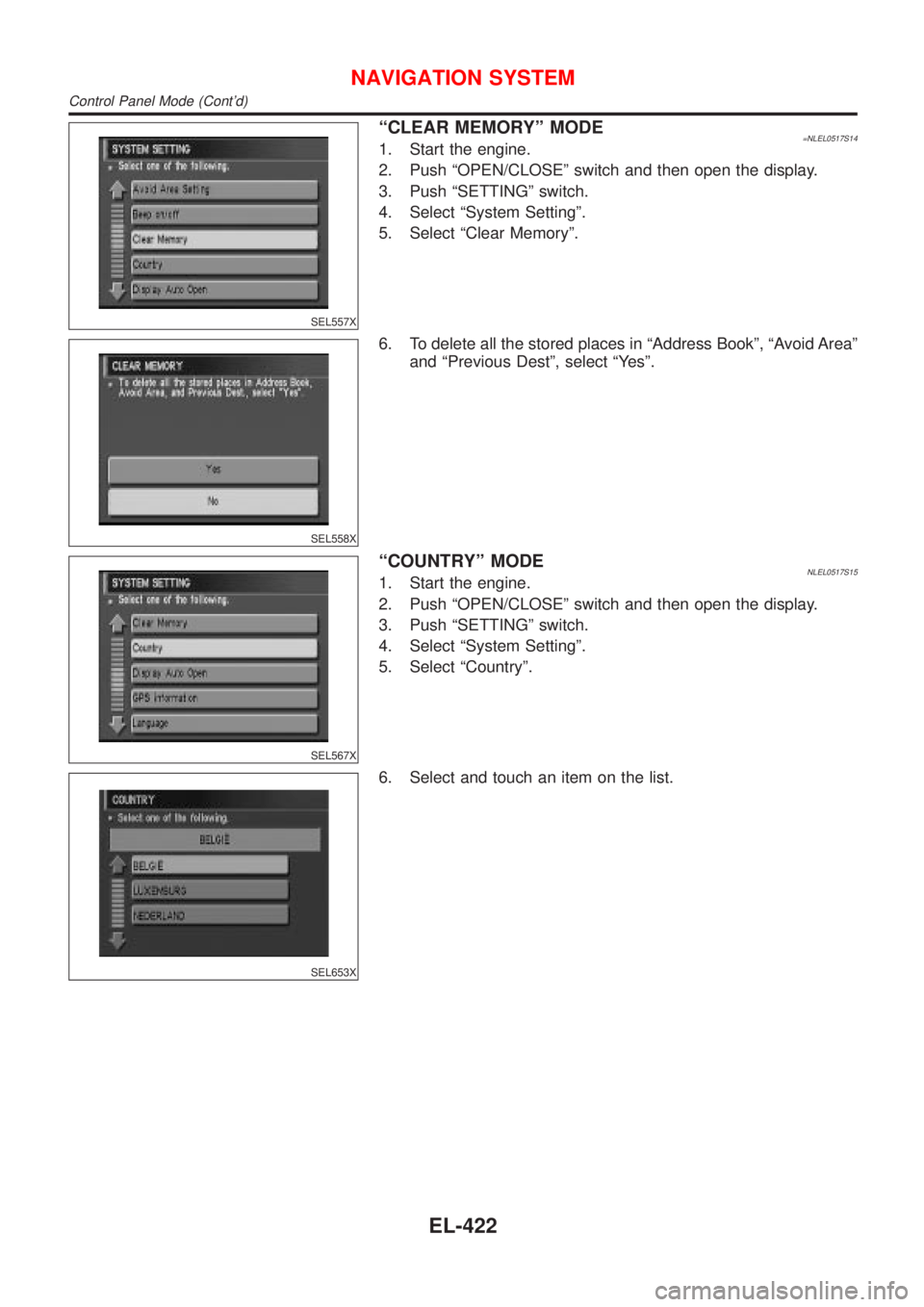
5. Select ªClear Memoryº.
SEL558X
6. To delete all the stored places in ªAddress Bookº, ªAvoid Areaº
and ªPrevious Destº, select ªYesº.
SEL567X
ªCOUNTRYº MODENLEL0517S151. Start the engine.
2. Push ªOPEN/CLOSEº switch and then open the display.
3. Push ªSETTINGº switch.
4. Select ªSystem Settingº.
5. Select ªCountryº.
SEL653X
6. Select and touch an item on the list.
NAVIGATION SYSTEM
Control Panel Mode (Cont'd)
EL-422
Page 2154 of 3051
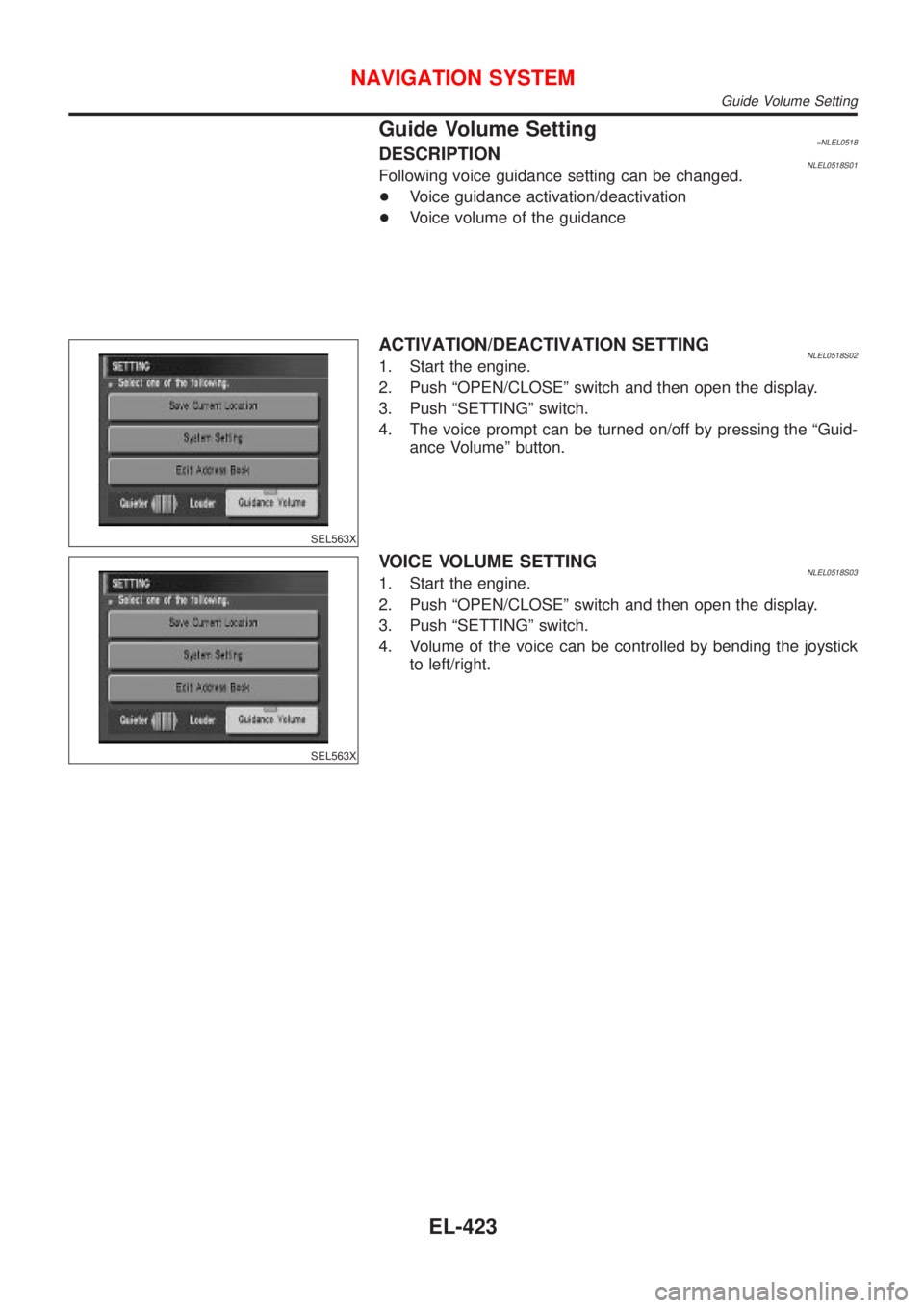
Guide Volume Setting=NLEL0518DESCRIPTIONNLEL0518S01Following voice guidance setting can be changed.
+Voice guidance activation/deactivation
+Voice volume of the guidance
SEL563X
ACTIVATION/DEACTIVATION SETTINGNLEL0518S021. Start the engine.
2. Push ªOPEN/CLOSEº switch and then open the display.
3. Push ªSETTINGº switch.
4. The voice prompt can be turned on/off by pressing the ªGuid-
ance Volumeº button.
SEL563X
VOICE VOLUME SETTINGNLEL0518S031. Start the engine.
2. Push ªOPEN/CLOSEº switch and then open the display.
3. Push ªSETTINGº switch.
4. Volume of the voice can be controlled by bending the joystick
to left/right.
NAVIGATION SYSTEM
Guide Volume Setting
EL-423
Page 2155 of 3051
Anti-theft System=NLEL0519RHD MODELSNLEL0519S01Description
By integrating the Navigation System in the vehicle's interior and linking it to the vehicle's immobilizer system,
the possibility of the Navigation unit being stolen is effectively reduced. Each time the Navigation System is
switched on, the Navigation System will start up communication with the vehicle's immobilizer control unit
(IMMU) and verify an identification code. If communication cannot be established, or the verified code is
incorrect, the Navigation System will lock up showing ªANTI-THEFT FUNCTIONº on the Navigation display.
The 4-digit PIN must be entered when the display shows ªenter your PINº at the time the vehicle is purchased.
The 4±digit PIN is required to input after disconnecting and reconnecting of battery cable or connectors for
Navigation system.
LHD MODELSNLEL0519S02Description
The 4-digit PIN must be entered when the display shows ªenter your PINº at the time the vehicle is purchased.
The 4±digit PIN is required to input after disconnecting and reconnecting of battery cable or connectors for
Navigation system.
NAVIGATION SYSTEM
Anti-theft System
EL-424
Page 2156 of 3051
SEF094Y
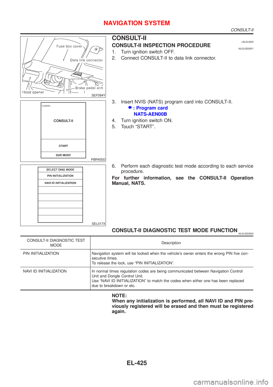
CONSULT-II=NLEL0520CONSULT-II INSPECTION PROCEDURENLEL0520S011. Turn ignition switch OFF.
2. Connect CONSULT-II to data link connector.
PBR455D
3. Insert NVIS (NATS) program card into CONSULT-II.
: Program card
NATS-AEN00B
4. Turn ignition switch ON.
5. Touch ªSTARTº.
SEL517X
6. Perform each diagnostic test mode according to each service
procedure.
For further information, see the CONSULT-II Operation
Manual, NATS.
CONSULT-II DIAGNOSTIC TEST MODE FUNCTIONNLEL0520S02
CONSULT-II DIAGNOSTIC TEST
MODEDescription
PIN INITIALIZATION Navigation system will be locked when the vehicle's owner enters the wrong PIN five con-
secutive times.
To release the lock, use ªPIN INITIALIZATIONº.
NAVI ID INITIALIZATION In normal times regulation codes are being communicated between Navigation Control
Unit and Dongle Control Unit.
Use ªNAVI ID INITIALIZATIONº to match the codes when either one has been replaced
due to breakdown or etc.
NOTE:
When any initialization is performed, all NAVI ID and PIN pre-
viously registered will be erased and then must be registered
again.
NAVIGATION SYSTEM
CONSULT-II
EL-425
Page 2157 of 3051
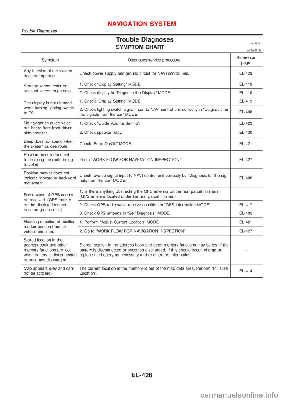
Trouble Diagnoses=NLEL0521SYMPTOM CHARTNLEL0521S01
Symptom Diagnoses/service procedureReference
page
Any function of the system
does not operate.Check power supply and ground circuit for NAVI control unit. EL-429
Strange screen color or
unusual screen brightness.1. Check ªDisplay Settingº MODE. EL-419
2. Check display in ªDiagnose the Displayº MODE. EL-410
The display is not dimmed
when turning lighting switch
to ON.1. Check ªDisplay Settingº MODE. EL-419
2. Check lighting switch signal input to NAVI control unit correctly in ªDiagnosis for
the signals from the carº MODE.EL-408
No navigation guide voice
are heard from front driver
side speaker.1. Check ªGuide Volume Settingº. EL-423
2. Check speaker relay. EL-430
Beep does not sound when
the system guides route.Check ªBeep On/Offº MODE. EL-421
Position marker does not
trace along the route being
traveled.Go to ªWORK FLOW FOR NAVIGATION INSPECTIONº. EL-427
Position marker does not
indicate forward or backward
movement.Check reverse signal input to NAVI control unit correctly by ªDiagnosis for the sig-
nals from the carº MODE.EL-408
Radio wave of GPS cannot
be received. (GPS marker
on the display does not
become green color.)1. Is there anything obstructing the GPS antenna on the rear parcel finisher?
(GPS antenna located under the rear parcel finisher.)Ð
2. Check GPS radio wave receive condition in ªGPS Information MODEº. EL-417
3. Check GPS antenna in ªSelf Diagnosisº MODE. EL-402
Heading direction of position
marker does not match
vehicle direction.1. Perform ªAdjust Current Locationº MODE. EL-421
2. Go to ªWORK FLOW FOR NAVIGATION INSPECTIONº. EL-427
Stored location in the
address book and other
memory functions are lost
when battery is disconnected
or becomes discharged.Stored location in the address book and other memory functions may be lost if the
battery is disconnected or becomes discharged. If this should occur, charge or
replace the battery as necessary and re-enter the information.Ð
Map appears grey and can-
not be scrolled.The current location in the memory is out of the map data area. Perform ªInitialize
Locationº.EL-414
NAVIGATION SYSTEM
Trouble Diagnoses
EL-426
Page 2158 of 3051
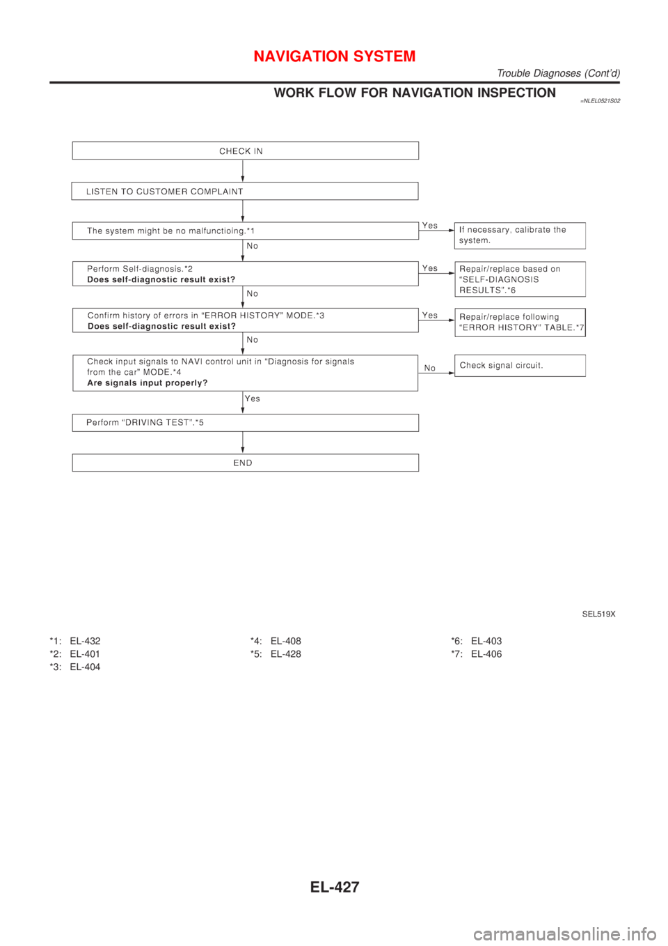
WORK FLOW FOR NAVIGATION INSPECTION=NLEL0521S02
SEL519X
*1: EL-432
*2: EL-401
*3: EL-404*4: EL-408
*5: EL-428*6: EL-403
*7: EL-406
NAVIGATION SYSTEM
Trouble Diagnoses (Cont'd)
EL-427
Page 2159 of 3051
DRIVING TEST=NLEL0521S03During the driving test, diagnose the system by checking the dif-
ference of symptoms with each sensor ON or OFF.
Test Pattern 1NLEL0521S0301Test method in which current position adjustment is not made
according to GPS data.
+Remove the GPS antenna connector from the NAVI control
unit. Drive the vehicle.
Before driving the vehicle, perform ªAdjust Current Locationº
MODE (EL-421).
Test Pattern 2NLEL0521S0302Test procedure in which map matching is not used.
+Before driving the vehicle, perform ªAdjust Current Locationº
MODE (EL-421). With the ignition switch OFF and the map
CD-ROM removed from the NAVI control unit, drive the
vehicle. After driving the vehicle, reinstall the map CD-ROM.
Compare the saved driving tracks for the vehicle's current loca-
tion with roads on the map.
ExampleNLEL0521S0303
map matching function or the GPS function.>
®Perform test pattern 1.
®Perform test patterns 1 and 2.
+Compare the map and the saved driving tracks. The precision
of the saved driving tracks is within several hundred meters.
®Perform test patterns 1 and 2.
+Make adjustments by driving the vehicle over a known course
(highway or other road where distances are clearly marked).
Calibrate the distance against the known distance. Use the
formula below.
Calibration value = Screen display distance/Actual distance
NAVIGATION SYSTEM
Trouble Diagnoses (Cont'd)
EL-428
Page 2160 of 3051
NEL705
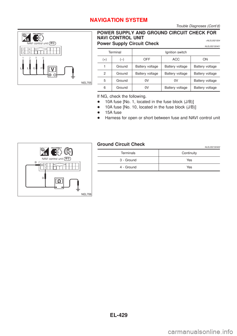
POWER SUPPLY AND GROUND CIRCUIT CHECK FOR
NAVI CONTROL UNIT
=NLEL0521S04Power Supply Circuit CheckNLEL0521S0401
Terminal Ignition switch
(+) (þ) OFF ACC ON
1 Ground Battery voltage Battery voltage Battery voltage
2 Ground Battery voltage Battery voltage Battery voltage
5 Ground 0V 0V Battery voltage
6 Ground 0V Battery voltage Battery voltage
If NG, check the following.
+10A fuse [No. 1, located in the fuse block (J/B)]
+10A fuse [No. 10, located in the fuse block (J/B)]
+15A fuse
+Harness for open or short between fuse and NAVI control unit
NEL706
Ground Circuit CheckNLEL0521S0402
Terminals Continuity
3 - Ground Yes
4 - Ground Yes
NAVIGATION SYSTEM
Trouble Diagnoses (Cont'd)
EL-429