NISSAN ALMERA TINO 2001 Service Repair Manual
ALMERA TINO 2001
NISSAN
NISSAN
https://www.carmanualsonline.info/img/5/57352/w960_57352-0.png
NISSAN ALMERA TINO 2001 Service Repair Manual
Trending: manual transmission, oil viscosity, fuel cap release, jacking points, oil, jump cable, brake
Page 801 of 3051
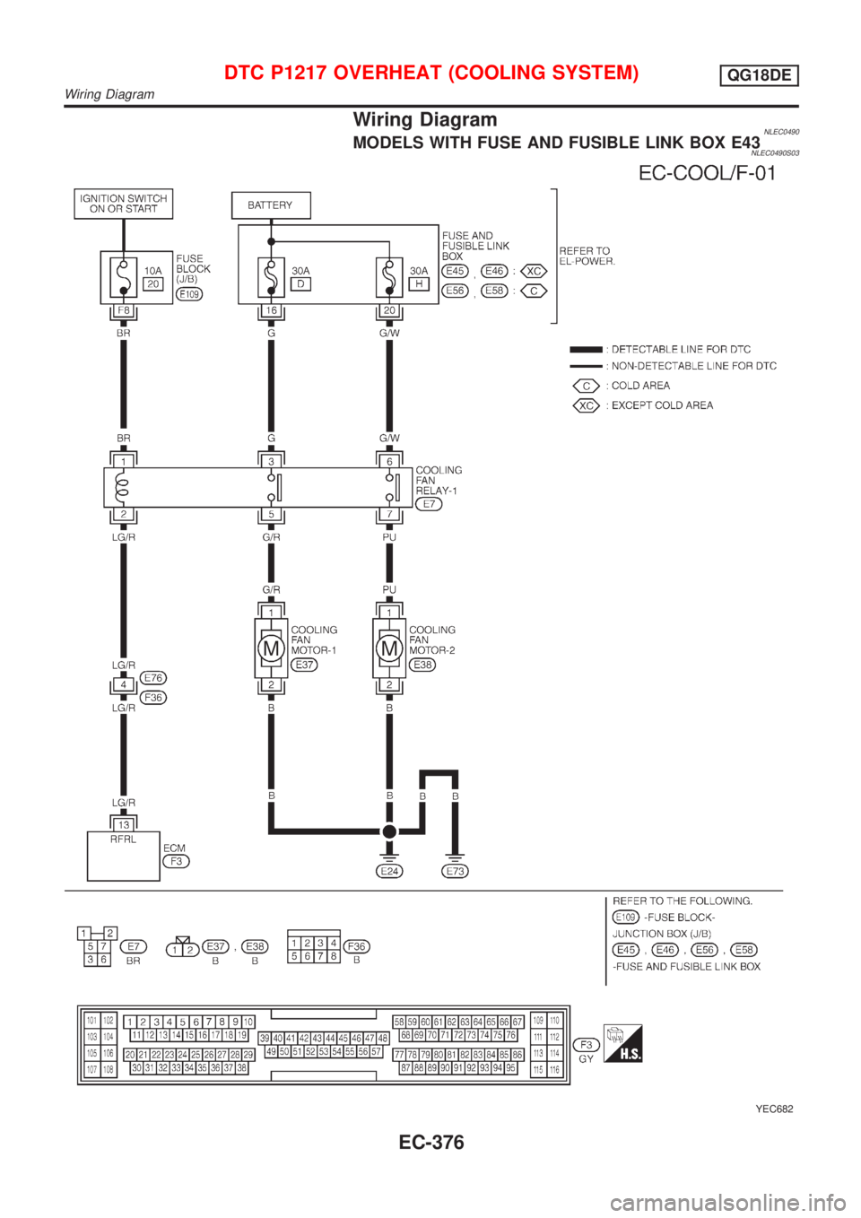
Wiring DiagramNLEC0490MODELS WITH FUSE AND FUSIBLE LINK BOX E43NLEC0490S03
YEC682
DTC P1217 OVERHEAT (COOLING SYSTEM)QG18DE
Wiring Diagram
EC-376
Page 802 of 3051
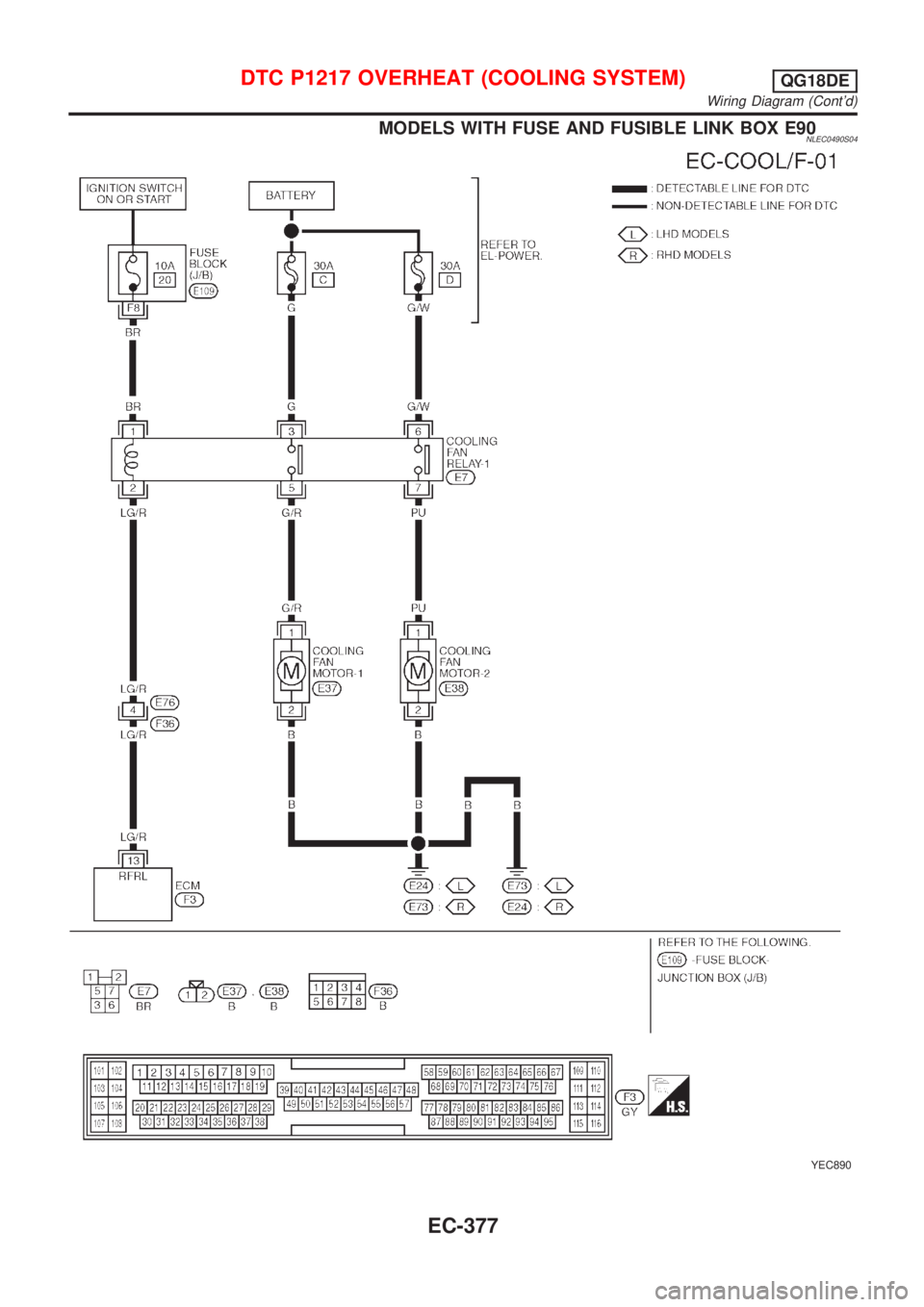
MODELS WITH FUSE AND FUSIBLE LINK BOX E90NLEC0490S04
YEC890
DTC P1217 OVERHEAT (COOLING SYSTEM)QG18DE
Wiring Diagram (Cont'd)
EC-377
Page 803 of 3051
Diagnostic ProcedureNLEC0491
1 CHECK COOLING FAN OPERATION
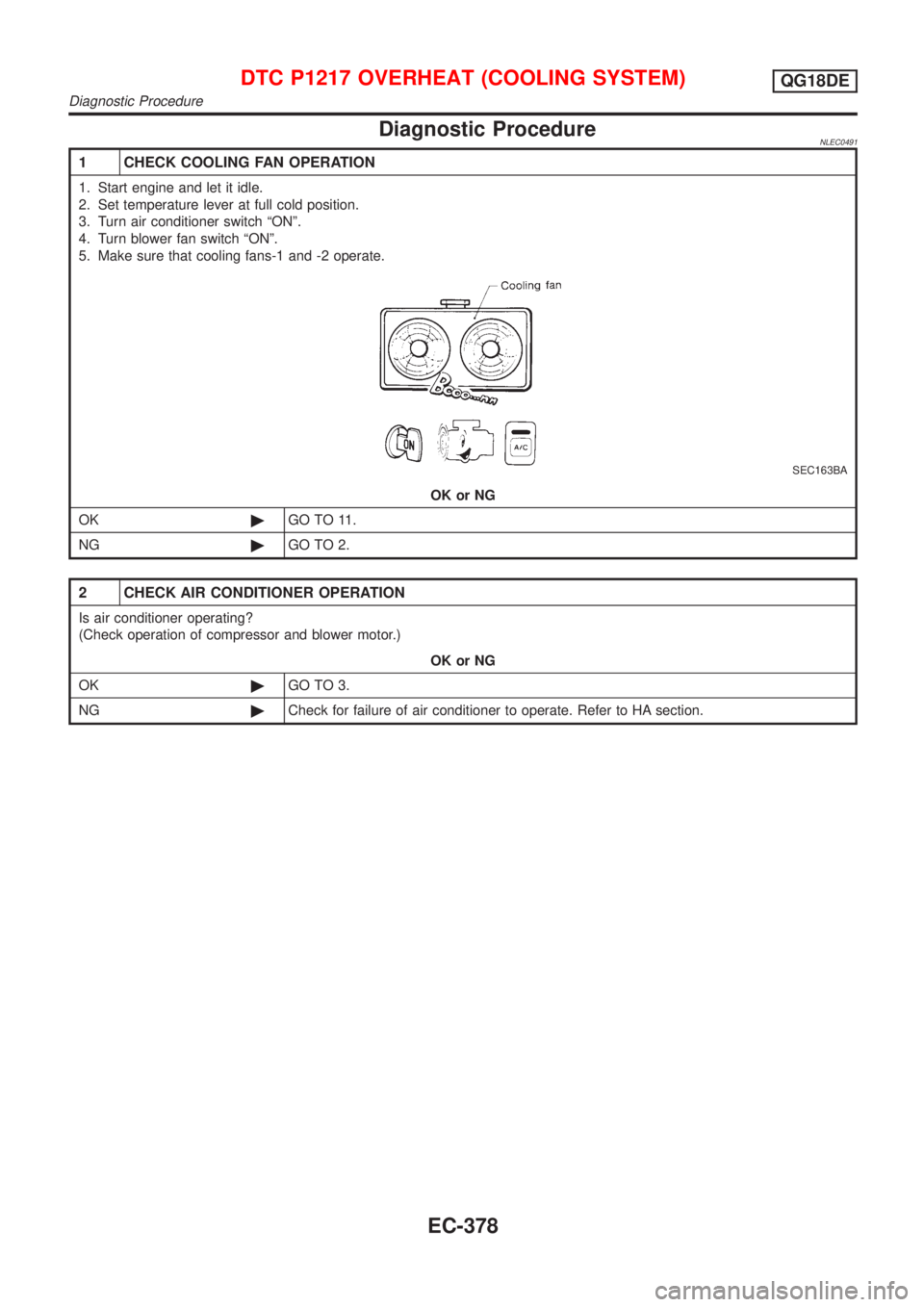
1. Start engine and let it idle.
2. Set temperature lever at full cold position.
3. Turn air conditioner switch ªONº.
4. Turn blower fan switch ªONº.
5. Make sure that cooling fans-1 and -2 operate.
SEC163BA
OK or NG
OK©GO TO 11.
NG©GO TO 2.
2 CHECK AIR CONDITIONER OPERATION
Is air conditioner operating?
(Check operation of compressor and blower motor.)
OK or NG
OK©GO TO 3.
NG©Check for failure of air conditioner to operate. Refer to HA section.
DTC P1217 OVERHEAT (COOLING SYSTEM)QG18DE
Diagnostic Procedure
EC-378
Page 804 of 3051
3 CHECK POWER SUPPLY
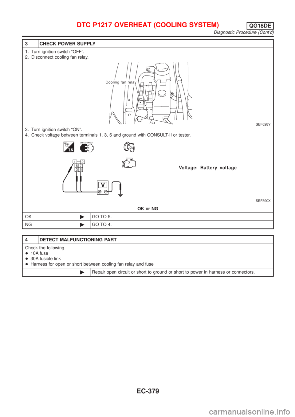
1. Turn ignition switch ªOFFº.
2. Disconnect cooling fan relay.
SEF628Y
3. Turn ignition switch ªONº.
4. Check voltage between terminals 1, 3, 6 and ground with CONSULT-II or tester.
SEF590X
OK or NG
OK©GO TO 5.
NG©GO TO 4.
4 DETECT MALFUNCTIONING PART
Check the following.
+10A fuse
+30A fusible link
+Harness for open or short between cooling fan relay and fuse
©Repair open circuit or short to ground or short to power in harness or connectors.
DTC P1217 OVERHEAT (COOLING SYSTEM)QG18DE
Diagnostic Procedure (Cont'd)
EC-379
Page 805 of 3051
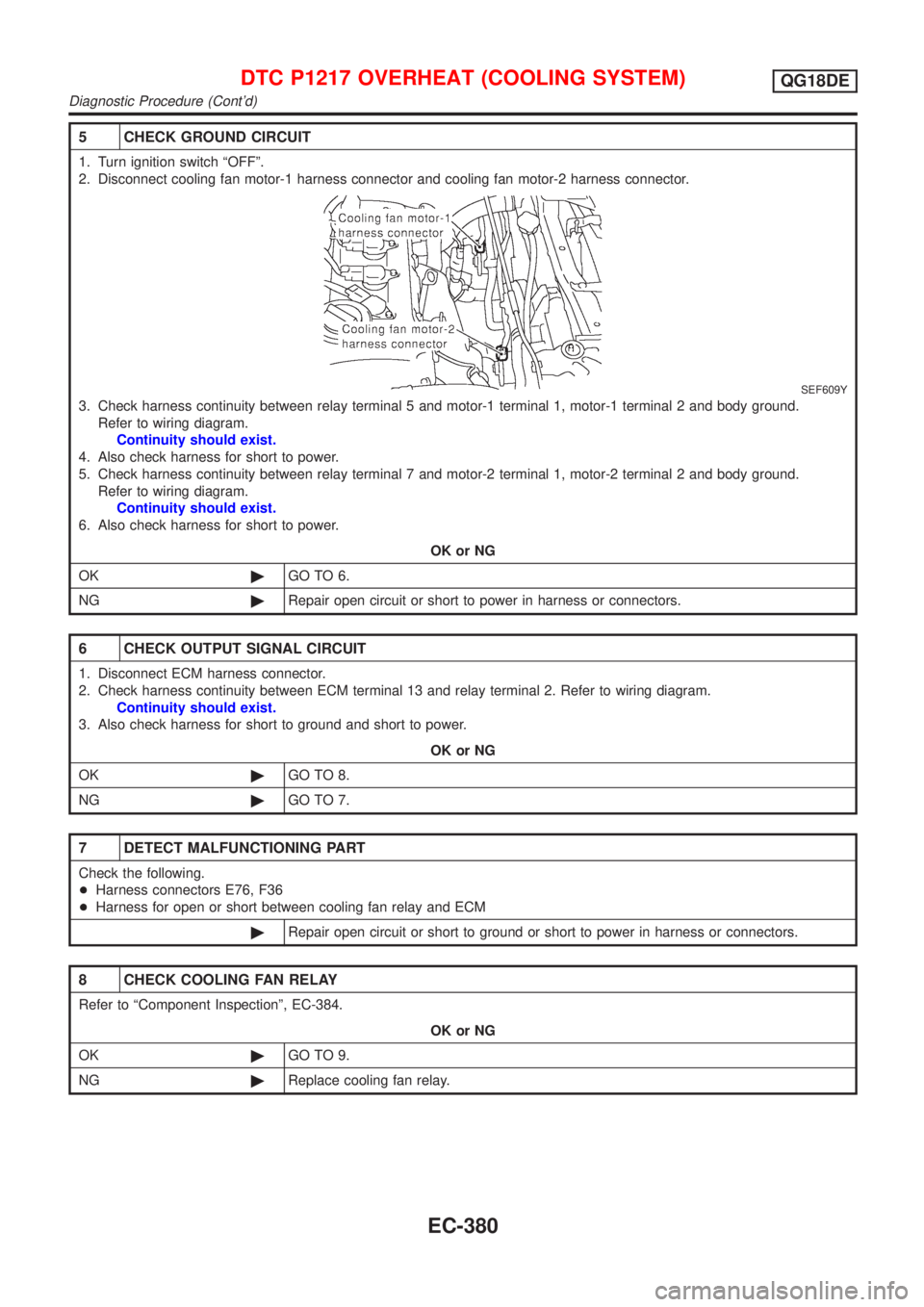
5 CHECK GROUND CIRCUIT
1. Turn ignition switch ªOFFº.
2. Disconnect cooling fan motor-1 harness connector and cooling fan motor-2 harness connector.
SEF609Y
3. Check harness continuity between relay terminal 5 and motor-1 terminal 1, motor-1 terminal 2 and body ground.
Refer to wiring diagram.
Continuity should exist.
4. Also check harness for short to power.
5. Check harness continuity between relay terminal 7 and motor-2 terminal 1, motor-2 terminal 2 and body ground.
Refer to wiring diagram.
Continuity should exist.
6. Also check harness for short to power.
OK or NG
OK©GO TO 6.
NG©Repair open circuit or short to power in harness or connectors.
6 CHECK OUTPUT SIGNAL CIRCUIT
1. Disconnect ECM harness connector.
2. Check harness continuity between ECM terminal 13 and relay terminal 2. Refer to wiring diagram.
Continuity should exist.
3. Also check harness for short to ground and short to power.
OK or NG
OK©GO TO 8.
NG©GO TO 7.
7 DETECT MALFUNCTIONING PART
Check the following.
+Harness connectors E76, F36
+Harness for open or short between cooling fan relay and ECM
©Repair open circuit or short to ground or short to power in harness or connectors.
8 CHECK COOLING FAN RELAY
Refer to ªComponent Inspectionº, EC-384.
OK or NG
OK©GO TO 9.
NG©Replace cooling fan relay.
DTC P1217 OVERHEAT (COOLING SYSTEM)QG18DE
Diagnostic Procedure (Cont'd)
EC-380
Page 806 of 3051
9 CHECK COOLING FAN MOTORS-1 AND -2
Refer to ªComponent Inspectionº, EC-384.
OK or NG
OK©GO TO 10.
NG©Replace cooling fan motors.
10 CHECK INTERMITTENT INCIDENT
Perform ªTROUBLE DIAGNOSIS FOR INTERMITTENT INCIDENTº, EC-145.
©INSPECTION END
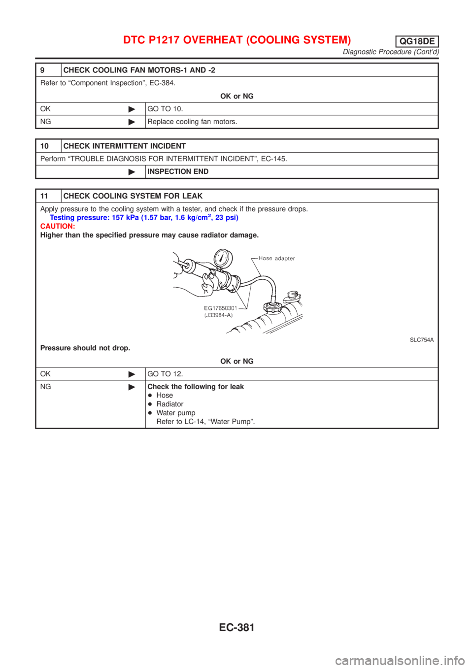
11 CHECK COOLING SYSTEM FOR LEAK
Apply pressure to the cooling system with a tester, and check if the pressure drops.
Testing pressure: 157 kPa (1.57 bar, 1.6 kg/cm2, 23 psi)
CAUTION:
Higher than the specified pressure may cause radiator damage.
SLC754A
Pressure should not drop.
OK or NG
OK©GO TO 12.
NG©Check the following for leak
+Hose
+Radiator
+Water pump
Refer to LC-14, ªWater Pumpº.
DTC P1217 OVERHEAT (COOLING SYSTEM)QG18DE
Diagnostic Procedure (Cont'd)
EC-381
Page 807 of 3051
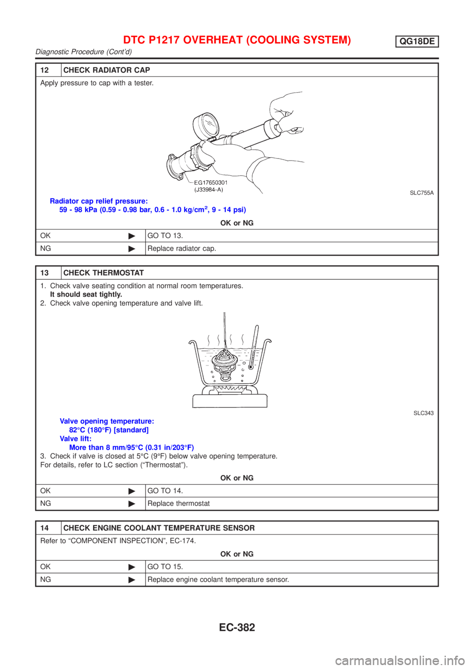
12 CHECK RADIATOR CAP
Apply pressure to cap with a tester.
SLC755A
Radiator cap relief pressure:
59 - 98 kPa (0.59 - 0.98 bar, 0.6 - 1.0 kg/cm2,9-14psi)
OK or NG
OK©GO TO 13.
NG©Replace radiator cap.
13 CHECK THERMOSTAT
1. Check valve seating condition at normal room temperatures.
It should seat tightly.
2. Check valve opening temperature and valve lift.
SLC343
Valve opening temperature:
82ÉC (180ÉF) [standard]
Valve lift:
More than 8 mm/95ÉC (0.31 in/203ÉF)
3. Check if valve is closed at 5ÉC (9ÉF) below valve opening temperature.
For details, refer to LC section (ªThermostatº).
OK or NG
OK©GO TO 14.
NG©Replace thermostat
14 CHECK ENGINE COOLANT TEMPERATURE SENSOR
Refer to ªCOMPONENT INSPECTIONº, EC-174.
OK or NG
OK©GO TO 15.
NG©Replace engine coolant temperature sensor.
DTC P1217 OVERHEAT (COOLING SYSTEM)QG18DE
Diagnostic Procedure (Cont'd)
EC-382
Page 808 of 3051
15 CHECK MAIN 12 CAUSES
If the cause cannot be isolated, go to ªMAIN 12 CAUSES OF OVERHEATINGº, EC-384.
©INSPECTION END
DTC P1217 OVERHEAT (COOLING SYSTEM)QG18DE
Diagnostic Procedure (Cont'd)
EC-383
Page 809 of 3051
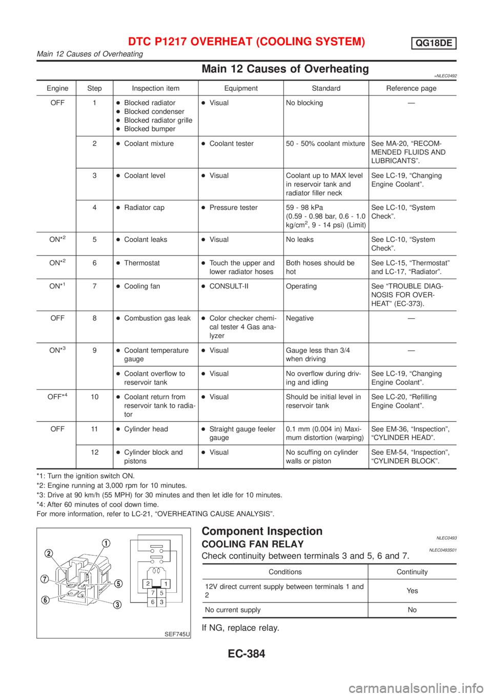
Main 12 Causes of Overheating=NLEC0492
Engine Step Inspection item Equipment Standard Reference page
OFF 1+Blocked radiator
+Blocked condenser
+Blocked radiator grille
+Blocked bumper+Visual No blocking Ð
2+Coolant mixture+Coolant tester 50 - 50% coolant mixture See MA-20, ªRECOM-
MENDED FLUIDS AND
LUBRICANTSº.
3+Coolant level+Visual Coolant up to MAX level
in reservoir tank and
radiator filler neckSee LC-19, ªChanging
Engine Coolantº.
4+Radiator cap+Pressure tester 59 - 98 kPa
(0.59 - 0.98 bar, 0.6 - 1.0
kg/cm
2,9-14psi) (Limit)See LC-10, ªSystem
Checkº.
ON*
25+Coolant leaks+Visual No leaks See LC-10, ªSystem
Checkº.
ON*
26+Thermostat+Touch the upper and
lower radiator hosesBoth hoses should be
hotSee LC-15, ªThermostatº
and LC-17, ªRadiatorº.
ON*
17+Cooling fan+CONSULT-II Operating See ªTROUBLE DIAG-
NOSIS FOR OVER-
HEATº (EC-373).
OFF 8+Combustion gas leak+Color checker chemi-
cal tester 4 Gas ana-
lyzerNegative Ð
ON*
39+Coolant temperature
gauge+Visual Gauge less than 3/4
when drivingÐ
+Coolant overflow to
reservoir tank+Visual No overflow during driv-
ing and idlingSee LC-19, ªChanging
Engine Coolantº.
OFF*
410+Coolant return from
reservoir tank to radia-
tor+Visual Should be initial level in
reservoir tankSee LC-20, ªRefilling
Engine Coolantº.
OFF 11+Cylinder head+Straight gauge feeler
gauge0.1 mm (0.004 in) Maxi-
mum distortion (warping)See EM-36, ªInspectionº,
ªCYLINDER HEADº.
12+Cylinder block and
pistons+Visual No scuffing on cylinder
walls or pistonSee EM-54, ªInspectionº,
ªCYLINDER BLOCKº.
*1: Turn the ignition switch ON.
*2: Engine running at 3,000 rpm for 10 minutes.
*3: Drive at 90 km/h (55 MPH) for 30 minutes and then let idle for 10 minutes.
*4: After 60 minutes of cool down time.
For more information, refer to LC-21, ªOVERHEATING CAUSE ANALYSISº.
SEF745U
Component InspectionNLEC0493COOLING FAN RELAYNLEC0493S01Check continuity between terminals 3 and 5, 6 and 7.
Conditions Continuity
12V direct current supply between terminals 1 and
2Ye s
No current supply No
If NG, replace relay.
DTC P1217 OVERHEAT (COOLING SYSTEM)QG18DE
Main 12 Causes of Overheating
EC-384
Page 810 of 3051
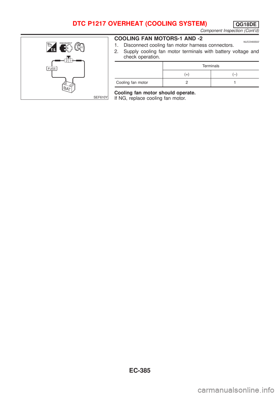
SEF610Y
COOLING FAN MOTORS-1 AND -2NLEC0493S021. Disconnect cooling fan motor harness connectors.
2. Supply cooling fan motor terminals with battery voltage and
check operation.
Terminals
(+) (þ)
Cooling fan motor 2 1
Cooling fan motor should operate.
If NG, replace cooling fan motor.
DTC P1217 OVERHEAT (COOLING SYSTEM)QG18DE
Component Inspection (Cont'd)
EC-385
Trending: exhaust manifold, brake, phone, refrigerant type, center console, brake sensor, fuel pump
