NISSAN ALMERA TINO 2001 Service Repair Manual
Manufacturer: NISSAN, Model Year: 2001, Model line: ALMERA TINO, Model: NISSAN ALMERA TINO 2001Pages: 3051, PDF Size: 46.38 MB
Page 871 of 3051
DescriptionNLEC1288SYSTEM DESCRIPTIONNLEC1288S01
Sensor Input Signal to ECMECM func-
tionActuator
Crankshaft position sensor (POS) Engine speed
EGR vol-
ume controlEGR volume control valve Camshaft position sensor (PHASE) Engine speed and cylinder number
Mass air flow sensor Amount of intake air
Engine coolant temperature sensor Engine coolant temperature
Ignition switch Start signal
Throttle position sensor Throttle position
Vehicle speed sensor Vehicle speed
Battery Battery voltage
Air conditioner switch Air conditioner operation
Power steering oil pressure switch Power steering load signal
Electrical load Electrical load signal
PNP switch Park/Neutral position signal
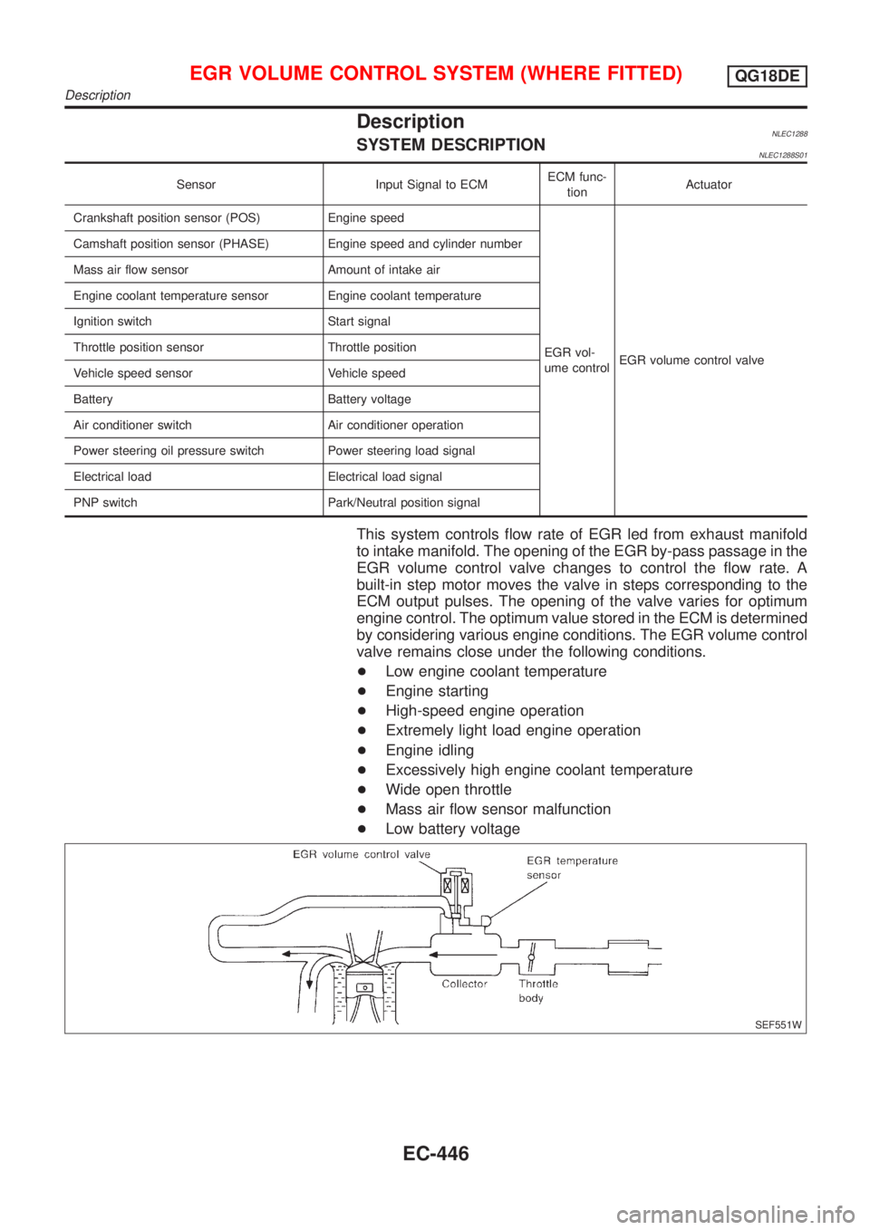
This system controls flow rate of EGR led from exhaust manifold
to intake manifold. The opening of the EGR by-pass passage in the
EGR volume control valve changes to control the flow rate. A
built-in step motor moves the valve in steps corresponding to the
ECM output pulses. The opening of the valve varies for optimum
engine control. The optimum value stored in the ECM is determined
by considering various engine conditions. The EGR volume control
valve remains close under the following conditions.
+Low engine coolant temperature
+Engine starting
+High-speed engine operation
+Extremely light load engine operation
+Engine idling
+Excessively high engine coolant temperature
+Wide open throttle
+Mass air flow sensor malfunction
+Low battery voltage
SEF551W
EGR VOLUME CONTROL SYSTEM (WHERE FITTED)QG18DE
Description
EC-446
Page 872 of 3051
SEF552W
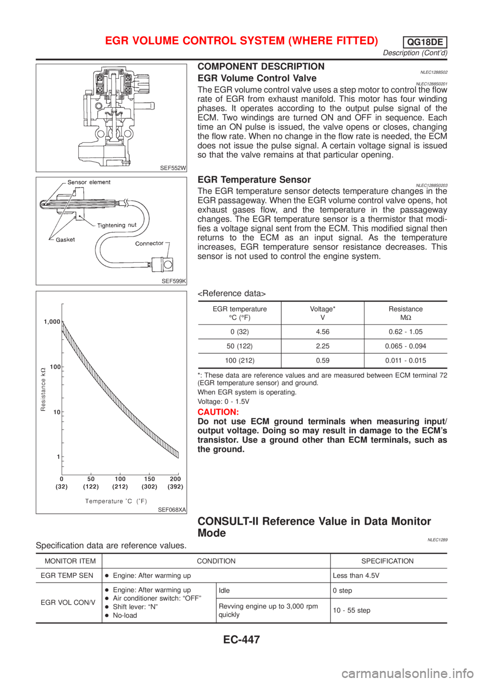
COMPONENT DESCRIPTIONNLEC1288S02EGR Volume Control ValveNLEC1288S0201The EGR volume control valve uses a step motor to control the flow
rate of EGR from exhaust manifold. This motor has four winding
phases. It operates according to the output pulse signal of the
ECM. Two windings are turned ON and OFF in sequence. Each
time an ON pulse is issued, the valve opens or closes, changing
the flow rate. When no change in the flow rate is needed, the ECM
does not issue the pulse signal. A certain voltage signal is issued
so that the valve remains at that particular opening.
SEF599K
EGR Temperature SensorNLEC1288S0203The EGR temperature sensor detects temperature changes in the
EGR passageway. When the EGR volume control valve opens, hot
exhaust gases flow, and the temperature in the passageway
changes. The EGR temperature sensor is a thermistor that modi-
fies a voltage signal sent from the ECM. This modified signal then
returns to the ECM as an input signal. As the temperature
increases, EGR temperature sensor resistance decreases. This
sensor is not used to control the engine system.
SEF068XA
EGR temperature
ÉC (ÉF)Voltage*
VResistance
MW
0 (32) 4.56 0.62 - 1.05
50 (122) 2.25 0.065 - 0.094
100 (212) 0.59 0.011 - 0.015
*: These data are reference values and are measured between ECM terminal 72
(EGR temperature sensor) and ground.
When EGR system is operating.
Voltage: 0 - 1.5V
CAUTION:
Do not use ECM ground terminals when measuring input/
output voltage. Doing so may result in damage to the ECM's
transistor. Use a ground other than ECM terminals, such as
the ground.
CONSULT-II Reference Value in Data Monitor
Mode
NLEC1289Specification data are reference values.
MONITOR ITEM CONDITION SPECIFICATION
EGR TEMP SEN+Engine: After warming up Less than 4.5V
EGR VOL CON/V+Engine: After warming up
+Air conditioner switch: ªOFFº
+Shift lever: ªNº
+No-loadIdle 0 step
Revving engine up to 3,000 rpm
quickly10 - 55 step
EGR VOLUME CONTROL SYSTEM (WHERE FITTED)QG18DE
Description (Cont'd)
EC-447
Page 873 of 3051
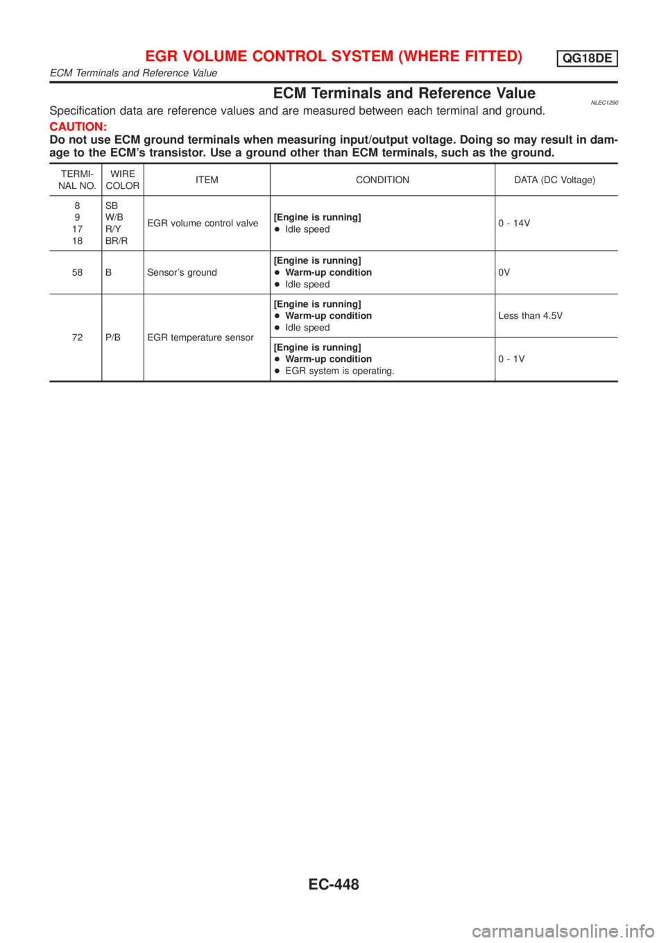
ECM Terminals and Reference ValueNLEC1290Specification data are reference values and are measured between each terminal and ground.
CAUTION:
Do not use ECM ground terminals when measuring input/output voltage. Doing so may result in dam-
age to the ECM's transistor. Use a ground other than ECM terminals, such as the ground.
TERMI-
NAL NO.WIRE
COLORITEM CONDITION DATA (DC Voltage)
8
9
17
18SB
W/B
R/Y
BR/REGR volume control valve[Engine is running]
+Idle speed0 - 14V
58 B Sensor's ground[Engine is running]
+Warm-up condition
+Idle speed0V
72 P/B EGR temperature sensor[Engine is running]
+Warm-up condition
+Idle speedLess than 4.5V
[Engine is running]
+Warm-up condition
+EGR system is operating.0-1V
EGR VOLUME CONTROL SYSTEM (WHERE FITTED)QG18DE
ECM Terminals and Reference Value
EC-448
Page 874 of 3051
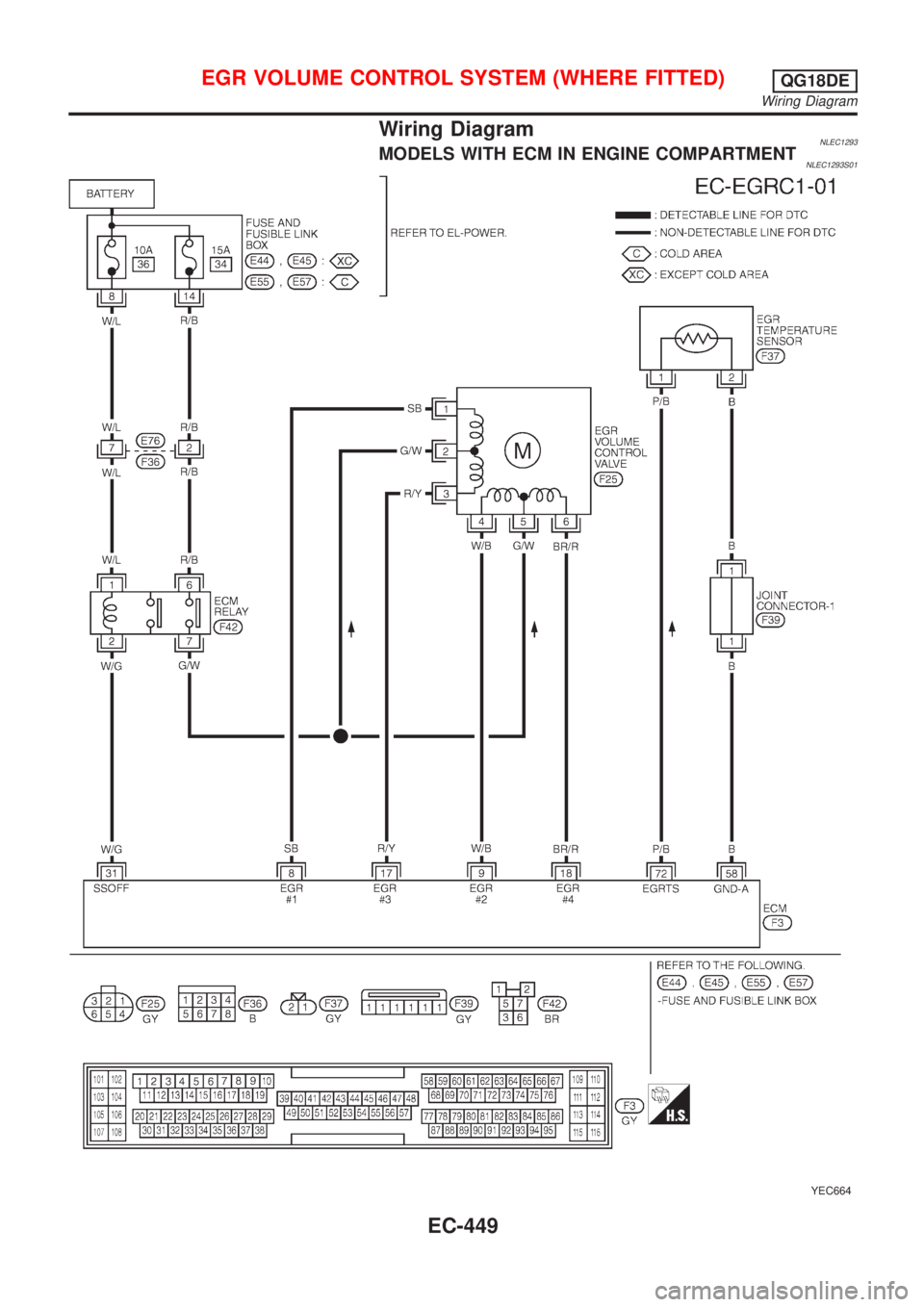
Wiring DiagramNLEC1293MODELS WITH ECM IN ENGINE COMPARTMENTNLEC1293S01
YEC664
EGR VOLUME CONTROL SYSTEM (WHERE FITTED)QG18DE
Wiring Diagram
EC-449
Page 875 of 3051
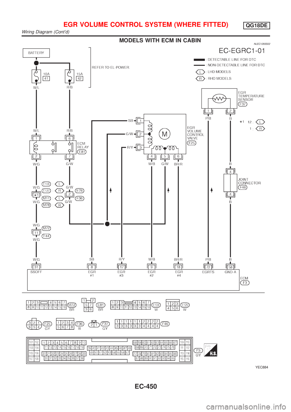
MODELS WITH ECM IN CABINNLEC1293S02
YEC884
EGR VOLUME CONTROL SYSTEM (WHERE FITTED)QG18DE
Wiring Diagram (Cont'd)
EC-450
Page 876 of 3051
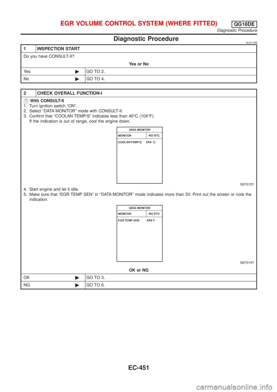
Diagnostic ProcedureNLEC1296
1 INSPECTION START
Do you have CONSULT-II?
YesorNo
Ye s©GO TO 2.
No©GO TO 4.
2 CHECK OVERALL FUNCTION-I
With CONSULT-II
1. Turn ignition switch ªONº.
2. Select ªDATA MONITORº mode with CONSULT-II.
3. Confirm that ªCOOLAN TEMP/Sº indicates less than 40ÉC (104ÉF).
If the indication is out of range, cool the engine down.
SEF013Y
4. Start engine and let it idle.
5. Make sure that ªEGR TEMP SENº in ªDATA MONITORº mode indicates more than 3V. Print out the screen or note the
indication.
SEF014Y
OK or NG
OK©GO TO 3.
NG©GO TO 6.
EGR VOLUME CONTROL SYSTEM (WHERE FITTED)QG18DE
Diagnostic Procedure
EC-451
Page 877 of 3051
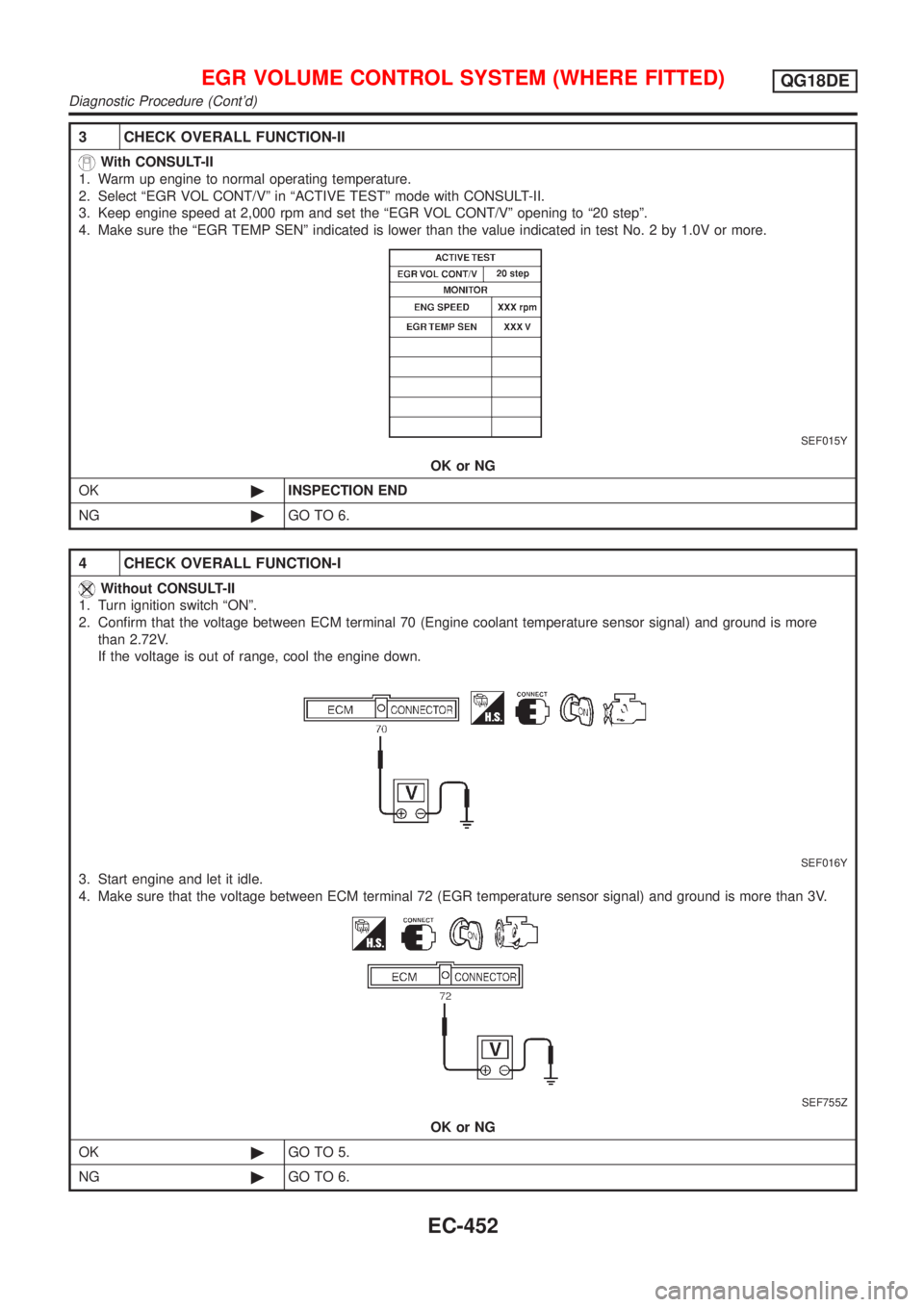
3 CHECK OVERALL FUNCTION-II
With CONSULT-II
1. Warm up engine to normal operating temperature.
2. Select ªEGR VOL CONT/Vº in ªACTIVE TESTº mode with CONSULT-II.
3. Keep engine speed at 2,000 rpm and set the ªEGR VOL CONT/Vº opening to ª20 stepº.
4. Make sure the ªEGR TEMP SENº indicated is lower than the value indicated in test No. 2 by 1.0V or more.
SEF015Y
OK or NG
OK©INSPECTION END
NG©GO TO 6.
4 CHECK OVERALL FUNCTION-I
Without CONSULT-II
1. Turn ignition switch ªONº.
2. Confirm that the voltage between ECM terminal 70 (Engine coolant temperature sensor signal) and ground is more
than 2.72V.
If the voltage is out of range, cool the engine down.
SEF016Y
3. Start engine and let it idle.
4. Make sure that the voltage between ECM terminal 72 (EGR temperature sensor signal) and ground is more than 3V.
SEF755Z
OK or NG
OK©GO TO 5.
NG©GO TO 6.
EGR VOLUME CONTROL SYSTEM (WHERE FITTED)QG18DE
Diagnostic Procedure (Cont'd)
EC-452
Page 878 of 3051
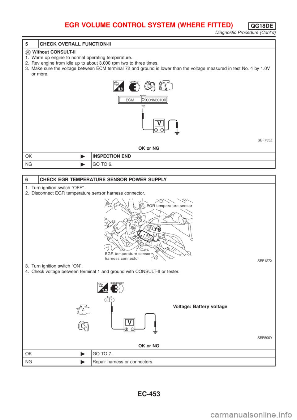
5 CHECK OVERALL FUNCTION-II
Without CONSULT-II
1. Warm up engine to normal operating temperature.
2. Rev engine from idle up to about 3,000 rpm two to three times.
3. Make sure the voltage between ECM terminal 72 and ground is lower than the voltage measured in test No. 4 by 1.0V
or more.
SEF755Z
OK or NG
OK©INSPECTION END
NG©GO TO 6.
6 CHECK EGR TEMPERATURE SENSOR POWER SUPPLY
1. Turn ignition switch ªOFFº.
2. Disconnect EGR temperature sensor harness connector.
SEF127X
3. Turn ignition switch ªONº.
4. Check voltage between terminal 1 and ground with CONSULT-II or tester.
SEF500Y
OK or NG
OK©GO TO 7.
NG©Repair harness or connectors.
EGR VOLUME CONTROL SYSTEM (WHERE FITTED)QG18DE
Diagnostic Procedure (Cont'd)
EC-453
Page 879 of 3051
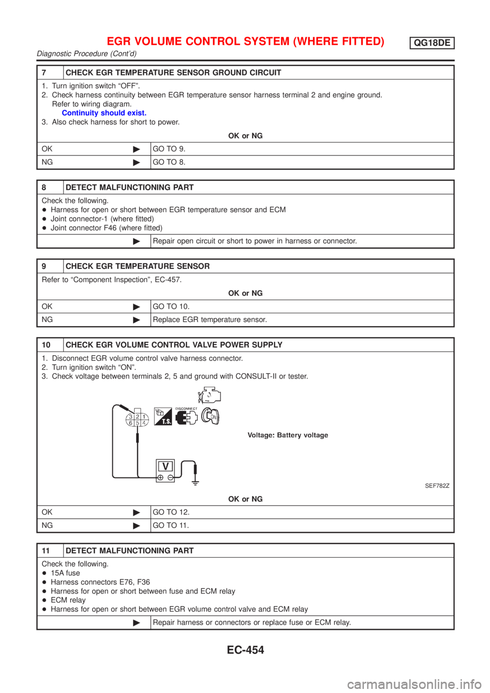
7 CHECK EGR TEMPERATURE SENSOR GROUND CIRCUIT
1. Turn ignition switch ªOFFº.
2. Check harness continuity between EGR temperature sensor harness terminal 2 and engine ground.
Refer to wiring diagram.
Continuity should exist.
3. Also check harness for short to power.
OK or NG
OK©GO TO 9.
NG©GO TO 8.
8 DETECT MALFUNCTIONING PART
Check the following.
+Harness for open or short between EGR temperature sensor and ECM
+Joint connector-1 (where fitted)
+Joint connector F46 (where fitted)
©Repair open circuit or short to power in harness or connector.
9 CHECK EGR TEMPERATURE SENSOR
Refer to ªComponent Inspectionº, EC-457.
OK or NG
OK©GO TO 10.
NG©Replace EGR temperature sensor.
10 CHECK EGR VOLUME CONTROL VALVE POWER SUPPLY
1. Disconnect EGR volume control valve harness connector.
2. Turn ignition switch ªONº.
3. Check voltage between terminals 2, 5 and ground with CONSULT-II or tester.
SEF782Z
OK or NG
OK©GO TO 12.
NG©GO TO 11.
11 DETECT MALFUNCTIONING PART
Check the following.
+15A fuse
+Harness connectors E76, F36
+Harness for open or short between fuse and ECM relay
+ECM relay
+Harness for open or short between EGR volume control valve and ECM relay
©Repair harness or connectors or replace fuse or ECM relay.
EGR VOLUME CONTROL SYSTEM (WHERE FITTED)QG18DE
Diagnostic Procedure (Cont'd)
EC-454
Page 880 of 3051
12 CHECK EGR VOLUME CONTROL VALVE OUTPUT SIGNAL CIRCUIT
1. Turn ignition switch ªOFFº.
2. Disconnect ECM harness connector.
3. Check harness continuity between
ECM terminal 8 and EGR volume control valve terminal 1,
ECM terminal 9 and EGR volume control valve terminal 4,
ECM terminal 17 and EGR volume control valve terminal 3,
ECM terminal 18 and EGR volume control valve terminal 6.
Refer to wiring diagram.
Continuity should exist.
4. Also check harness for short to ground and short to power.
OK or NG
OK©GO TO 13.
NG©Repair open circuit, short to ground or short to power in harness connectors.
13 CHECK EGR PASSAGE
Check EGR passage for clogging and cracks.
OK or NG
OK©GO TO 14.
NG©Repair or replace EGR passage.
14 CHECK EGR VOLUME CONTROL VALVE
Refer to ªCOMPONENT INSPECTIONº, EC-318.
OK or NG
OK©GO TO 15.
NG©Replace EGR volume control valve.
15 CHECK INTERMITTENT INCIDENT
Perform ªTROUBLE DIAGNOSIS FOR INTERMITTENT INCIDENTº, EC-145.
©INSPECTION END
EGR VOLUME CONTROL SYSTEM (WHERE FITTED)QG18DE
Diagnostic Procedure (Cont'd)
EC-455