NISSAN ALMERA TINO 2001 Service Repair Manual
Manufacturer: NISSAN, Model Year: 2001, Model line: ALMERA TINO, Model: NISSAN ALMERA TINO 2001Pages: 3051, PDF Size: 46.38 MB
Page 881 of 3051
SEF069X
SEF783Z
SEF015Y
SEF560W
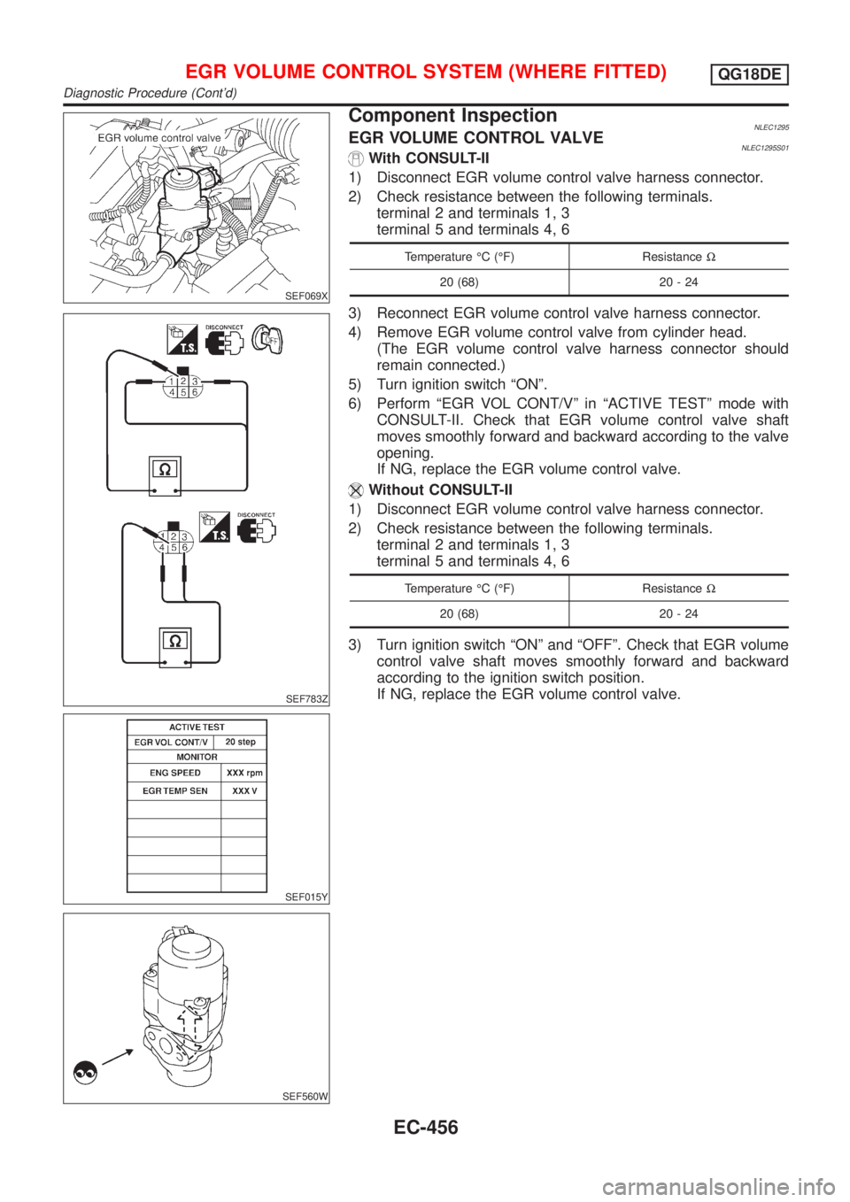
Component InspectionNLEC1295EGR VOLUME CONTROL VALVENLEC1295S01With CONSULT-II
1) Disconnect EGR volume control valve harness connector.
2) Check resistance between the following terminals.
terminal 2 and terminals 1, 3
terminal 5 and terminals 4, 6
Temperature ÉC (ÉF) ResistanceW
20 (68) 20 - 24
3) Reconnect EGR volume control valve harness connector.
4) Remove EGR volume control valve from cylinder head.
(The EGR volume control valve harness connector should
remain connected.)
5) Turn ignition switch ªONº.
6) Perform ªEGR VOL CONT/Vº in ªACTIVE TESTº mode with
CONSULT-II. Check that EGR volume control valve shaft
moves smoothly forward and backward according to the valve
opening.
If NG, replace the EGR volume control valve.
Without CONSULT-II
1) Disconnect EGR volume control valve harness connector.
2) Check resistance between the following terminals.
terminal 2 and terminals 1, 3
terminal 5 and terminals 4, 6
Temperature ÉC (ÉF) ResistanceW
20 (68) 20 - 24
3) Turn ignition switch ªONº and ªOFFº. Check that EGR volume
control valve shaft moves smoothly forward and backward
according to the ignition switch position.
If NG, replace the EGR volume control valve.
EGR VOLUME CONTROL SYSTEM (WHERE FITTED)QG18DE
Diagnostic Procedure (Cont'd)
EC-456
Page 882 of 3051
SEF611Y
SEF068XA
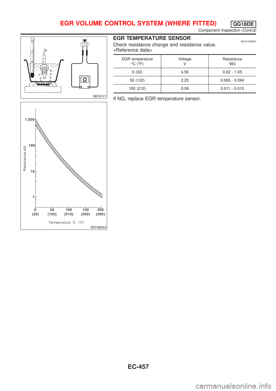
EGR TEMPERATURE SENSORNLEC1295S07Check resistance change and resistance value.
EGR temperature
ÉC (ÉF)Voltage
VResistance
MW
0 (32) 4.56 0.62 - 1.05
50 (122) 2.25 0.065 - 0.094
100 (212) 0.59 0.011 - 0.015
If NG, replace EGR temperature sensor.
EGR VOLUME CONTROL SYSTEM (WHERE FITTED)QG18DE
Component Inspection (Cont'd)
EC-457
Page 883 of 3051
DescriptionNLEC1297SYSTEM DESCRIPTIONNLEC1297S01
Sensor Input Signal to ECMECM func-
tionActuator
Crankshaft position sensor (POS) Engine speed
EVAP can-
ister purge
controlEVAP canister purge volume
control solenoid valve Camshaft position sensor (PHASE) Engine speed and cylinder number
Mass air flow sensor Amount of intake air
Engine coolant temperature sensor Engine coolant temperature
Battery Battery voltage
Ignition switch Start signal
Closed throttle position switch Closed throttle position
Throttle position sensor Throttle position
Heated oxygen sensor 1 (front)Density of oxygen in exhaust gas
(Mixture ratio feedback signal)
Vehicle speed sensor Vehicle speed
This system controls flow rate of fuel vapor from the EVAP canis-
ter. The opening of the vapor by-pass passage in the EVAP canis-
ter purge volume control solenoid valve changes to control the flow
rate. The EVAP canister purge volume control solenoid valve
repeats ON/OFF operation according to the signal sent from the
ECM. The opening of the valve varies for optimum engine control.
The optimum value stored in the ECM is determined by consider-
ing various engine conditions. When the engine is operating, the
flow rate of fuel vapor from the EVAP canister is regulated as the
air flow changes.
SEF337U
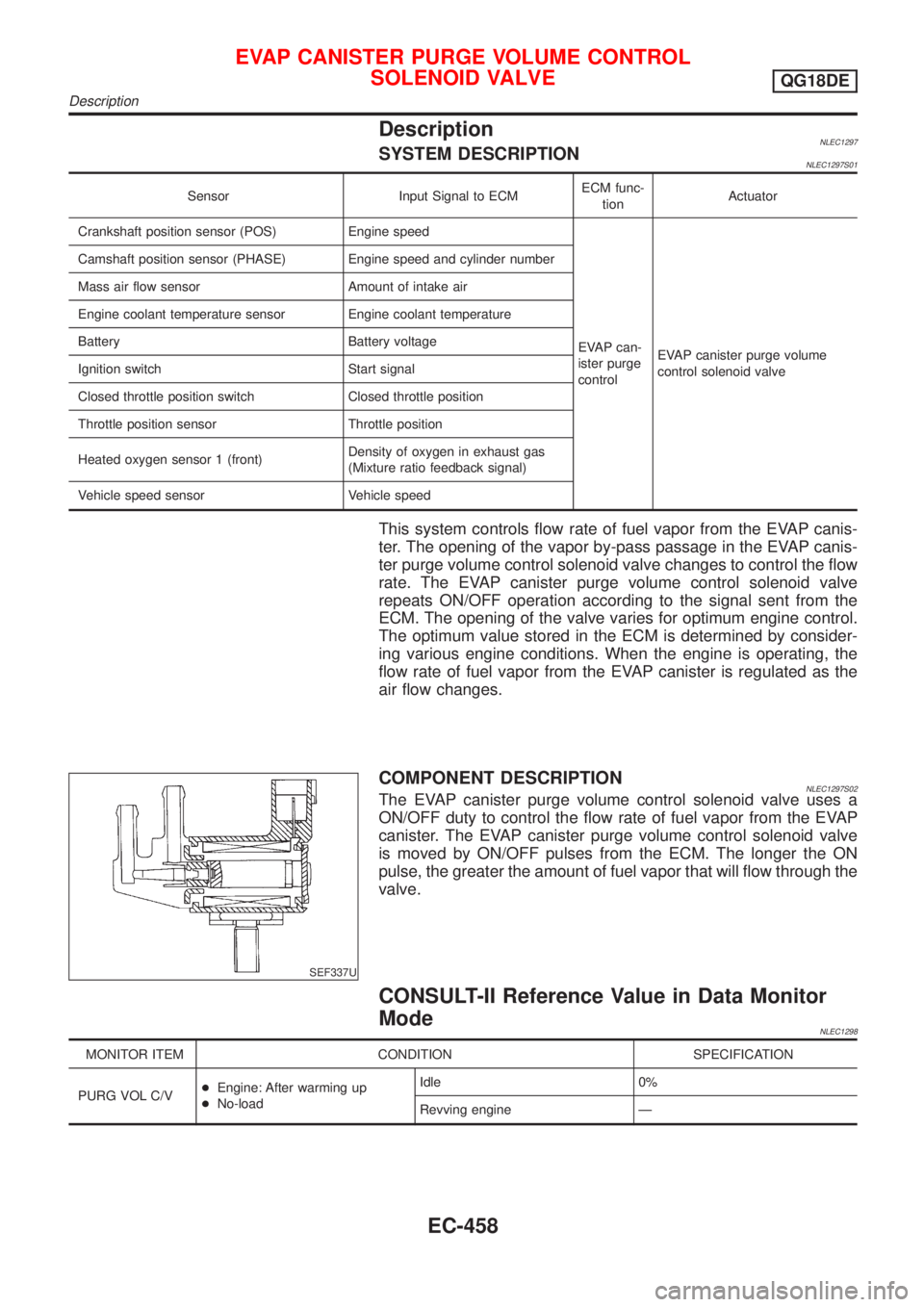
COMPONENT DESCRIPTIONNLEC1297S02The EVAP canister purge volume control solenoid valve uses a
ON/OFF duty to control the flow rate of fuel vapor from the EVAP
canister. The EVAP canister purge volume control solenoid valve
is moved by ON/OFF pulses from the ECM. The longer the ON
pulse, the greater the amount of fuel vapor that will flow through the
valve.
CONSULT-II Reference Value in Data Monitor
Mode
NLEC1298
MONITOR ITEM CONDITION SPECIFICATION
PURG VOL C/V+Engine: After warming up
+No-loadIdle 0%
Revving engine Ð
EVAP CANISTER PURGE VOLUME CONTROL
SOLENOID VALVE
QG18DE
Description
EC-458
Page 884 of 3051
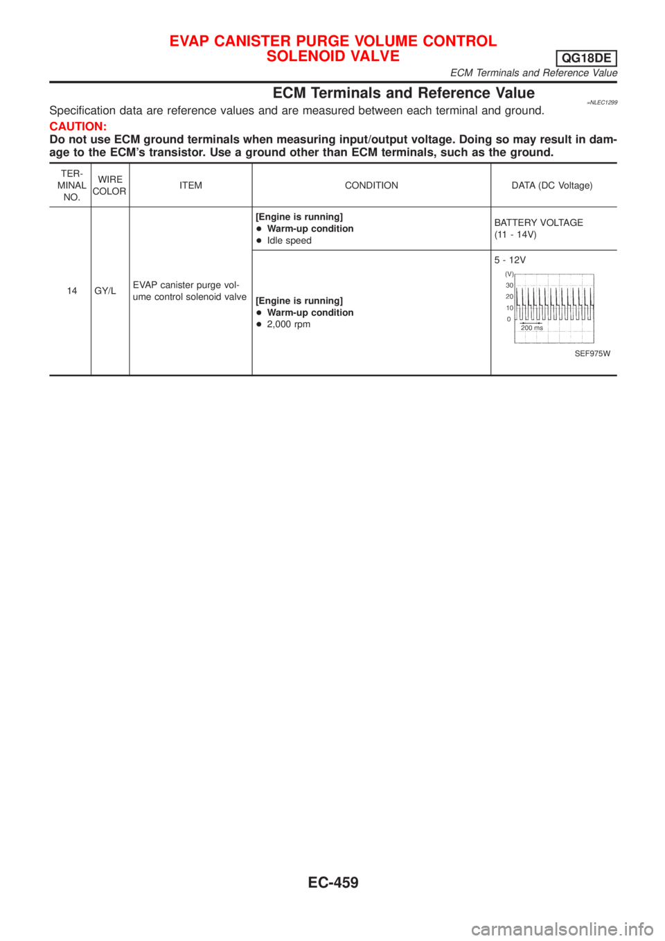
ECM Terminals and Reference Value=NLEC1299Specification data are reference values and are measured between each terminal and ground.
CAUTION:
Do not use ECM ground terminals when measuring input/output voltage. Doing so may result in dam-
age to the ECM's transistor. Use a ground other than ECM terminals, such as the ground.
TER-
MINAL
NO.WIRE
COLORITEM CONDITION DATA (DC Voltage)
14 GY/LEVAP canister purge vol-
ume control solenoid valve[Engine is running]
+Warm-up condition
+Idle speedBATTERY VOLTAGE
(11 - 14V)
[Engine is running]
+Warm-up condition
+2,000 rpm5 - 12V
SEF975W
EVAP CANISTER PURGE VOLUME CONTROL
SOLENOID VALVE
QG18DE
ECM Terminals and Reference Value
EC-459
Page 885 of 3051
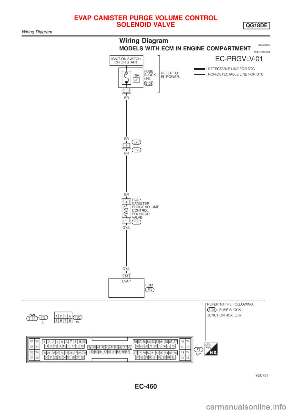
Wiring DiagramNLEC1302MODELS WITH ECM IN ENGINE COMPARTMENTNLEC1302S01
YEC751
EVAP CANISTER PURGE VOLUME CONTROL
SOLENOID VALVE
QG18DE
Wiring Diagram
EC-460
Page 886 of 3051
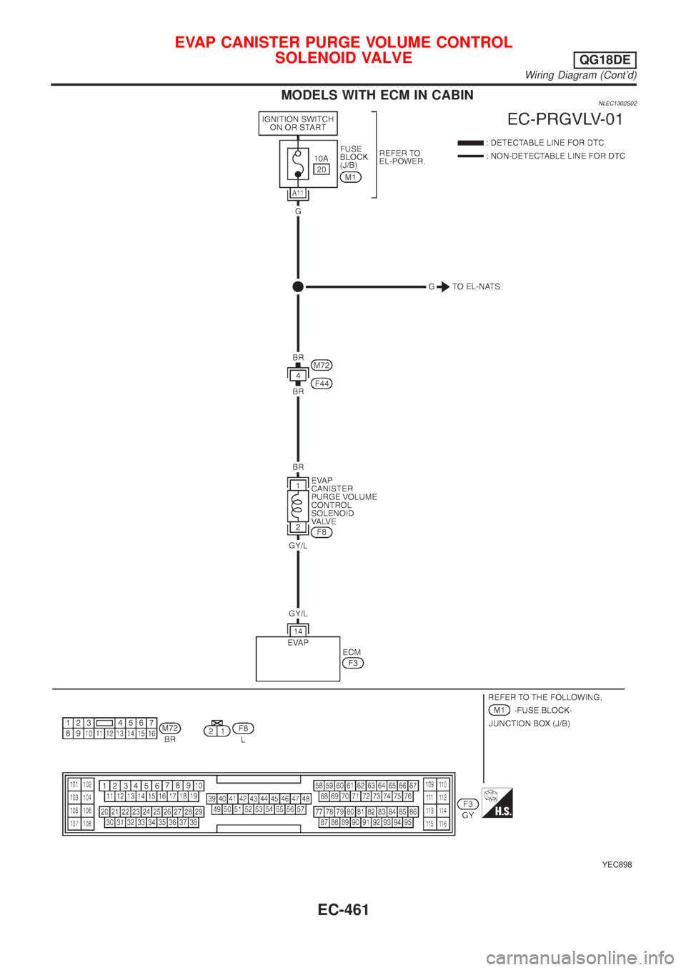
MODELS WITH ECM IN CABINNLEC1302S02
YEC898
EVAP CANISTER PURGE VOLUME CONTROL
SOLENOID VALVE
QG18DE
Wiring Diagram (Cont'd)
EC-461
Page 887 of 3051
Diagnostic ProcedureNLEC1303
1 INSPECTION START
Do you have CONSULT-II?
YesorNo
Ye s©GO TO 2.
No©GO TO 3.
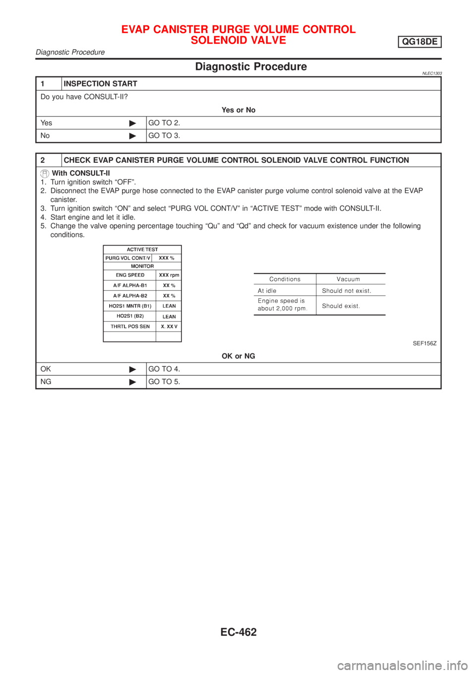
2 CHECK EVAP CANISTER PURGE VOLUME CONTROL SOLENOID VALVE CONTROL FUNCTION
With CONSULT-II
1. Turn ignition switch ªOFFº.
2. Disconnect the EVAP purge hose connected to the EVAP canister purge volume control solenoid valve at the EVAP
canister.
3. Turn ignition switch ªONº and select ªPURG VOL CONT/Vº in ªACTIVE TESTº mode with CONSULT-II.
4. Start engine and let it idle.
5. Change the valve opening percentage touching ªQuº and ªQdº and check for vacuum existence under the following
conditions.
SEF156Z
OK or NG
OK©GO TO 4.
NG©GO TO 5.
EVAP CANISTER PURGE VOLUME CONTROL
SOLENOID VALVE
QG18DE
Diagnostic Procedure
EC-462
Page 888 of 3051
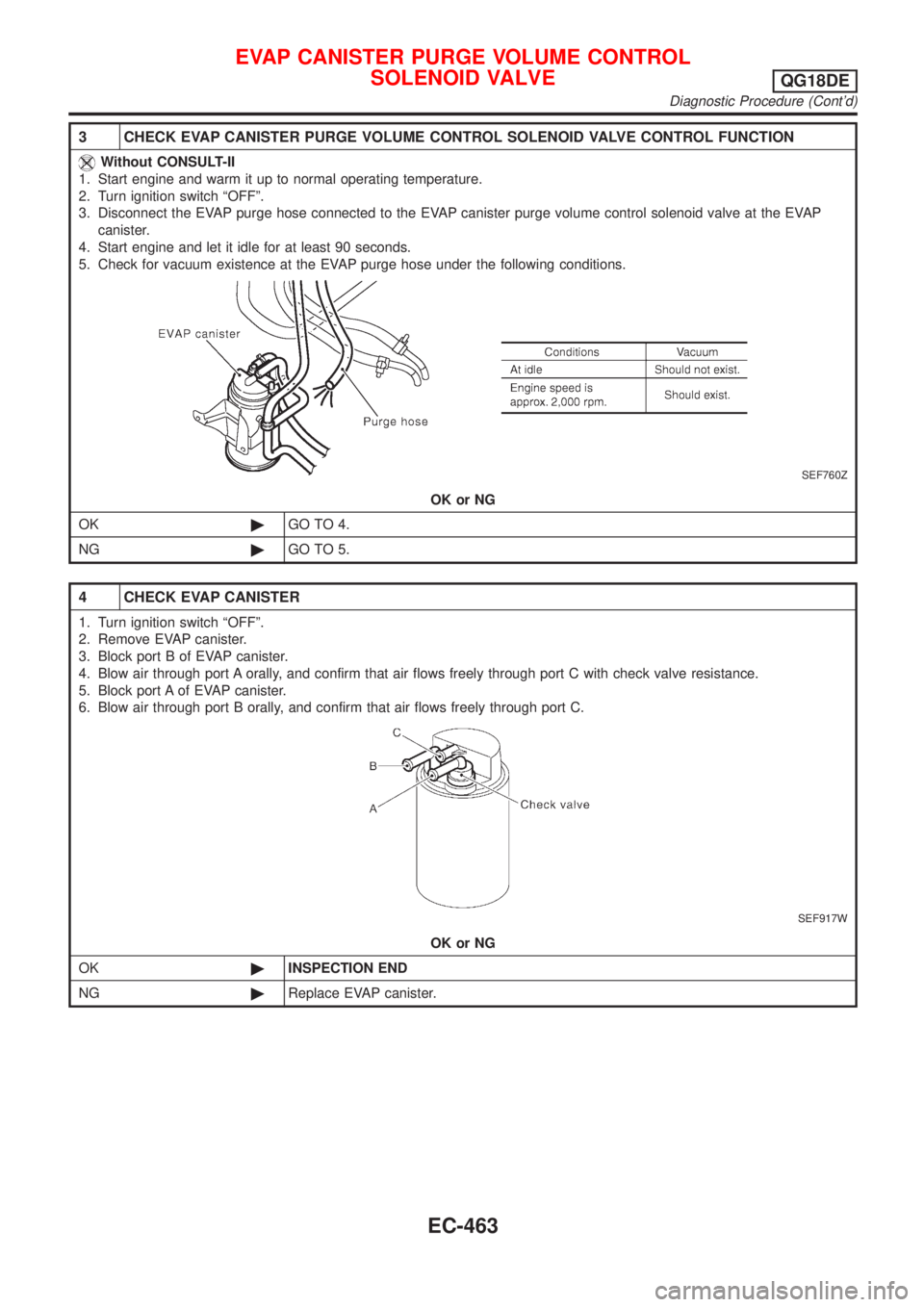
3 CHECK EVAP CANISTER PURGE VOLUME CONTROL SOLENOID VALVE CONTROL FUNCTION
Without CONSULT-II
1. Start engine and warm it up to normal operating temperature.
2. Turn ignition switch ªOFFº.
3. Disconnect the EVAP purge hose connected to the EVAP canister purge volume control solenoid valve at the EVAP
canister.
4. Start engine and let it idle for at least 90 seconds.
5. Check for vacuum existence at the EVAP purge hose under the following conditions.
SEF760Z
OK or NG
OK©GO TO 4.
NG©GO TO 5.
4 CHECK EVAP CANISTER
1. Turn ignition switch ªOFFº.
2. Remove EVAP canister.
3. Block port B of EVAP canister.
4. Blow air through port A orally, and confirm that air flows freely through port C with check valve resistance.
5. Block port A of EVAP canister.
6. Blow air through port B orally, and confirm that air flows freely through port C.
SEF917W
OK or NG
OK©INSPECTION END
NG©Replace EVAP canister.
EVAP CANISTER PURGE VOLUME CONTROL
SOLENOID VALVE
QG18DE
Diagnostic Procedure (Cont'd)
EC-463
Page 889 of 3051
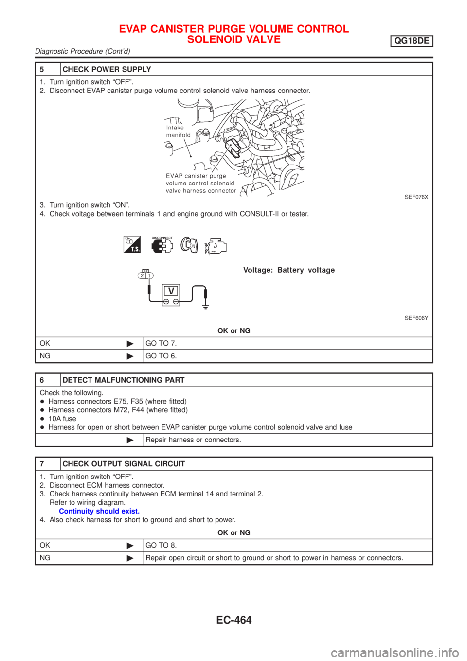
5 CHECK POWER SUPPLY
1. Turn ignition switch ªOFFº.
2. Disconnect EVAP canister purge volume control solenoid valve harness connector.
SEF076X
3. Turn ignition switch ªONº.
4. Check voltage between terminals 1 and engine ground with CONSULT-II or tester.
SEF606Y
OK or NG
OK©GO TO 7.
NG©GO TO 6.
6 DETECT MALFUNCTIONING PART
Check the following.
+Harness connectors E75, F35 (where fitted)
+Harness connectors M72, F44 (where fitted)
+10A fuse
+Harness for open or short between EVAP canister purge volume control solenoid valve and fuse
©Repair harness or connectors.
7 CHECK OUTPUT SIGNAL CIRCUIT
1. Turn ignition switch ªOFFº.
2. Disconnect ECM harness connector.
3. Check harness continuity between ECM terminal 14 and terminal 2.
Refer to wiring diagram.
Continuity should exist.
4. Also check harness for short to ground and short to power.
OK or NG
OK©GO TO 8.
NG©Repair open circuit or short to ground or short to power in harness or connectors.
EVAP CANISTER PURGE VOLUME CONTROL
SOLENOID VALVE
QG18DE
Diagnostic Procedure (Cont'd)
EC-464
Page 890 of 3051
8 CHECK EVAP CANISTER PURGE VOLUME CONTROL SOLENOID VALVE
Refer to ªComponent Inspectionº EC-465.
OK or NG
OK©GO TO 9.
NG©Replace EVAP canister purge volume control solenoid valve.
9 CHECK INTERMITTENT INCIDENT
Perform ªTROUBLE DIAGNOSIS FOR INTERMITTENT INCIDENTº, EC-145.
©INSPECTION END
SEF677Y
SEF661U
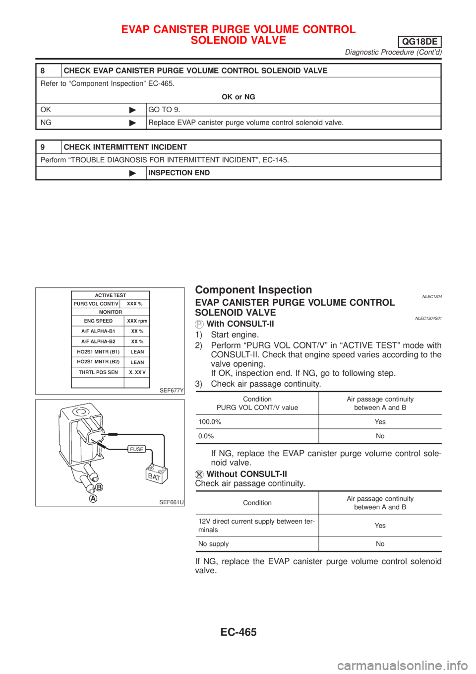
Component InspectionNLEC1304EVAP CANISTER PURGE VOLUME CONTROL
SOLENOID VALVE
NLEC1304S01With CONSULT-II
1) Start engine.
2) Perform ªPURG VOL CONT/Vº in ªACTIVE TESTº mode with
CONSULT-II. Check that engine speed varies according to the
valve opening.
If OK, inspection end. If NG, go to following step.
3) Check air passage continuity.
Condition
PURG VOL CONT/V valueAir passage continuity
between A and B
100.0% Yes
0.0% No
If NG, replace the EVAP canister purge volume control sole-
noid valve.
Without CONSULT-II
Check air passage continuity.
ConditionAir passage continuity
between A and B
12V direct current supply between ter-
minalsYe s
No supply No
If NG, replace the EVAP canister purge volume control solenoid
valve.
EVAP CANISTER PURGE VOLUME CONTROL
SOLENOID VALVE
QG18DE
Diagnostic Procedure (Cont'd)
EC-465