NISSAN ALMERA TINO 2001 Service Repair Manual
ALMERA TINO 2001
NISSAN
NISSAN
https://www.carmanualsonline.info/img/5/57352/w960_57352-0.png
NISSAN ALMERA TINO 2001 Service Repair Manual
Trending: service reset, bulb, sunroof, mileage, check transmission fluid, airbag off, coolant capacity
Page 861 of 3051
Diagnostic ProcedureNLEC1246
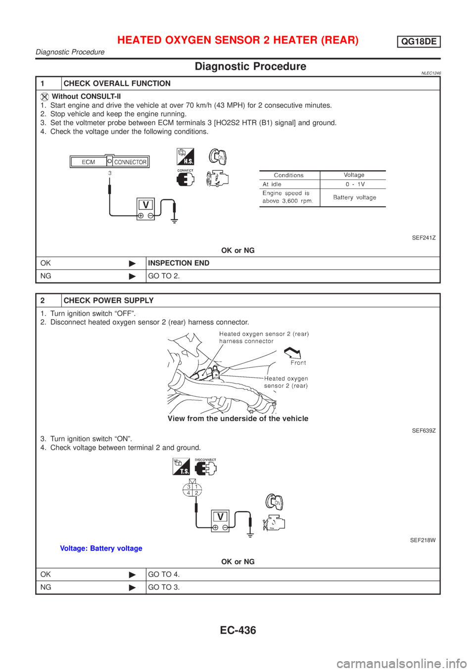
1 CHECK OVERALL FUNCTION
Without CONSULT-II
1. Start engine and drive the vehicle at over 70 km/h (43 MPH) for 2 consecutive minutes.
2. Stop vehicle and keep the engine running.
3. Set the voltmeter probe between ECM terminals 3 [HO2S2 HTR (B1) signal] and ground.
4. Check the voltage under the following conditions.
SEF241Z
OK or NG
OK©INSPECTION END
NG©GO TO 2.
2 CHECK POWER SUPPLY
1. Turn ignition switch ªOFFº.
2. Disconnect heated oxygen sensor 2 (rear) harness connector.
SEF639Z
3. Turn ignition switch ªONº.
4. Check voltage between terminal 2 and ground.
SEF218W
Voltage: Battery voltage
OK or NG
OK©GO TO 4.
NG©GO TO 3.
HEATED OXYGEN SENSOR 2 HEATER (REAR)QG18DE
Diagnostic Procedure
EC-436
Page 862 of 3051
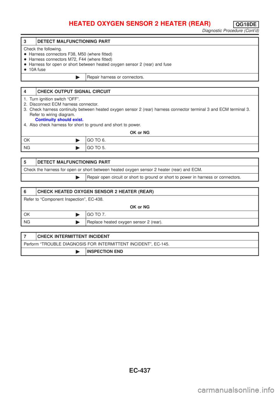
3 DETECT MALFUNCTIONING PART
Check the following.
+Harness connectors F38, M50 (where fitted)
+Harness connectors M72, F44 (where fitted)
+Harness for open or short between heated oxygen sensor 2 (rear) and fuse
+10A fuse
©Repair harness or connectors.
4 CHECK OUTPUT SIGNAL CIRCUIT
1. Turn ignition switch ªOFFº.
2. Disconnect ECM harness connector.
3. Check harness continuity between heated oxygen sensor 2 (rear) harness connector terminal 3 and ECM terminal 3.
Refer to wiring diagram.
Continuity should exist.
4. Also check harness for short to ground and short to power.
OK or NG
OK©GO TO 6.
NG©GO TO 5.
5 DETECT MALFUNCTIONING PART
Check the harness for open or short between heated oxygen sensor 2 heater (rear) and ECM.
©Repair open circuit or short to ground or short to power in harness or connectors.
6 CHECK HEATED OXYGEN SENSOR 2 HEATER (REAR)
Refer to ªComponent Inspectionº, EC-438.
OK or NG
OK©GO TO 7.
NG©Replace heated oxygen sensor 2 (rear).
7 CHECK INTERMITTENT INCIDENT
Perform ªTROUBLE DIAGNOSIS FOR INTERMITTENT INCIDENTº, EC-145.
©INSPECTION END
HEATED OXYGEN SENSOR 2 HEATER (REAR)QG18DE
Diagnostic Procedure (Cont'd)
EC-437
Page 863 of 3051
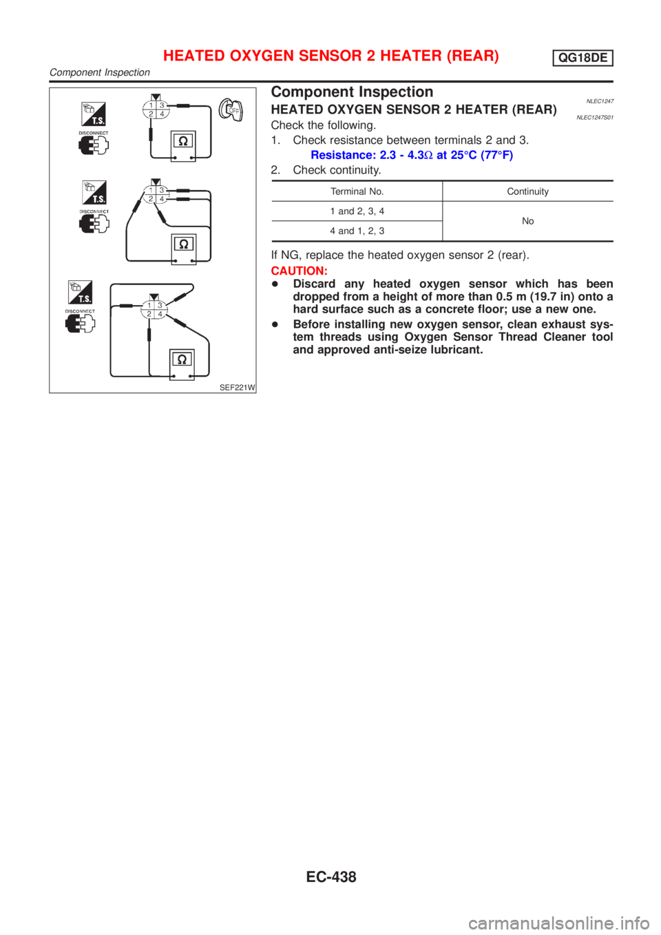
SEF221W
Component InspectionNLEC1247HEATED OXYGEN SENSOR 2 HEATER (REAR)NLEC1247S01Check the following.
1. Check resistance between terminals 2 and 3.
Resistance: 2.3 - 4.3Wat 25ÉC (77ÉF)
2. Check continuity.
Terminal No. Continuity
1 and 2, 3, 4
No
4 and 1, 2, 3
If NG, replace the heated oxygen sensor 2 (rear).
CAUTION:
+Discard any heated oxygen sensor which has been
dropped from a height of more than 0.5 m (19.7 in) onto a
hard surface such as a concrete floor; use a new one.
+Before installing new oxygen sensor, clean exhaust sys-
tem threads using Oxygen Sensor Thread Cleaner tool
and approved anti-seize lubricant.
HEATED OXYGEN SENSOR 2 HEATER (REAR)QG18DE
Component Inspection
EC-438
Page 864 of 3051
SEF058X
JEF835Z
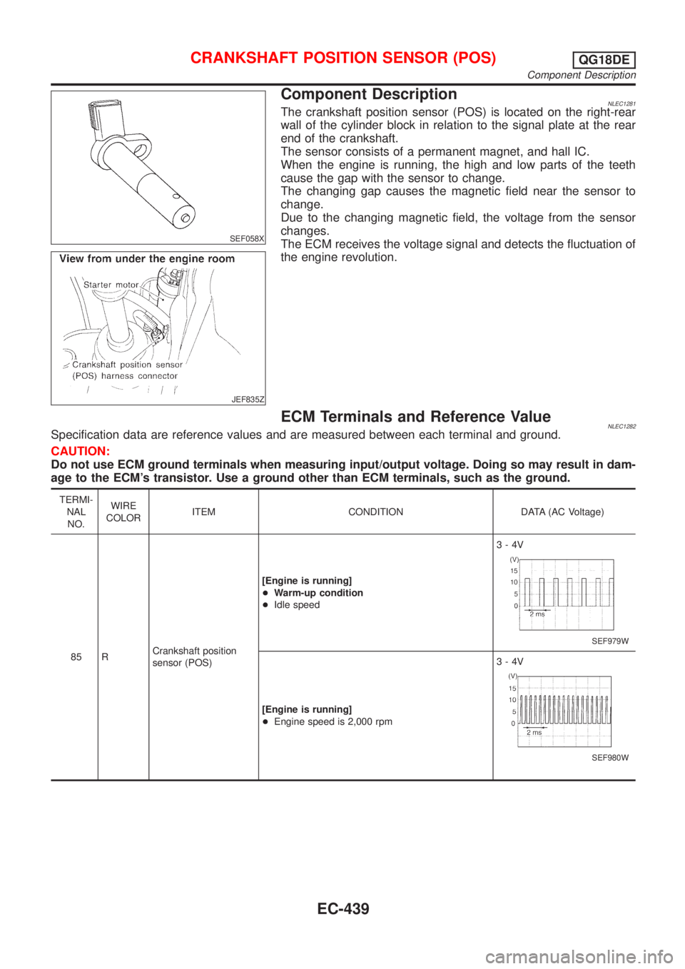
Component DescriptionNLEC1281The crankshaft position sensor (POS) is located on the right-rear
wall of the cylinder block in relation to the signal plate at the rear
end of the crankshaft.
The sensor consists of a permanent magnet, and hall IC.
When the engine is running, the high and low parts of the teeth
cause the gap with the sensor to change.
The changing gap causes the magnetic field near the sensor to
change.
Due to the changing magnetic field, the voltage from the sensor
changes.
The ECM receives the voltage signal and detects the fluctuation of
the engine revolution.
ECM Terminals and Reference ValueNLEC1282Specification data are reference values and are measured between each terminal and ground.
CAUTION:
Do not use ECM ground terminals when measuring input/output voltage. Doing so may result in dam-
age to the ECM's transistor. Use a ground other than ECM terminals, such as the ground.
TERMI-
NAL
NO.WIRE
COLORITEM CONDITION DATA (AC Voltage)
85 RCrankshaft position
sensor (POS)[Engine is running]
+Warm-up condition
+Idle speed3-4V
SEF979W
[Engine is running]
+Engine speed is 2,000 rpm3-4V
SEF980W
CRANKSHAFT POSITION SENSOR (POS)QG18DE
Component Description
EC-439
Page 865 of 3051
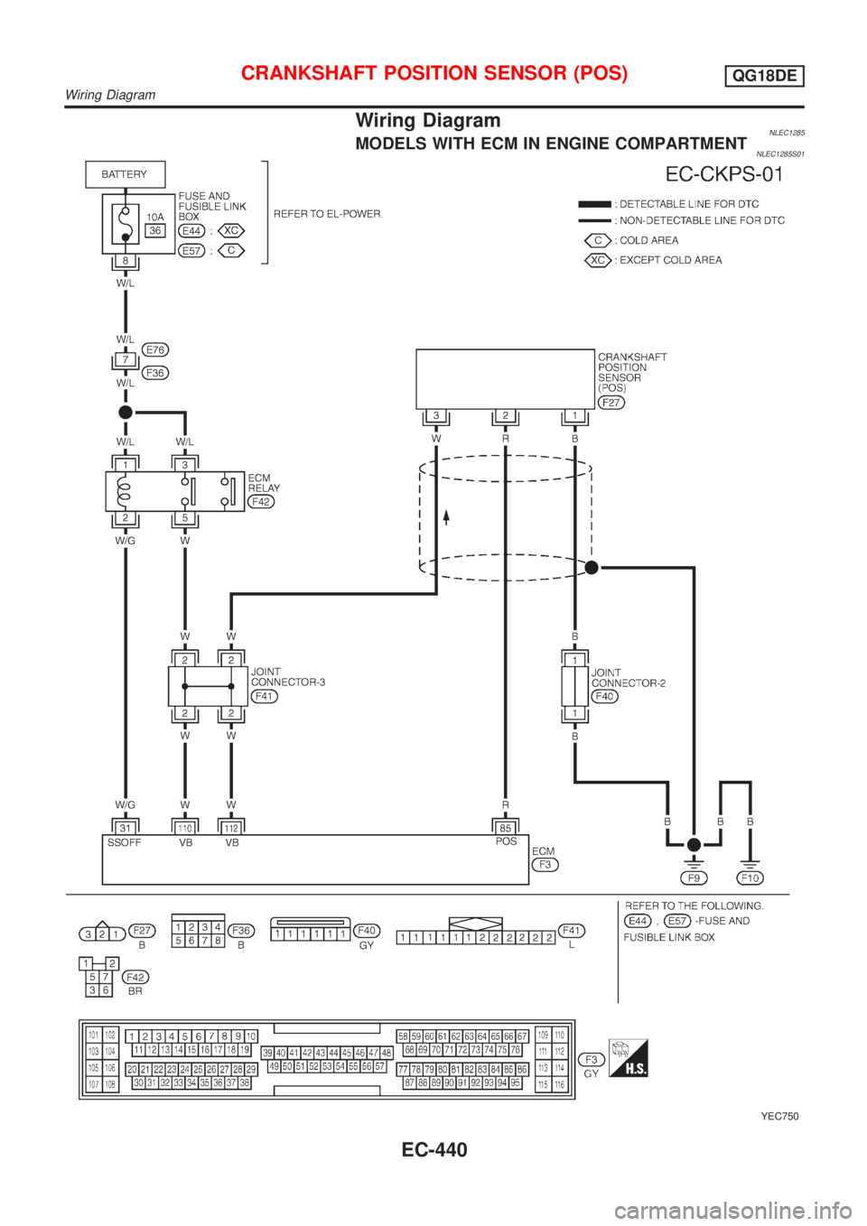
Wiring DiagramNLEC1285MODELS WITH ECM IN ENGINE COMPARTMENTNLEC1285S01
YEC750
CRANKSHAFT POSITION SENSOR (POS)QG18DE
Wiring Diagram
EC-440
Page 866 of 3051
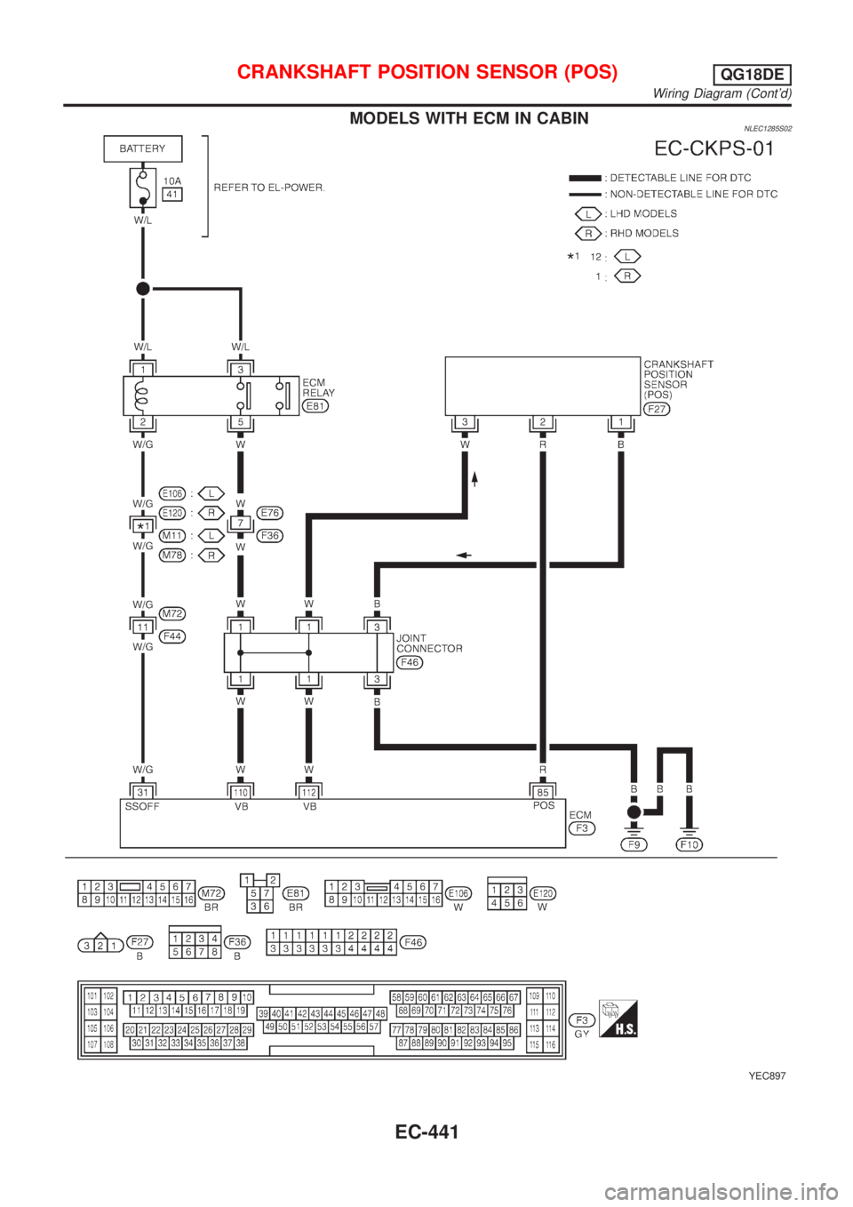
MODELS WITH ECM IN CABINNLEC1285S02
YEC897
CRANKSHAFT POSITION SENSOR (POS)QG18DE
Wiring Diagram (Cont'd)
EC-441
Page 867 of 3051
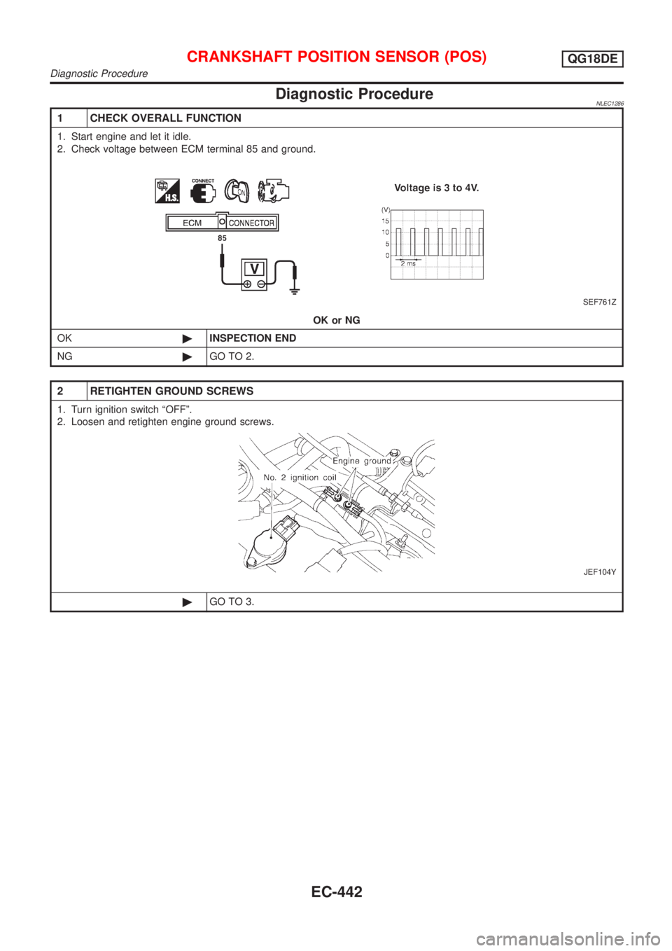
Diagnostic ProcedureNLEC1286
1 CHECK OVERALL FUNCTION
1. Start engine and let it idle.
2. Check voltage between ECM terminal 85 and ground.
SEF761Z
OK or NG
OK©INSPECTION END
NG©GO TO 2.
2 RETIGHTEN GROUND SCREWS
1. Turn ignition switch ªOFFº.
2. Loosen and retighten engine ground screws.
JEF104Y
©GO TO 3.
CRANKSHAFT POSITION SENSOR (POS)QG18DE
Diagnostic Procedure
EC-442
Page 868 of 3051
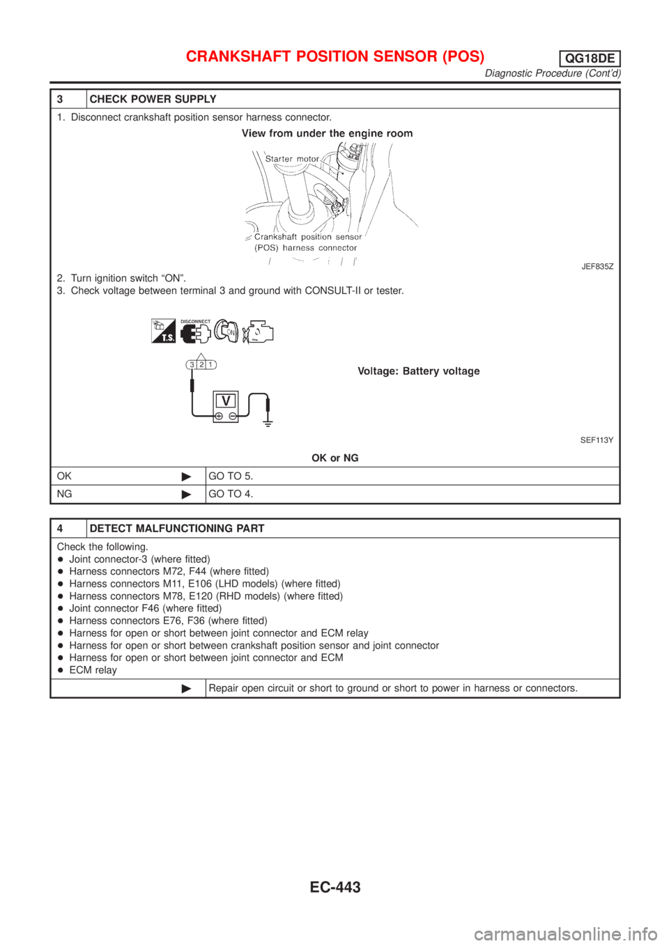
3 CHECK POWER SUPPLY
1. Disconnect crankshaft position sensor harness connector.
JEF835Z
2. Turn ignition switch ªONº.
3. Check voltage between terminal 3 and ground with CONSULT-II or tester.
SEF113Y
OK or NG
OK©GO TO 5.
NG©GO TO 4.
4 DETECT MALFUNCTIONING PART
Check the following.
+Joint connector-3 (where fitted)
+Harness connectors M72, F44 (where fitted)
+Harness connectors M11, E106 (LHD models) (where fitted)
+Harness connectors M78, E120 (RHD models) (where fitted)
+Joint connector F46 (where fitted)
+Harness connectors E76, F36 (where fitted)
+Harness for open or short between joint connector and ECM relay
+Harness for open or short between crankshaft position sensor and joint connector
+Harness for open or short between joint connector and ECM
+ECM relay
©Repair open circuit or short to ground or short to power in harness or connectors.
CRANKSHAFT POSITION SENSOR (POS)QG18DE
Diagnostic Procedure (Cont'd)
EC-443
Page 869 of 3051
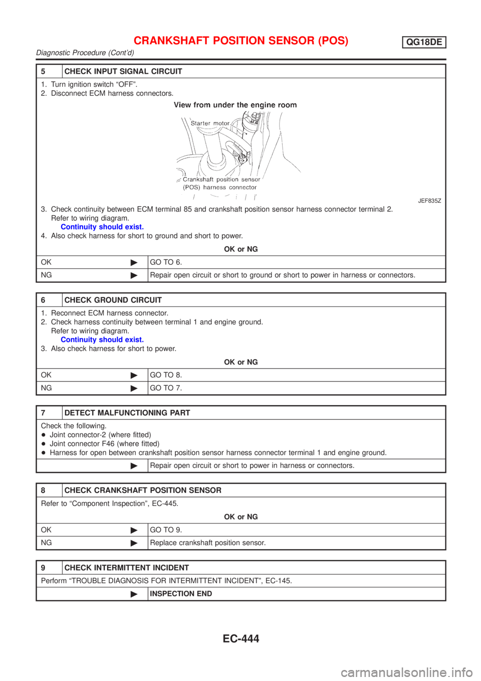
5 CHECK INPUT SIGNAL CIRCUIT
1. Turn ignition switch ªOFFº.
2. Disconnect ECM harness connectors.
JEF835Z
3. Check continuity between ECM terminal 85 and crankshaft position sensor harness connector terminal 2.
Refer to wiring diagram.
Continuity should exist.
4. Also check harness for short to ground and short to power.
OK or NG
OK©GO TO 6.
NG©Repair open circuit or short to ground or short to power in harness or connectors.
6 CHECK GROUND CIRCUIT
1. Reconnect ECM harness connector.
2. Check harness continuity between terminal 1 and engine ground.
Refer to wiring diagram.
Continuity should exist.
3. Also check harness for short to power.
OK or NG
OK©GO TO 8.
NG©GO TO 7.
7 DETECT MALFUNCTIONING PART
Check the following.
+Joint connector-2 (where fitted)
+Joint connector F46 (where fitted)
+Harness for open between crankshaft position sensor harness connector terminal 1 and engine ground.
©Repair open circuit or short to power in harness or connectors.
8 CHECK CRANKSHAFT POSITION SENSOR
Refer to ªComponent Inspectionº, EC-445.
OK or NG
OK©GO TO 9.
NG©Replace crankshaft position sensor.
9 CHECK INTERMITTENT INCIDENT
Perform ªTROUBLE DIAGNOSIS FOR INTERMITTENT INCIDENTº, EC-145.
©INSPECTION END
CRANKSHAFT POSITION SENSOR (POS)QG18DE
Diagnostic Procedure (Cont'd)
EC-444
Page 870 of 3051
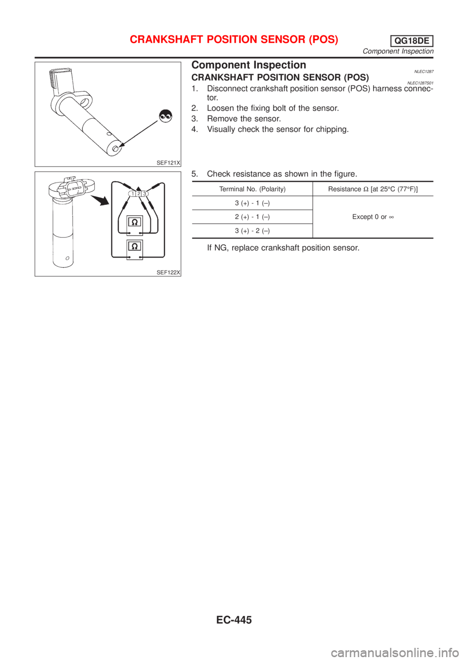
SEF121X
Component InspectionNLEC1287CRANKSHAFT POSITION SENSOR (POS)NLEC1287S011. Disconnect crankshaft position sensor (POS) harness connec-
tor.
2. Loosen the fixing bolt of the sensor.
3. Remove the sensor.
4. Visually check the sensor for chipping.
SEF122X
5. Check resistance as shown in the figure.
Terminal No. (Polarity) ResistanceW[at 25ÉC (77ÉF)]
3 (+) - 1 (±)
Except 0 or¥ 2 (+) - 1 (±)
3 (+) - 2 (±)
If NG, replace crankshaft position sensor.
CRANKSHAFT POSITION SENSOR (POS)QG18DE
Component Inspection
EC-445
Trending: inflation pressure, wheel, steering wheel, instrument, brakes, engine oil capacity, brake pads
