NISSAN ALMERA TINO 2001 Service Repair Manual
Manufacturer: NISSAN, Model Year: 2001, Model line: ALMERA TINO, Model: NISSAN ALMERA TINO 2001Pages: 3051, PDF Size: 46.38 MB
Page 911 of 3051
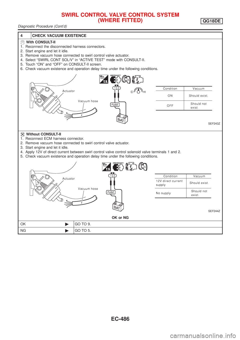
4 CHECK VACUUM EXISTENCE
With CONSULT-II
1. Reconnect the disconnected harness connectors.
2. Start engine and let it idle.
3. Remove vacuum hose connected to swirl control valve actuator.
4. Select ÂȘSWIRL CONT SOL/VÂș in ÂȘACTIVE TESTÂș mode with CONSULT-II.
5. Touch ÂȘONÂș and ÂȘOFFÂș on CONSULT-II screen.
6. Check vacuum existence and operation delay time under the following conditions.
SEF243Z
Without CONSULT-II
1. Reconnect ECM harness connector.
2. Remove vacuum hose connected to swirl control valve actuator.
3. Start engine and let it idle.
4. Apply 12V of direct current between swirl control valve control solenoid valve terminals 1 and 2.
5. Check vacuum existence and operation delay time under the following conditions.
SEF244Z
OK or NG
OK©GO TO 9.
NG©GO TO 5.
SWIRL CONTROL VALVE CONTROL SYSTEM
(WHERE FITTED)
QG18DE
Diagnostic Procedure (Cont'd)
EC-486
Page 912 of 3051
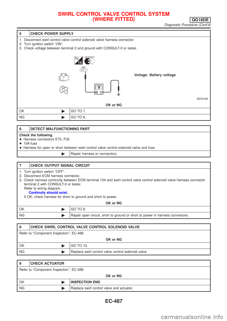
5 CHECK POWER SUPPLY
1. Disconnect swirl control valve control solenoid valve harness connector.
2. Turn ignition switch ÂȘONÂș.
3. Check voltage between terminal 2 and ground with CONSULT-II or tester.
SEF619X
OK or NG
OK©GO TO 7.
NG©GO TO 6.
6 DETECT MALFUNCTIONING PART
Check the following.
+Harness connectors E75, F35
+10A fuse
+Harness for open or short between swirl control valve control solenoid valve and fuse
©Repair harness or connectors.
7 CHECK OUTPUT SIGNAL CIRCUIT
1. Turn ignition switch ÂȘOFFÂș.
2. Disconnect ECM harness connector.
3. Check harness continuity between ECM terminal 104 and swirl control valve control solenoid valve harness connector
terminal 2 with CONSULT-II or tester.
Refer to wiring diagram.
Continuity should exist.
If OK, check harness for short to ground and short to power.
OK or NG
OK©GO TO 8.
NG©Repair open circuit, short to ground or short to power in harness connectors.
8 CHECK SWIRL CONTROL VALVE CONTROL SOLENOID VALVE
Refer to ÂȘComponent InspectionÂș, EC-488.
OK or NG
OK©GO TO 10.
NG©Replace swirl control valve control solenoid valve.
9 CHECK ACTUATOR
Refer to ÂȘComponent InspectionÂș, EC-488.
OK or NG
OK©INSPECTION END
NG©Replace swirl control valve and actuator.
SWIRL CONTROL VALVE CONTROL SYSTEM
(WHERE FITTED)
QG18DE
Diagnostic Procedure (Cont'd)
EC-487
Page 913 of 3051
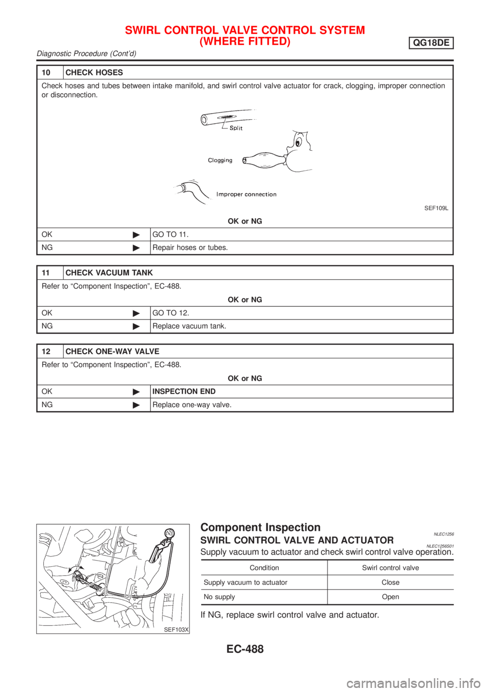
10 CHECK HOSES
Check hoses and tubes between intake manifold, and swirl control valve actuator for crack, clogging, improper connection
or disconnection.
SEF109L
OK or NG
OK©GO TO 11.
NG©Repair hoses or tubes.
11 CHECK VACUUM TANK
Refer to ÂȘComponent InspectionÂș, EC-488.
OK or NG
OK©GO TO 12.
NG©Replace vacuum tank.
12 CHECK ONE-WAY VALVE
Refer to ÂȘComponent InspectionÂș, EC-488.
OK or NG
OK©INSPECTION END
NG©Replace one-way valve.
SEF103X
Component InspectionNLEC1256SWIRL CONTROL VALVE AND ACTUATORNLEC1256S01Supply vacuum to actuator and check swirl control valve operation.
Condition Swirl control valve
Supply vacuum to actuator Close
No supply Open
If NG, replace swirl control valve and actuator.
SWIRL CONTROL VALVE CONTROL SYSTEM
(WHERE FITTED)
QG18DE
Diagnostic Procedure (Cont'd)
EC-488
Page 914 of 3051
SEF105X
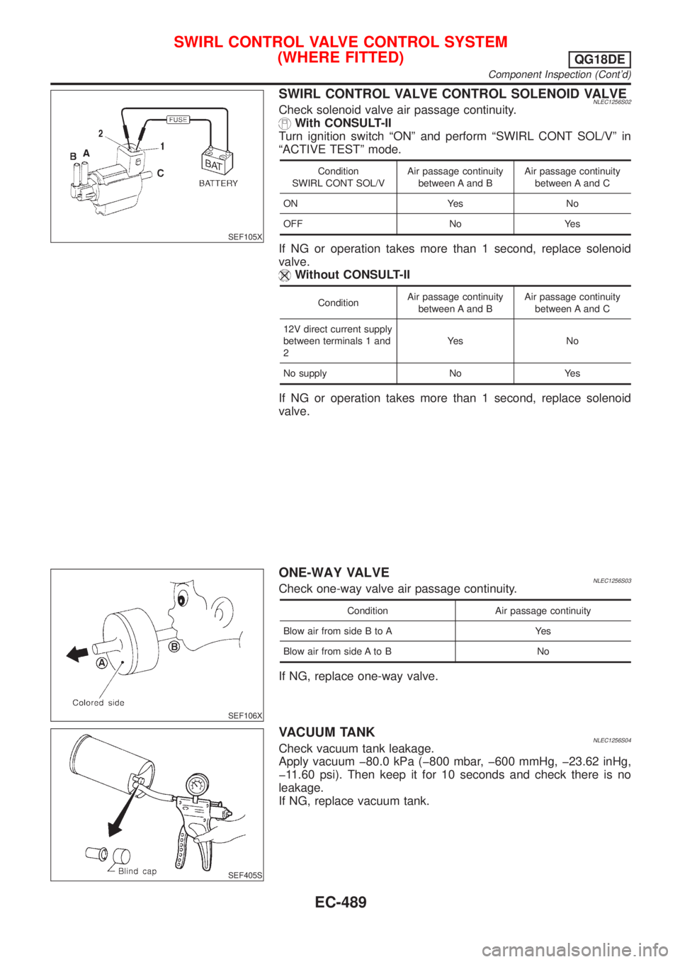
SWIRL CONTROL VALVE CONTROL SOLENOID VALVENLEC1256S02Check solenoid valve air passage continuity.
With CONSULT-II
Turn ignition switch ÂȘONÂș and perform ÂȘSWIRL CONT SOL/VÂș in
ÂȘACTIVE TESTÂș mode.
Condition
SWIRL CONT SOL/VAir passage continuity
between A and BAir passage continuity
between A and C
ON Yes No
OFF No Yes
If NG or operation takes more than 1 second, replace solenoid
valve.
Without CONSULT-II
ConditionAir passage continuity
between A and BAir passage continuity
between A and C
12V direct current supply
between terminals 1 and
2Ye s N o
No supply No Yes
If NG or operation takes more than 1 second, replace solenoid
valve.
SEF106X
ONE-WAY VALVENLEC1256S03Check one-way valve air passage continuity.
Condition Air passage continuity
Blow air from side B to A Yes
Blow air from side A to B No
If NG, replace one-way valve.
SEF405S
VACUUM TANKNLEC1256S04Check vacuum tank leakage.
Apply vacuum ĂŸ80.0 kPa (ĂŸ800 mbar, ĂŸ600 mmHg, ĂŸ23.62 inHg,
ĂŸ11.60 psi). Then keep it for 10 seconds and check there is no
leakage.
If NG, replace vacuum tank.
SWIRL CONTROL VALVE CONTROL SYSTEM
(WHERE FITTED)
QG18DE
Component Inspection (Cont'd)
EC-489
Page 915 of 3051
SEF631Z
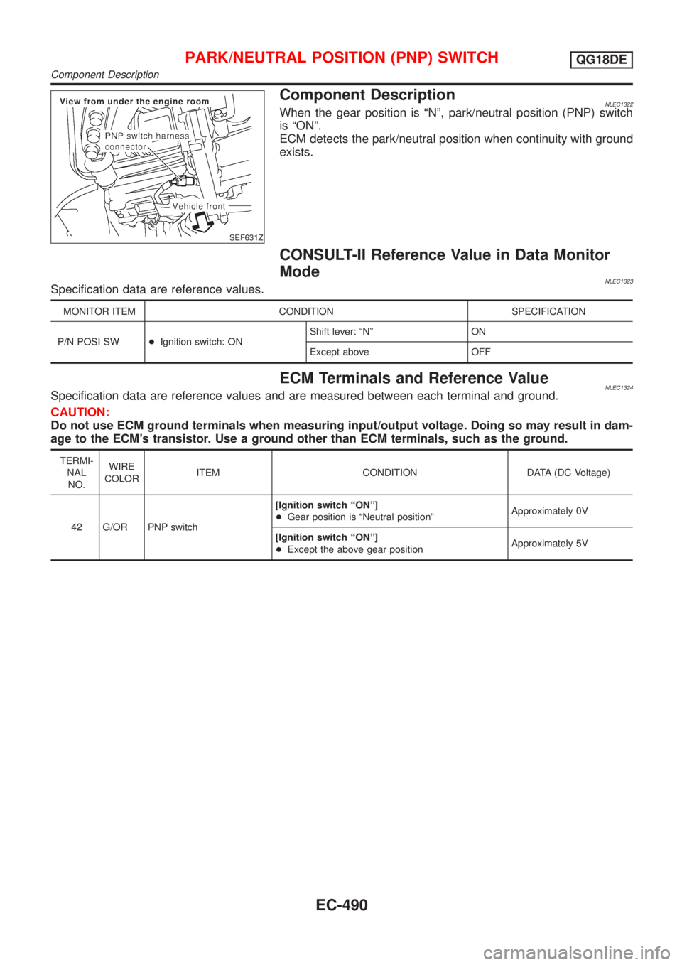
Component DescriptionNLEC1322When the gear position is ÂȘNÂș, park/neutral position (PNP) switch
is ÂȘONÂș.
ECM detects the park/neutral position when continuity with ground
exists.
CONSULT-II Reference Value in Data Monitor
Mode
NLEC1323Specification data are reference values.
MONITOR ITEM CONDITION SPECIFICATION
P/N POSI SW+Ignition switch: ONShift lever: ÂȘNÂș ON
Except above OFF
ECM Terminals and Reference ValueNLEC1324Specification data are reference values and are measured between each terminal and ground.
CAUTION:
Do not use ECM ground terminals when measuring input/output voltage. Doing so may result in dam-
age to the ECM's transistor. Use a ground other than ECM terminals, such as the ground.
TERMI-
NAL
NO.WIRE
COLORITEM CONDITION DATA (DC Voltage)
42 G/OR PNP switch[Ignition switch ÂȘONÂș]
+Gear position is ÂȘNeutral positionÂșApproximately 0V
[Ignition switch ÂȘONÂș]
+Except the above gear positionApproximately 5V
PARK/NEUTRAL POSITION (PNP) SWITCHQG18DE
Component Description
EC-490
Page 916 of 3051
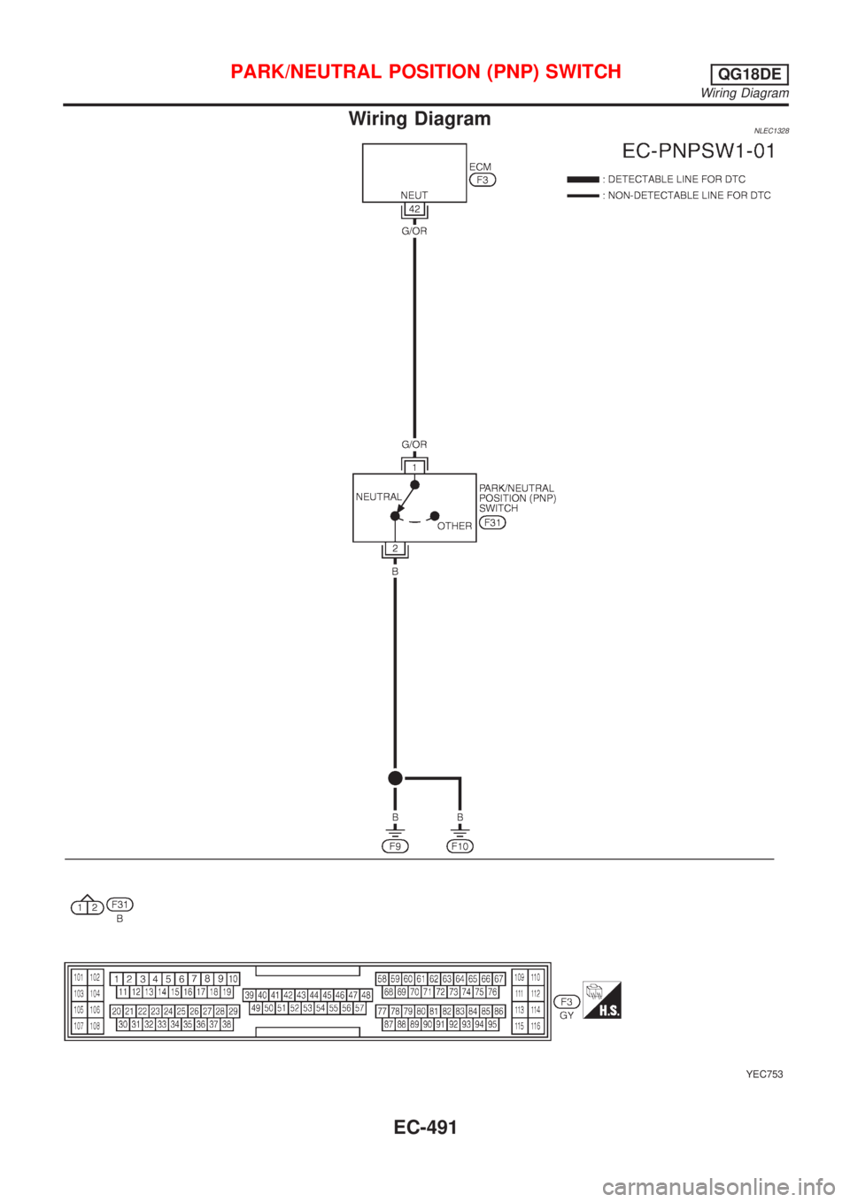
Wiring DiagramNLEC1328
YEC753
PARK/NEUTRAL POSITION (PNP) SWITCHQG18DE
Wiring Diagram
EC-491
Page 917 of 3051
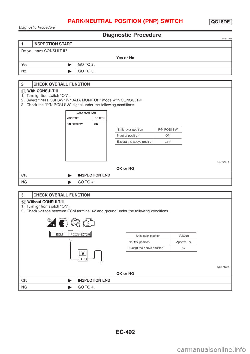
Diagnostic ProcedureNLEC1329
1 INSPECTION START
Do you have CONSULT-II?
YesorNo
Ye s©GO TO 2.
No©GO TO 3.
2 CHECK OVERALL FUNCTION
With CONSULT-II
1. Turn ignition switch ÂȘONÂș.
2. Select ÂȘP/N POSI SWÂș in ÂȘDATA MONITORÂș mode with CONSULT-II.
3. Check the ÂȘP/N POSI SWÂș signal under the following conditions.
SEF049Y
OK or NG
OK©INSPECTION END
NG©GO TO 4.
3 CHECK OVERALL FUNCTION
Without CONSULT-II
1. Turn ignition switch ÂȘONÂș.
2. Check voltage between ECM terminal 42 and ground under the following conditions.
SEF759Z
OK or NG
OK©INSPECTION END
NG©GO TO 4.
PARK/NEUTRAL POSITION (PNP) SWITCHQG18DE
Diagnostic Procedure
EC-492
Page 918 of 3051
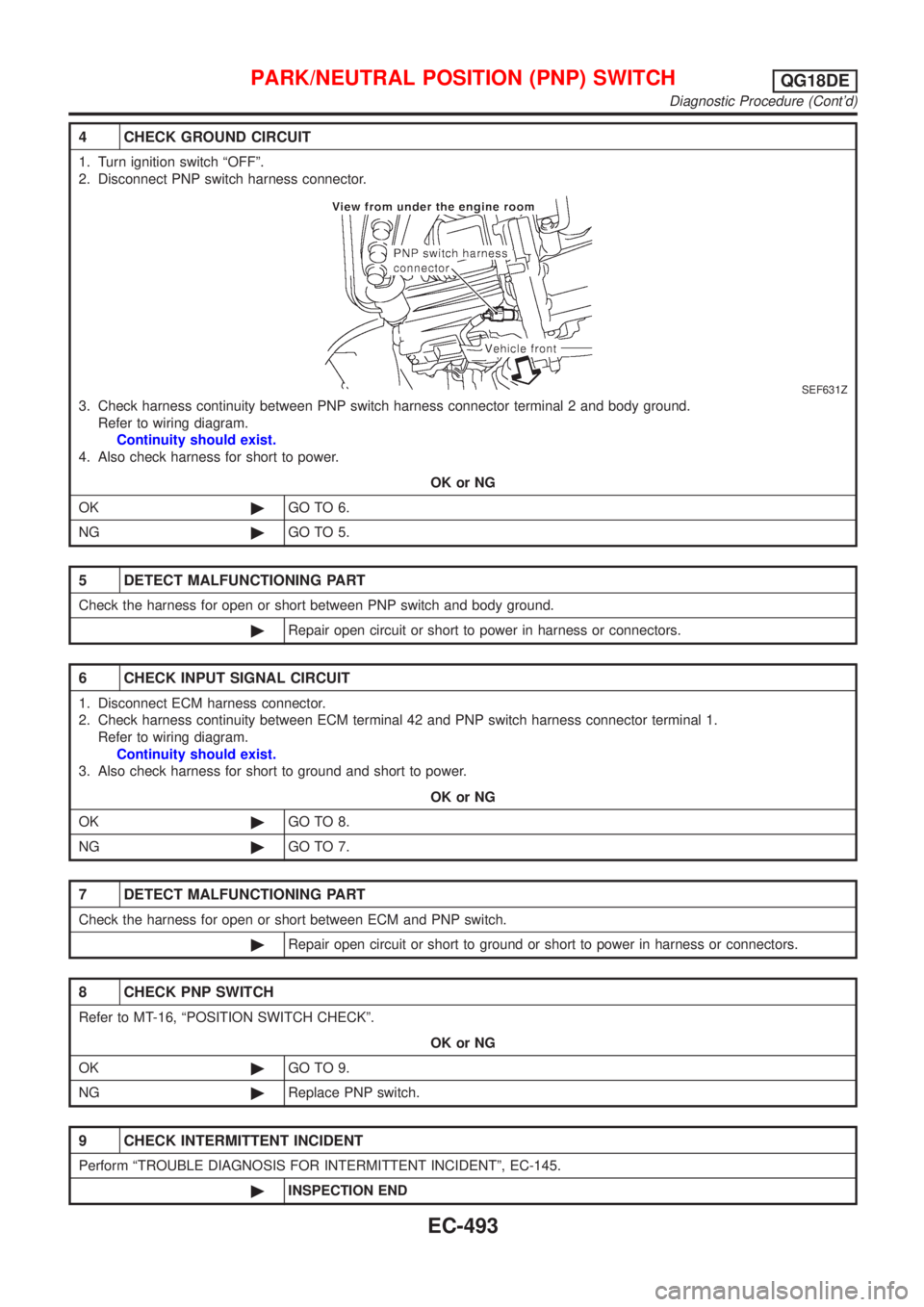
4 CHECK GROUND CIRCUIT
1. Turn ignition switch ÂȘOFFÂș.
2. Disconnect PNP switch harness connector.
SEF631Z
3. Check harness continuity between PNP switch harness connector terminal 2 and body ground.
Refer to wiring diagram.
Continuity should exist.
4. Also check harness for short to power.
OK or NG
OK©GO TO 6.
NG©GO TO 5.
5 DETECT MALFUNCTIONING PART
Check the harness for open or short between PNP switch and body ground.
©Repair open circuit or short to power in harness or connectors.
6 CHECK INPUT SIGNAL CIRCUIT
1. Disconnect ECM harness connector.
2. Check harness continuity between ECM terminal 42 and PNP switch harness connector terminal 1.
Refer to wiring diagram.
Continuity should exist.
3. Also check harness for short to ground and short to power.
OK or NG
OK©GO TO 8.
NG©GO TO 7.
7 DETECT MALFUNCTIONING PART
Check the harness for open or short between ECM and PNP switch.
©Repair open circuit or short to ground or short to power in harness or connectors.
8 CHECK PNP SWITCH
Refer to MT-16, ÂȘPOSITION SWITCH CHECKÂș.
OK or NG
OK©GO TO 9.
NG©Replace PNP switch.
9 CHECK INTERMITTENT INCIDENT
Perform ÂȘTROUBLE DIAGNOSIS FOR INTERMITTENT INCIDENTÂș, EC-145.
©INSPECTION END
PARK/NEUTRAL POSITION (PNP) SWITCHQG18DE
Diagnostic Procedure (Cont'd)
EC-493
Page 919 of 3051
SEF138X
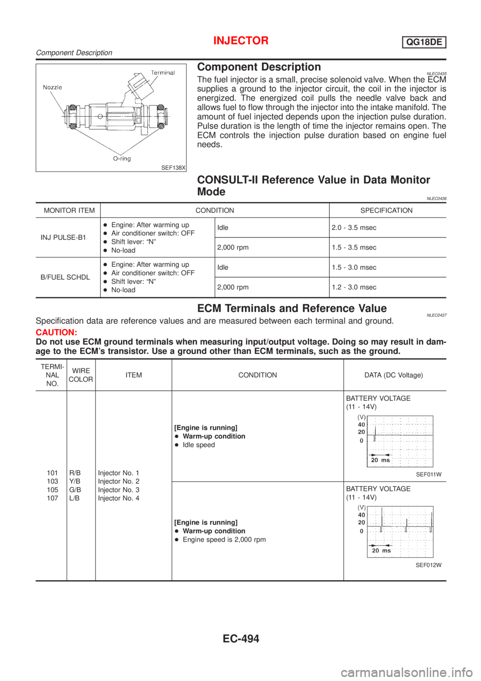
Component DescriptionNLEC0435The fuel injector is a small, precise solenoid valve. When the ECM
supplies a ground to the injector circuit, the coil in the injector is
energized. The energized coil pulls the needle valve back and
allows fuel to flow through the injector into the intake manifold. The
amount of fuel injected depends upon the injection pulse duration.
Pulse duration is the length of time the injector remains open. The
ECM controls the injection pulse duration based on engine fuel
needs.
CONSULT-II Reference Value in Data Monitor
Mode
NLEC0436
MONITOR ITEM CONDITION SPECIFICATION
INJ PULSE-B1+Engine: After warming up
+Air conditioner switch: OFF
+Shift lever: ÂȘNÂș
+No-loadIdle 2.0 - 3.5 msec
2,000 rpm 1.5 - 3.5 msec
B/FUEL SCHDL+Engine: After warming up
+Air conditioner switch: OFF
+Shift lever: ÂȘNÂș
+No-loadIdle 1.5 - 3.0 msec
2,000 rpm 1.2 - 3.0 msec
ECM Terminals and Reference ValueNLEC0437Specification data are reference values and are measured between each terminal and ground.
CAUTION:
Do not use ECM ground terminals when measuring input/output voltage. Doing so may result in dam-
age to the ECM's transistor. Use a ground other than ECM terminals, such as the ground.
TERMI-
NAL
NO.WIRE
COLORITEM CONDITION DATA (DC Voltage)
101
103
105
107R/B
Y/B
G/B
L/BInjector No. 1
Injector No. 2
Injector No. 3
Injector No. 4[Engine is running]
+Warm-up condition
+Idle speedBATTERY VOLTAGE
(11 - 14V)
SEF011W
[Engine is running]
+Warm-up condition
+Engine speed is 2,000 rpmBATTERY VOLTAGE
(11 - 14V)
SEF012W
INJECTORQG18DE
Component Description
EC-494
Page 920 of 3051
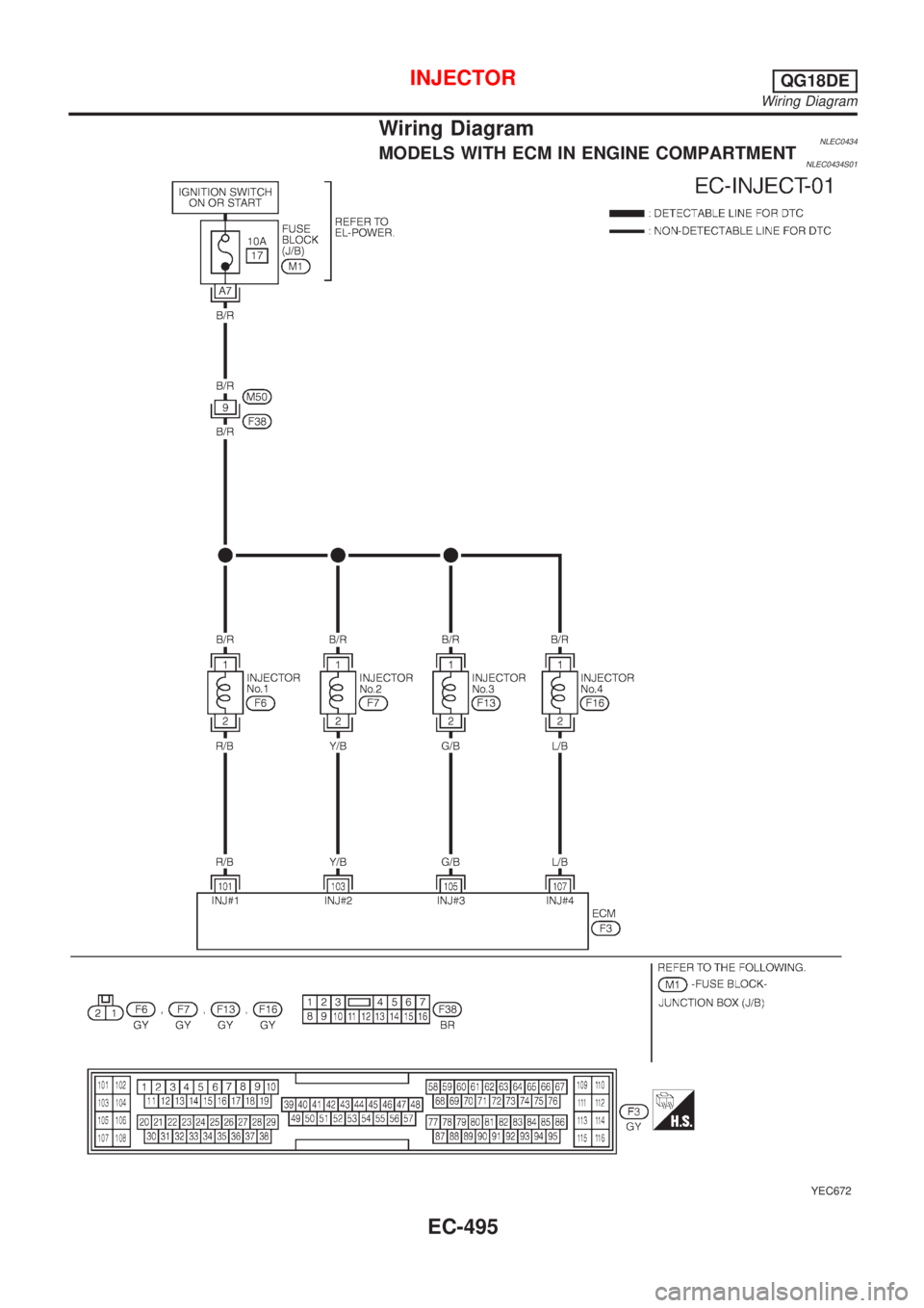
Wiring DiagramNLEC0434MODELS WITH ECM IN ENGINE COMPARTMENTNLEC0434S01
YEC672
INJECTORQG18DE
Wiring Diagram
EC-495