battery location NISSAN ALTIMA 2023 Owners Manual
[x] Cancel search | Manufacturer: NISSAN, Model Year: 2023, Model line: ALTIMA, Model: NISSAN ALTIMA 2023Pages: 644, PDF Size: 4.12 MB
Page 16 of 644
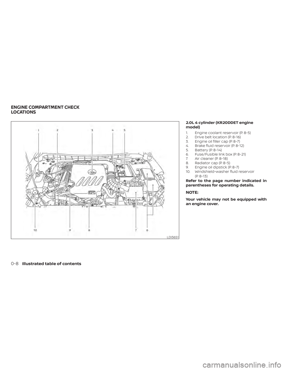
2.0L 4 cylinder (KR20DDET engine
model)
1. Engine coolant reservoir (P. 8-5)
2. Drive belt location (P. 8-16)
3. Engine oil filler cap (P. 8-7)
4. Brake fluid reservoir (P. 8-12)
5. Battery (P. 8-14)
6. Fuse/Fusible link box (P. 8-21)
7. Air cleaner (P. 8-18)
8. Radiator cap (P. 8-5)
9. Engine oil dipstick (P. 8-7)
10. Windshield-washer fluid reservoir(P. 8-13)
Refer to the page number indicated in
parentheses for operating details.
NOTE:
Your vehicle may not be equipped with
an engine cover.
LDI3651
ENGINE COMPARTMENT CHECK
LOCATIONS
0-8Illustrated table of contents
Page 17 of 644
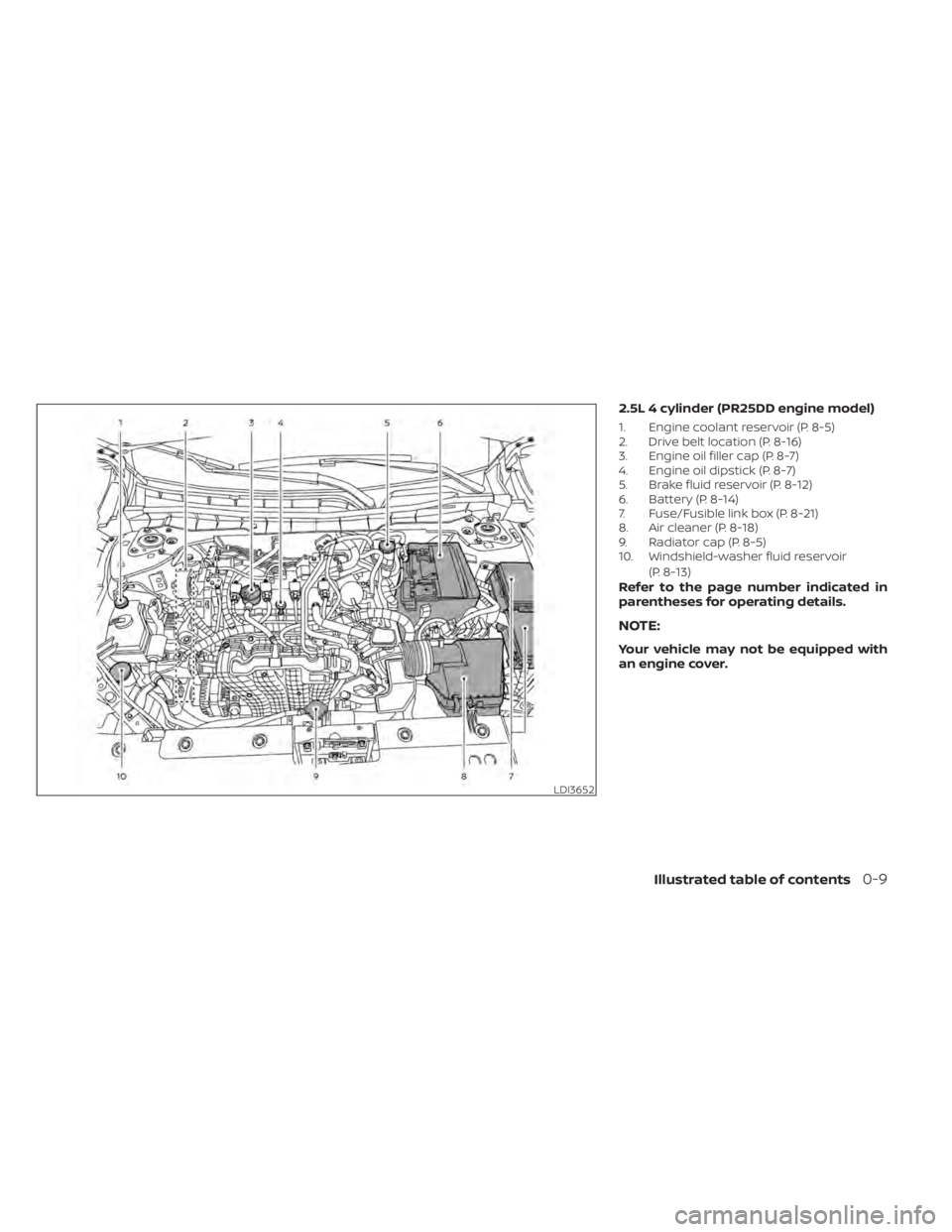
2.5L 4 cylinder (PR25DD engine model)
1. Engine coolant reservoir (P. 8-5)
2. Drive belt location (P. 8-16)
3. Engine oil filler cap (P. 8-7)
4. Engine oil dipstick (P. 8-7)
5. Brake fluid reservoir (P. 8-12)
6. Battery (P. 8-14)
7. Fuse/Fusible link box (P. 8-21)
8. Air cleaner (P. 8-18)
9. Radiator cap (P. 8-5)
10. Windshield-washer fluid reservoir(P. 8-13)
Refer to the page number indicated in
parentheses for operating details.
NOTE:
Your vehicle may not be equipped with
an engine cover.
LDI3652
Illustrated table of contents0-9
Page 185 of 644
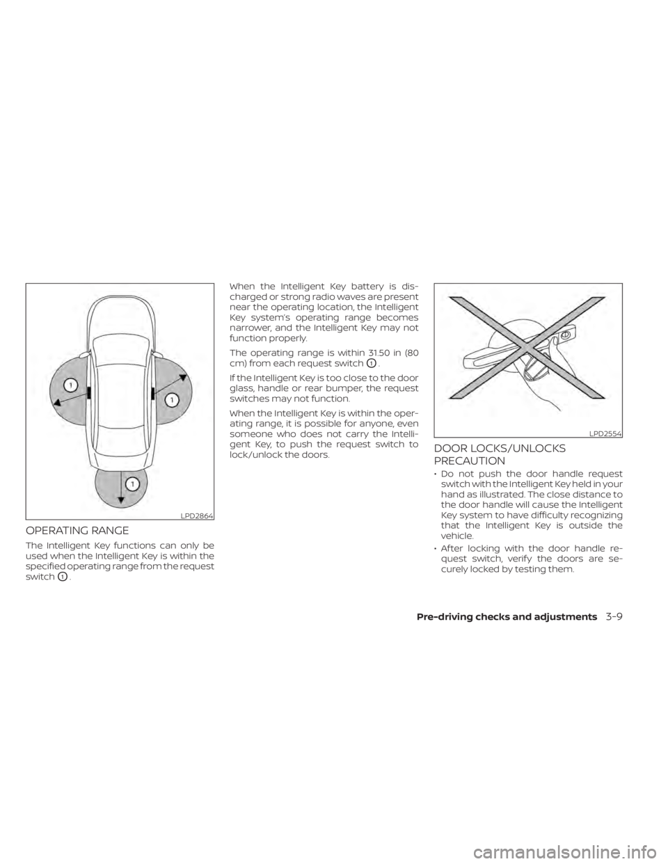
OPERATING RANGE
The Intelligent Key functions can only be
used when the Intelligent Key is within the
specified operating range from the request
switch
O1.When the Intelligent Key battery is dis-
charged or strong radio waves are present
near the operating location, the Intelligent
Key system’s operating range becomes
narrower, and the Intelligent Key may not
function properly.
The operating range is within 31.50 in (80
cm) from each request switch
O1.
If the Intelligent Key is too close to the door
glass, handle or rear bumper, the request
switches may not function.
When the Intelligent Key is within the oper-
ating range, it is possible for anyone, even
someone who does not carry the Intelli-
gent Key, to push the request switch to
lock/unlock the doors.
DOOR LOCKS/UNLOCKS
PRECAUTION
• Do not push the door handle request switch with the Intelligent Key held in your
hand as illustrated. The close distance to
the door handle will cause the Intelligent
Key system to have difficulty recognizing
that the Intelligent Key is outside the
vehicle.
• Af ter locking with the door handle re- quest switch, verif y the doors are se-
curely locked by testing them.
LPD2864
LPD2554
Pre-driving checks and adjustments3-9
Page 192 of 644
To deactivate:
Press and hold theandbut-
tons for at least 4 seconds. The hazard
indicator lights will flash three times to con-
firm that the answer back horn feature has
been deactivated.
To activate:
Press and hold the
andbut-
tons for at least 4 seconds once more.
The hazard indicator lights will flash once
and the horn will sound once to confirm
that the horn beep feature has been
reactivated.
Deactivating the horn beep feature does
not silence the horn if the alarm is
triggered.
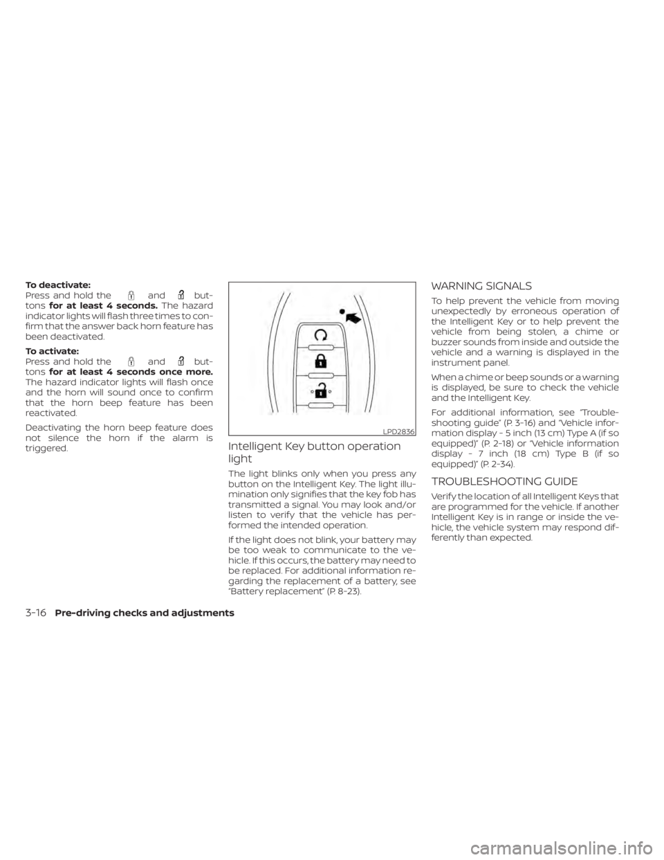
Intelligent Key button operation
light
The light blinks only when you press any
button on the Intelligent Key. The light illu-
mination only signifies that the key fob has
transmitted a signal. You may look and/or
listen to verif y that the vehicle has per-
formed the intended operation.
If the light does not blink, your battery may
be too weak to communicate to the ve-
hicle. If this occurs, the battery may need to
be replaced. For additional information re-
garding the replacement of a battery, see
“Battery replacement” (P. 8-23).
WARNING SIGNALS
To help prevent the vehicle from moving
unexpectedly by erroneous operation of
the Intelligent Key or to help prevent the
vehicle from being stolen, a chime or
buzzer sounds from inside and outside the
vehicle and a warning is displayed in the
instrument panel.
When a chime or beep sounds or a warning
is displayed, be sure to check the vehicle
and the Intelligent Key.
For additional information, see “Trouble-
shooting guide” (P. 3-16) and “Vehicle infor-
mation display - 5 inch (13 cm) Type A (if so
equipped)” (P. 2-18) or “Vehicle information
display - 7 inch (18 cm) Type B (if so
equipped)” (P. 2-34).
TROUBLESHOOTING GUIDE
Verif y the location of all Intelligent Keys that
are programmed for the vehicle. If another
Intelligent Key is in range or inside the ve-
hicle, the vehicle system may respond dif-
ferently than expected.
LPD2836
3-16Pre-driving checks and adjustments
Page 196 of 644
CAUTION
When the Intelligent Key battery is dis-
charged or other strong radio wave
sources are present near the operating
location, the Intelligent Key operating
range becomes narrower, and the Intel-
ligent Key may not function properly.
The Remote Engine Start function can only
be used when the Intelligent Key is within
the specified operating range from the
vehicle.
The Remote Engine Start operating range
is approximately 197 f t (60 m) from the
vehicle.
REMOTE STARTING THE VEHICLE
To use the Remote Engine Start feature to
start the engine perform the following:
1. Aim the Intelligent Key at the vehicle.
2. Press the
button to lock all doors.
3. Within 5 seconds press and hold the
button until the turn signal lights
flash and the tail lamps turn on. If the
vehicle is not within view press and hold
the
button for at least 2 seconds. The following events will occur when the
engine starts:
• The parking lights will turn on and remain
on as long as the engine is running.
• The doors will be locked and the climate control system may come on.
• The engine will continue to run for 10 min- utes. Repeat the steps to extend the time
for an additional 10 minutes. For addi-
tional information, see “Extending engine
run time” (P. 3-20).
Depress and hold the brake then push the
push-button ignition switch to the ON po-
sition before driving. For additional infor-
mation, see “Driving the vehicle” (P. 5-18).
EXTENDING ENGINE RUN TIME
The Remote Engine Start feature can be
extended one time by performing the
steps listed in “Remote starting the vehicle”
in this section. Run time will be calculated
as follows:
• The first 10 minute run time will start when the Remote Engine Start function is
performed. • The second 10 minutes will start immedi-
ately when the Remote Engine Start
function is performed again. For example,
if the engine has been running for 5 min-
utes, and 10 minutes are added, the en-
gine will run for a total of 15 minutes.
• Extending engine run time will count to- wards the two Remote Engine Start limit.
A maximum of two Remote Engine Starts,
or a single Remote Engine Start with an
extension, are allowed between ignition
cycles. The ignition switch must be cycled
to the ON position and then back to the
OFF position before the Remote Engine
Start procedure can be used again.
CANCELING A REMOTE ENGINE
START
To cancel a Remote Engine Start, perform
one of the following:
• Aim the Intelligent Key at the vehicle and press
until the parking lights turn off.
• Turn on the hazard warning flashers.
• Cycle the ignition switch ON and then OFF.
• The extended engine run time has expired.
• The first 10 minute timer has expired.
• The engine hood has been opened.
3-20Pre-driving checks and adjustments
Page 279 of 644
• You will not be able to use a hands-freephone under the following conditions:– Your vehicle is outside of the cellular service area.
– Your vehicle is in an area where it is difficult to receive a cellular signal; such
as in a tunnel, in an underground park-
ing garage, near a tall building or in a
mountainous area.
– Your cellular phone is locked to prevent it from being dialed.
• When the radio wave condition is not ideal or ambient sound is too loud, it may
be difficult to hear the other person's
voice during a call.
• Do not place the cellular phone in an area surrounded by metal or far away from
the in-vehicle phone module to prevent
tone quality degradation and wireless
connection disruption.
• While a cellular phone is connected through the Bluetooth® wireless connec-
tion, the battery power of the cellular
phone may discharge quicker than usual.
The Bluetooth® Hands-Free Phone Sys-
tem cannot charge cellular phones. • Some cellular phones or other devices
may cause interference or a buzzing
noise to come from the audio system
speakers. Storing the device in a different
location may reduce or eliminate the
noise.
• For additional information, refer to the cellular phone owner's manual regarding
the telephone charges, cellular phone
antenna and body, etc.
REGULATORY INFORMATION
FCC Regulatory information
– CAUTION: To maintain compliance with FCC’s RF exposure guidelines, use only
the supplied antenna. Unauthorized an-
tenna, modification, or attachments
could damage the transmitter and may
violate FCC regulations.
– Operation is subject to the following two conditions:1. 1) This device may not cause interfer- ence and
2.2) this device must accept any interfer- ence, including interference that may
cause undesired operation of the
device. IC Regulatory information
– Operation is subject to the following two
conditions: (1) this device may not cause
interference, and (2) this device must ac-
cept any interference, including interfer-
ence that may cause undesired opera-
tion of the device.
– This Class B digital apparatus meets all requirements of the Canadian
Interference-Causing Equipment
Regulations.BLUETOOTH® is a
trademark owned by
Bluetooth SIG, Inc. and
licensed to
Panasonic.
USING THE SYSTEM
The system allows hands-free operation of
the Bluetooth® Hands-Free Phone System.
If the vehicle is in motion, some commands
may not be available so full attention may
be given to vehicle operation.
Monitor, climate, audio, phone and voice recognition systems4-69
Page 310 of 644
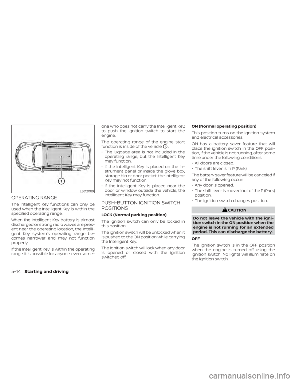
OPERATING RANGE
The Intelligent Key functions can only be
used when the Intelligent Key is within the
specified operating range.
When the Intelligent Key battery is almost
discharged or strong radio waves are pres-
ent near the operating location, the Intelli-
gent Key system’s operating range be-
comes narrower and may not function
properly.
If the Intelligent Key is within the operating
range, it is possible for anyone, even some-one who does not carry the Intelligent Key,
to push the ignition switch to start the
engine.
The operating range of the engine start
function is inside of the vehicle
O1.
• The luggage area is not included in the operating range, but the Intelligent Key
may function.
• If the Intelligent Key is placed on the in- strument panel or inside the glove box,
storage bin or door pocket, the Intelligent
Key may not function.
• If the Intelligent Key is placed near the door or window outside the vehicle, the
Intelligent Key may function.
PUSH-BUTTON IGNITION SWITCH
POSITIONS
LOCK (Normal parking position)
The ignition switch can only be locked in
this position.
The ignition switch will be unlocked when it
is pushed to the ON position while carrying
the Intelligent Key.
The ignition switch will lock when any door
is opened or closed with the ignition
switched off. ON (Normal operating position)
This position turns on the ignition system
and electrical accessories.
ON has a battery saver feature that will
place the ignition switch in the OFF posi-
tion, if the vehicle is not running, af ter some
time under the following conditions:
• All doors are closed.
• The shif t lever is in P (Park).
The battery saver feature will be canceled if
any of the following occur:
• Any door is opened.
• The shif t lever is moved out of the P (Park)
position.
• The ignition switch changes position.CAUTION
Do not leave the vehicle with the igni-
tion switch in the ON position when the
engine is not running for an extended
period. This can discharge the battery.
OFF
The ignition switch is in the OFF position
when the engine is turned off using the
ignition switch. No lights will illuminate on
the ignition switch.
LSD2089
5-14Starting and driving
Page 517 of 644
8 Do-it-yourself
Maintenance precautions.......................8-2
Engine compartment check locations ...........8-3
Engine cooling system ..........................8-5
Checking engine coolant level ................8-6
Changing engine coolant ....................8-6
Engine oil .......................................8-7
Checking engine oil level .....................8-7
Changing engine oil and oil filter ..............8-8
Continuously Variable Transmission (CVT)
fluid ............................................ 8-12
Brake fluid ...................................... 8-12
Windshield-washer fluid ........................8-13
Windshield-washer fluid reservoir ...........8-13
Battery......................................... 8-14
Jump starting ............................... 8-15
Variable voltage control system ................8-16
Drive belt ....................................... 8-16
Spark plugs .................................... 8-17
Replacing spark plugs ....................... 8-17
Air cleaner ..................................... 8-18In-cabin microfilter
.......................... 8-18
Windshield wiper blades ........................8-19
Cleaning .................................... 8-19
Replacing ................................... 8-19
Brakes ......................................... 8-20
Fuses .......................................... 8-21
Engine compartment ....................... 8-21
Passenger compartment ...................8-22
Battery replacement ........................... 8-23
NISSAN Intelligent Key® ......................8-24
Lights .......................................... 8-25
Headlights .................................. 8-25
Fog lights (if so equipped) ...................8-26
Exterior and interior lights ...................8-26
Wheels and tires ............................... 8-29
Tire pressure ................................ 8-29
Tire labeling ................................. 8-33
Types of tires ................................
8-36
Tir
e chains .................................. 8-37
Changing wheels and tires ..................8-39
Page 519 of 644
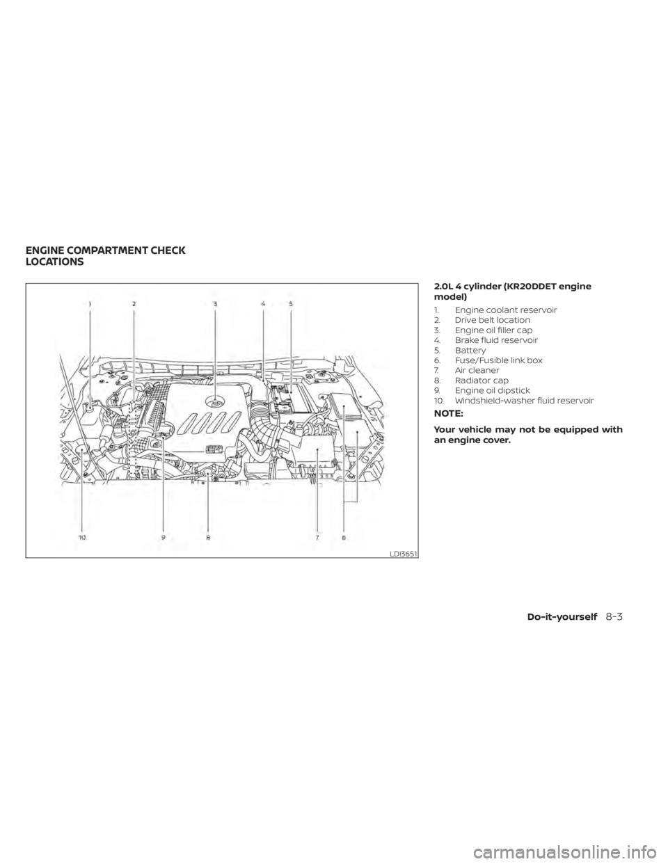
2.0L 4 cylinder (KR20DDET engine
model)
1. Engine coolant reservoir
2. Drive belt location
3. Engine oil filler cap
4. Brake fluid reservoir
5. Battery
6. Fuse/Fusible link box
7. Air cleaner
8. Radiator cap
9. Engine oil dipstick
10. Windshield-washer fluid reservoir
NOTE:
Your vehicle may not be equipped with
an engine cover.
LDI3651
ENGINE COMPARTMENT CHECK
LOCATIONS
Do-it-yourself8-3
Page 520 of 644
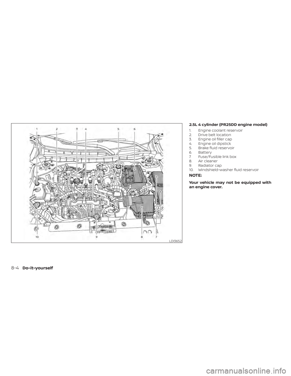
2.5L 4 cylinder (PR25DD engine model)
1. Engine coolant reservoir
2. Drive belt location
3. Engine oil filler cap
4. Engine oil dipstick
5. Brake fluid reservoir
6. Battery
7. Fuse/Fusible link box
8. Air cleaner
9. Radiator cap
10. Windshield-washer fluid reservoir
NOTE:
Your vehicle may not be equipped with
an engine cover.
LDI3652
8-4Do-it-yourself