auxiliary battery NISSAN GT-R 1998 Service Manual
[x] Cancel search | Manufacturer: NISSAN, Model Year: 1998, Model line: GT-R, Model: NISSAN GT-R 1998Pages: 230, PDF Size: 12.66 MB
Page 21 of 230

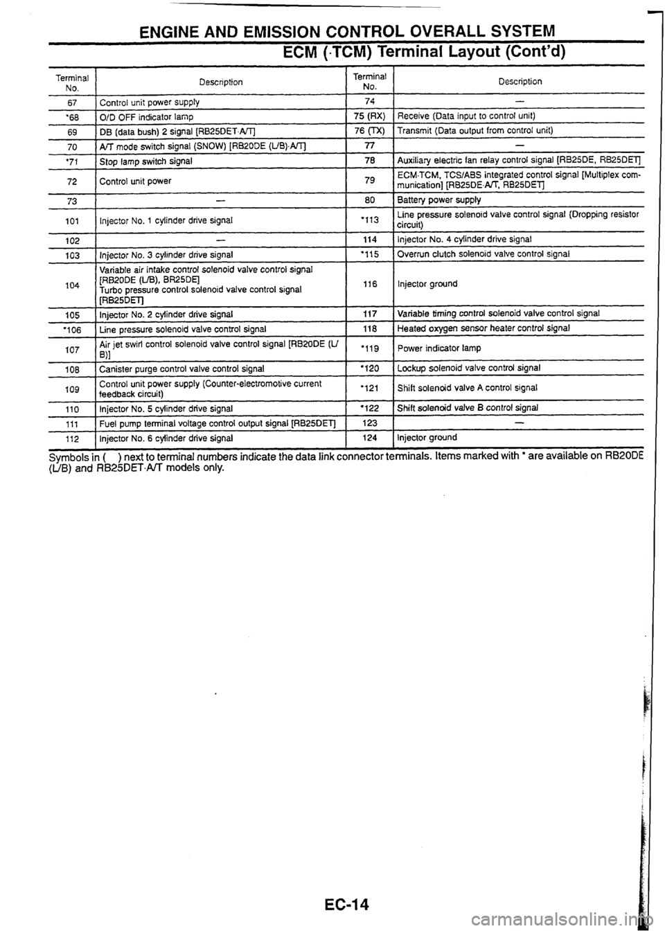
ENGINE AND EMISSION CONTROL OVERALL SYSTEM
ECM (-TCM) Terminal Layout (Cont'd)
Terminal
No.
67
'68
69 Description
70
'71
72 I
Control unit power supply
O/D OFF indicator
lamp
DB (data bush) 2 signal
[RB25DET.AIT]
73
101
104
1 [RB~ODE (LIB), BR25DEl -
Turbo oressure control solenoid valve control signal I I16 I lnjector ground
Terminal
No.
AK mode switch signal (SNOW) [RB20DE (UB).AIT]
Stop lamp switch signal
Control unit power
102
103 Description
74
75 (RX)
76
(TX)
1 I . .
-
Receive (Data input to control unit)
Transmit (Data output from control unit)
77
78
79
-
Injector No. 3 cylinder drive signal
Variable air intake control solenoid valve control
sianal
105
'106
107
-
Auxiliary electric fan relay control signal [RB25DE, RB25DElJ
ECM.TCM. TCSIABS integrated control signal [Multiplex
com-
munication] [RB25DENT. RB25DEl
Battery power supply
Line pressure solenoid valve control signal (Dropping resistor
circuit)
-
lnjector No. 1 cylinder drive signal
1 08
log
80
"I3
114
'1 15
[RB~~DET]
Injector No. 2 cylinder drive signal
Line pressure solenoid valve control signal
Air jet swirl control solenoid valve control signal
[RB20DE
(U ,\I
110 111
112 Injector No.
4 cylinder
drive signal
Overrun clutch solenoid valve control signal
"11
Canister purge control valve control signal
Control unit power supply (Counter-electromotive current
feedback
circuit) 11
7
118
.119
Symbols
in ( ) next to terminal numbers indicate the data link connector terminals. Items marked with ' are available on RB20DE (UB) and R825DET.All models only.
Injector No. 5 cylinder drive signal
Fuel pump terminal voltage control output signal
[RB25DET]
Injector No. 6 cylinder drive signal Variable
timing control solenoid valve control signal
Heated oxygen sensor heater control signal
Power indicator lamp
'120
'121 Lockup solenoid valve control signal
Shift solenoid valve
A control signal I '122
123 124 Shift solenoid valve B control signal
-
Injector ground
Page 35 of 230

TROUBLE DIAGNOSES
Symptom Matrix Chart
RELATION BETWEEN CONTROL ITEMS AND SENSORSfACTUATORS
@: High possibility to control damage 0: Low possibility to control damage
Sensors and actuators
1$1$1$ r I I
Crankshaft position sensor 1@1@1@
Ring gear crankshaft position sensor
[RB20DE (UB)] @
Mass air flow sensor
I Engine coolant temperature sensor I 0 I @ I 0 i I
Heated oxygen sensor 0
Knock sensor
Vehicle speed sensor
e? - 01 0
Throttle position sensor 000 C. $ Turbo pressure sensor (TIC) 0 0
Refrigerant pressure sensor
START
lgnition switch
@ 0
IGN 000
Air conditioner switch
Parklneutral position switch
Power steering oil pressure switch
Electrical load switch
Battery
voltage
0
injector @GO I
I power transistor I I I Ignition system I I I lgnition coil I I I I
AAC valve
Fuel DumD relav
. . I I I
2 o ECM & IGN coil relay I@l@l@ 1 I I % Auxiliary electric fan relay 3 - 2 Air conditioner relay
Canister purge control valve
0
Variable valve timing control solenoid valve
Variable air intake control solenoid valve
, (NA) Air jet swirl control solenoid valve
[RB20DE (UB)] 0
Turbo pressure control solenoid valve
(TW
FPCM (TIC)
%' Dropping resistor (TIC) 2. I I 5 Air regulator
Canister 0
Page 50 of 230

TROUBLE DIAGNOS
ECM (.TCM) lnpu
:s
3utput Signal Reference
Value (Cont'd)
.. No.
Fluctuates between approx. 0.1 to
0.4V and approx.
0.7 to
0.9V At
idle
- I I - I I -
I
I
- are measured
At approx. 2,000 rpm
:v: i .5 I .O 0.5 0
ECL 1 8645 11jllllllll ECL 1 8630
Throttle motor sensor
signal
[RB25DET'J Approx. 3.4V
I (Voltage becomes lower when TCS operates.)
Motor throttle switch
signal
[RB25DET]
Approx.
4.7V
Mass air flow sensor
signal
t
(When TCS is operating: Approx. OV)
Ignition switch ON: Approx.
0.2V
At idle: Approx.
1
.I - 1.2V Approx.
1.6 - 1.7V
Mass air flow sensor
ground Approx.
OV
I
Coolant temperature approx. 20°C: Approx. 3.5V
Coolant temperature approx.
80°C: Approx. 1.2V
Approx. 0.36V min.
(Voltage increases as the air conditioner refrigerant
pressure increases.)
Approx. 0.4
- 2V (') ': Voltage varies with measuring range (internal resis-
tame) of a circuit tester.
Battery voltage
C
+
+
+
56
-
62 1 Knock sensor signal 1
Engine coolant tem-
perature sensor signal
57
- -- -
63 1 Knock sensor signal 2
Refrigerant pressure
sensor
67 Control unit power
sup-
72
I PIY Receive (Data input to
control unit) 1
Transmit (Data output
from control unit) CONSULT
connected: Approx. 0.25V
CONSULT
not connected: Battery voltage
CONSULT connected: Approx.
9V max. CONSULT not connected: Approx. OV
C
Fan stopped: Battery voltage
Fan operating: Approx. 0.2 - 0.3V 78
NOTE: Above
Auxiliary electric fan
relay control signal
[RB25DE, RB25Dm
voltages values obtained
analog circuit
tester.